1. Read all of these instructions.
2. Save these instructions for later use.
3. All warnings on the product and in the operating instructions should be adhered to.
4. Unplug this appliance system from the wall outlet before cleaning. Do not use liquid cleaners or aerosol cleaners.
Use a damp cloth for cleaning.
5. Do not use attachments not recommended by the appliance manufacturer as they may cause hazards.
6. Do not use this appliance near water - for example, near a bathtub, washbowl, kitchen sink, or laundry tub, in a wet
basement, or near a swimming pool, etc.
7. Do not place this appliance on an unstable cart, stand, or table. The appliance may fall,
causing serious injury to a child or adult, and serious damage to the appliance may fall,
causing serious injury to a child or adult, and serious damage to the appliance.
Use only with a cart or stand recommended by the manufacturer, or sold with the appliance.
Wall or shelf mounting should follow the manufacturer's instructions, and should use a mounting
kit approved by the manufacturer.
An appliance and cart combination should be moved with care. Quick stops, excessive
force, and uneven surfaces may cause the appliance and cart combination to overturn.
8. Slots and openings in the cabinet and the back or bottom are provided for ventilation, and to
insure reliable operation of the appliance and to protect it from overheating, these openings
must not be blocked or covered. The openings should never be blocked by placing the appliance on a bed, sofa,
rug, or other similar surface. This appliance should never be placed near or over a radiator or heat register. This
appliance should not be placed in a built-in installation such as a bookcase unless proper ventilation is provided.
9. This appliance should be operated only from the type of power source indicated on the marking label. If you are
not sure of the type of power supplied to your home, consult your dealer or local power company. For appliance
designed to operate from battery power, refer to the operating instructions.
10. This appliance system is equipped with a 3-wire grounding type plug (a plug having a third (grounding) pin). This
plug will only fit into a grounding-type power outlet. This is a safety feature. If you are unable to insert the plug into
the outlet, contact your electrician to replace your obsolete outlet. Do not defeat the safety purpose of the grounding
plug.
11. For added protection for this product during a lightning storm, or when it is left unattended and unused for long
periods of time, unplug it from the wall outlet and disconnect the antenna or cable system. This will prevent
damage to the product due to lightning and power-line surges.
12. Do not allow anything to rest on the power cord. Do not locate this appliance where the cord will be abused by
persons walking on it.
13. Follow all warnings and instructions marked on the appliance.
14. Do not overload wall outlets and extension cords as this can result in fire or electric shock.
15. Never push objects of any kind into his appliance through cabinet slots as they mat touch dangerous voltage
points or short out parts that could result in a fire or electric shock. Never spill liquid of any kind on the appliance.
16. Do not attempt to service this appliance yourself as opening or removing covers may expose you to dangerous
voltage or other hazards. Refer all servicing to qualified service personnel.
17. Unplug his appliance from the wall outlet and refer servicing to qualified service personnel under following conditions:
a. When the power cord or plug is damaged or frayed.
b. If liquid has been spilled into the appliance.
c. If the appliance has been exposed to rain or water.
d. If the appliance does not operate normally by following the operating instructions. Adjust only those controls
that are covered by the operating instructions as improper adjustment of other controls may result in damage
and will often require extensive work by a qualified technician to restore the appliance to normal operation.
e. If the appliance has been dropped or the cabinet has been damaged.
f. When the appliance exhibits a distinct change in performance - this indicates a need for service.
18. When replacement parts are required, be sure the service technician has used replacement parts specified by the
manufacturer that have the same characteristics as the original part. Unauthorized substitutions may result in fire,
electric shock, or other hazards.
19. Upon completion of any service or repairs to this appliance, ask the service technician to perform routine safety
checks to determine that the appliance is in safe operating condition.
TK-C920/TK-C921
These instructions are for TK-C920U, TK-C920E and TK-C921EG.
®
IMPORTANT SAFEGUARDS
PORTABLE CART WARNING
(symbol provided by RETAC)
S3125A
For Customer Use:
Enter below the Serial No. which is located on the body.
Retain this information for future reference.
Model No.
Serial No.
Lens
DC IRIS
VIDEO IRIS
Pin No.
(does not contain EE amplifier)
(contain EE amplifier)
1
Brake
9.5V [Max. 50 mA]
2
Brake +
NC
3
Drive +
VIDEO
4
Drive
GND
1 3
4
2
The lightning flash with arrowhead symbol,
within an equi-lateral triangle, is intended to
alert the user to the presence of uninsulated
"dangerous voltage" within the product's en-
closure that may be of sufficient magnitude to
constitute a risk of electric shock to persons.
The exclamation point within an equilateral tri-
angle is intended to alert the user to the pres-
ence of important operating and maintenance
(servicing) instructions in the literature accom-
panying the appliance.
For USA and CANADA
CAUTION: TO REDUCE THE RISK OF ELECTRIC SHOCK.
DO NOT REMOVE COVER (OR BACK).
NO USER SERVICEABLE PARTS INSIDE.
REFER SERVICING TO QUALIFIED SERVICE PERSONNEL.
CAMERA type
power
TK-C920U
AC 24V ~ (class 2 only) or DC 12V
TK-C920E
AC 24V ~ (isolated power only) or DC12V
TK-C921EG
AC 220V to 240V ~ (The power cable is
2500mm in length.)
CAUTION
RISK OF ELECTRIC SHOCK
DO NOT OPEN
IRIS
VIDEO
DC
LH
COLOR VIDEO CAMERA
LEVEL
VIDEO
DC
LEVEL
(b)
(c)
F
(d)
IRIS
VIDEO
DO
LH
COLOR VIDEO CAMERA
LEVEL
(e)
AB
CD
w
q
IRIS
VIDEO
DO
LH
COLOR VIDEO CAMERA
LEVEL
4 mm
2 mm
EF
e
OUT
OFF
OFF
OFF
AUTO
LL
PHASE
ON-BLC
MANU
INT
WHT.
BAL
RESET
POWER
SEE INSTR
UCTION
MANUAL
R
B
ON-AGC
ON-AES
6mm
2mm
TK-C920
TK-C921
Information for USA
This device complies with Part 15 of the FCC Rules.
Changes or modifications not approved by JVC could void the user's authority to operate the equipment.
INFORMATION (FOR CANADA) RENSEIGNEMENT (POUR LE CANADA)
This Class [B] digital apparatus complies with Canadian ICES-003.
Cet appareil numérique de la classe [B] est conforme à la norme NMB-003 du Canada.
COLOR VIDEO CAMERA
Instructions
Thank you for purchasing the JVC color video camera.
To obtain the best results from your new camera, read these instructions carefully before use;
retain the manual for future reference.
WARNING:
TO PREVENT FIRE OR SHOCK HAZARD, DO NOT EXPOSE THIS UNIT TO RAIN OR MOIS-
TURE.
Due to design modification, data given in this instruction book are subject to possible change
without prior notice.
PRECAUTIONS
· Picture may not appear correctly if white-spot correction is performed incorrectly. Follow the
steps listed in the instructions. (Reference: White-spot correction
I) Do not perform this op-
eration when there are no white spots.
· If an AGC switch is turned on, the sensitivity increases automatically in dark places. It is not a
failure when the image looks grainy.
· If a zoom lens is used, check the back focus before mounting the camera. This also applies to
lens ALC and LEVEL. (See the instructions on lenses for details.)
· If a high-intensity object (such as a lamp) is shot, the image on the screen may have vertical
lines (smear) or blur (blooming) at its periphery (especially in AES mode). This is a characteristic
of the CCD, and is not a defect.
· If an EE lens is used, set the automatic electronic shutter switch (AES) to OFF. If set to ON,
flickering may occur. If a manual iris lens is used, set the AES to ON.
· When used in hot places, vertical lines may appear on the screen of this camera. This is a
characteristic of the CCD and not a failure of the camera.
· The automatic tracking system may not function properly when shooting with non-standard
lighting or lighting with a color temperature which exceeds the capability of the camera. In such
a case, set to the "MANU" position.
· If the camera subject is a single solid color (other than white), the auto white circuit will normally
attempt to change this color to white. In the case of this camera, if it cannot make a correct prediction,
the previous white balance setting will be maintained until the subject colors become more varied.
· Noise may appear in the picture and/or the colors may be incorrect if the camera is used near a radio
or television transmitting antenna, in places where strong electromagnetic waves are generated by
transformers, motors, etc., or near devices emitting radio waves, such as transceivers or cellular phones.
·To save energy, be sure to turn off the system when not in use.
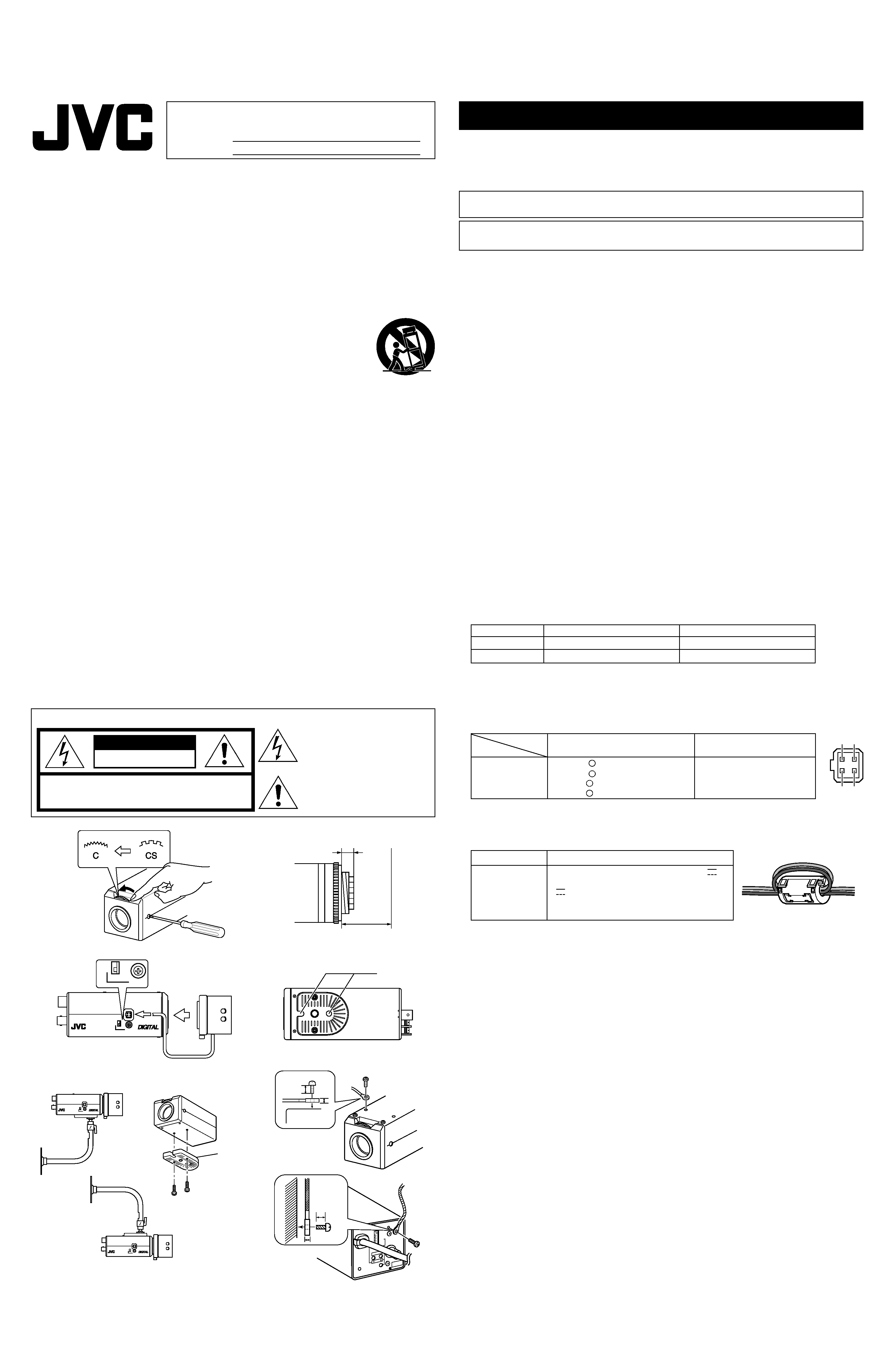
MOUNTING A LENS
1. Before mounting a lens, check whether it is a C-mount or CS-mount lens.
If a C-Mount lens is used, loosen the back-focus locking screw (M 2.6) using a Phillips
head screwdriver, turn the back-focus adjusting ring with your fingers or the screw-
driver and change the mounting method.
2. Dimension (b) of the lens shown in the illustration must be as shown in the table
below. If (b) exceeds the value in the table, it may damage the inside of the camera
or correct mounting may be impossible; never use such lenses. Do not attach the C-
mount lens when using a CS-mount.
The F mark indicates a focal point.
3. Mount the lens on the camera by turning the lens clockwise. Adjust its position.
4. When using an auto-iris lens with an EE amplifier, turn the switch to the "VIDEO"
side. When no EE amplifier is equipped, turn the switch to the "DC" side.
5. If the lens has an auto-iris mechanism,
Connect the lens cable after checking the pin arrangement.
*4 pin plug, service part number: SCV2859-001
For details, please consult your JVC dealer.
CONNECTION
1. When the camera is powered, the POWER LED lights up.
U/E only: Installing the ferrite core
To retain electromagnetic compatibility, use the ferrite core provided when connecting to the power source.
* Install the ferrite cores within 50 mm of the camera-side connectors.
·Never connect the DC 12V and AC 24V power inputs simultaneously.
· Be sure to observe the correct +, polarity when connecting a DC 12V power input.
EG only: When you use this camera, the socket - outlet must be installed near the equipment to
make disconnect on easily.
2. Connect to a video monitor, etc. (75 )
3. To install the camera onto a tripod, fixing unit, or pan/tilt unit, use the fall-preventive
socket (d) shown in the illustration.
Special precautions must be taken for mounting the camera on a wall or a ceiling.
We are not liable for any damage caused by improper installation.
4. Installation of camera
· Mounting from the bottom
This camera is originally designed to be mounted from the bottom, as shown
q.
The hole is standard photographic pan-head screw size (1/4-20 UNC). Example
the Fixing unit or Pan/Tilt unit.
· Mounting from the top
Remove the CAMERA MOUNTING BRACKET (e) from the bottom of the camera by removing
two fixing screws as shown
w. Attach the CAMERA MOUNTING BRACKET (e) to the top,
then mount the camera on the Fixing Unit as shown
e. Make sure that two original screws are
used when mounting the CAMERA MOUNTING BRACKET (e); longer type screws (over 5mm)
may damage inner components.
(This camera is used indoor and under similar conditions.)
Fall Prevention
·Exercise maximum caution when installing the unit to the wall or ceiling. You should
not engage in the installation work yourself. Ask a professional to do the job, since
the fall of the unit can result in injuries and accidents.
· When installing the unit on a fixer, turn table, etc., make sure to install it firmly using
a rotation-preventing hole provided to prevent fall.
· As a failsafe against falling, attach the unit by chain, wire cable or other safety restraint to an appropri-
ate anchor point. Attach the fall prevention wire using the black screw on the upper surface of the
camera as shown in figure F. When changing the side at which CAMERA MOUNTING BRACKET is
installed, be sure to change the attachment side of the fall prevention wire also to the appropriate side.
· Specified screw (TK-C920: M2.6 × 4 mm, TK-C921: M3 × 6 mm)
Never use any screw longer than the specified length as the inside can be damaged.
Lens
Flange back (c)
Dimension (b)
C mount lens
17.526mm
10mm or less
CS mount lens
12.5mm
5.5mm or less
A
B
C
D
E
F
Monitor screen
ALC turning direction
Part (high-intensity part) of the screen halates.
Clockwise (Toward Pk)
Other part of screen (except high-intensity part) darkens.
Counterclockwise (Toward Av)
Monitor screen
LEVEL turning direction
Too bright
Counterclockwise (Toward L)
Too dark
Clockwise (Toward H)
©2004 VICTOR COMPANY OF JAPAN, LIMITED
® is a Registered Trademark owned by VICTOR COMPANY OF JAPAN, LTD.
® is a Registrated Trademark in Japan,the U.S.A., the U.K. and many other countries.
®
VICTOR COMPANY OF JAPAN, LIMITED
BF LOCK
IRIS
VIDEO
DC
LH
LEVEL
ALC
LEVEL
Av
Pk
L
H
ALC
LEVEL
1,5
4
COLOR VIDEO CAMERA
BF LOCK
126
115
30
1/4-20 UNC
U1-32
50
50
58
32.5
51
G
J
K
HI
COLOR VIDEO CAMERA
DIGITAL
BF LOCK
126
115
65
U1-32
42
30
35
55
62.5
1/4-20UNC
RB
DC12V
AC24V
2
1
VIDEO OUT
SEE INSTRUCTION
MANUAL
POWER RESET
OFF
OFF
OFF
AUTO
LL
PHASE
WHT.
BAL
INT
MAMU
ON-BLC
ON-AES
ON-AGC
CLASS 2 ONLY(U TYPE)
ISOLATED POWER ONLY
(E TYPE)
1
2
4
3
5
6
7
8
OFF
ON-AGC
ON-AES
ON-BLC
MANU
INT
WHT.
BAL
OFF
OFF
AUTO
LL
PHASE
RESET
RB
POWER
VIDEO OUT
SEE INSTRUCTION
MANUAL
1
4
3
5
6
7
8
Printed in Thailand
LWT0124-001B-H
TK-C920
TK-C921
TK-C920
TK-C921
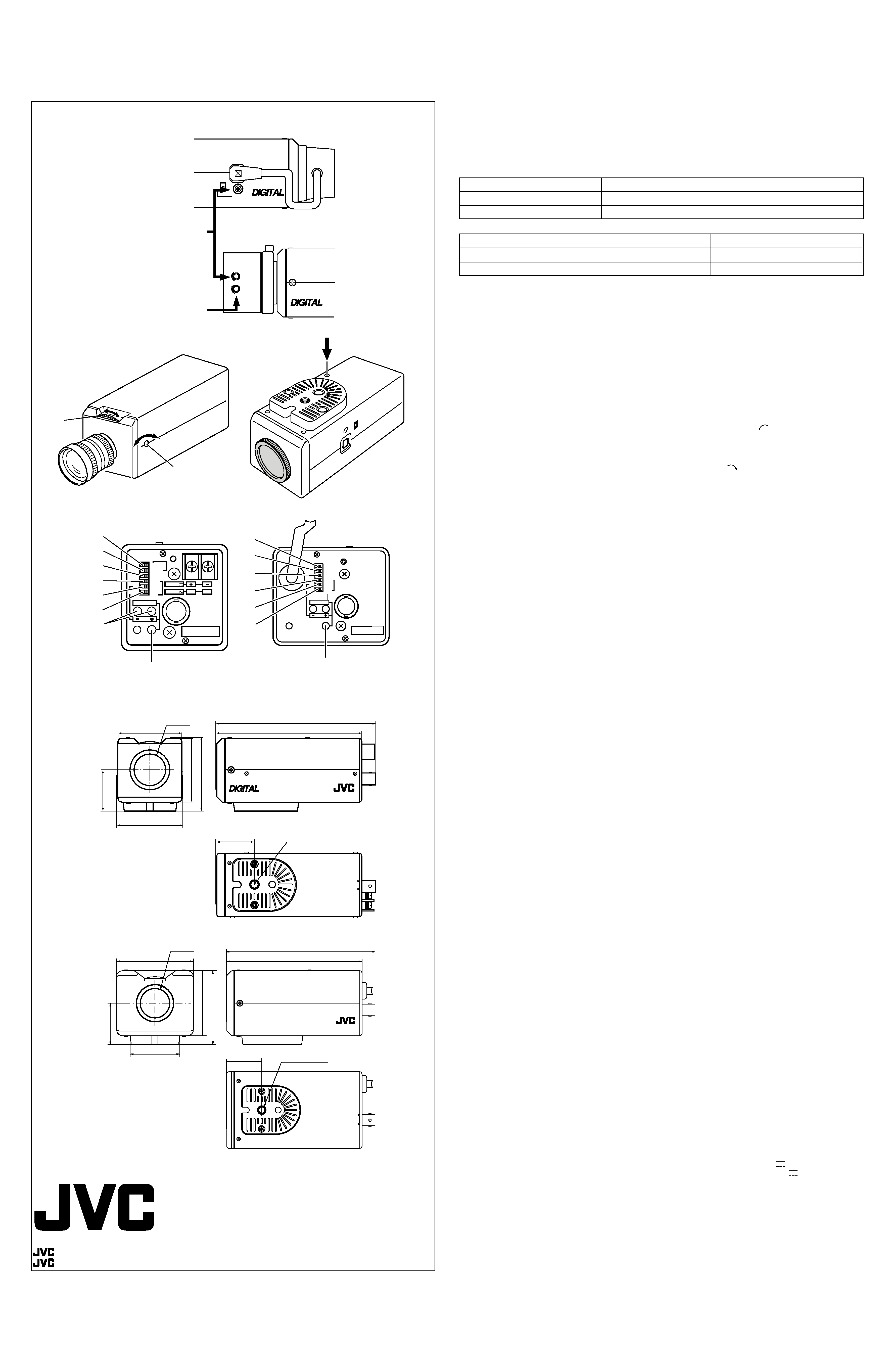
LENS ADJUSTMENT
Video adjust
Connect the camera according to the connection method, turn it on, display an image on the
monitor, and check the image. The camera has been factory-adjusted to the best position, but it
may need to be adjusted according to the object conditions or combination of lenses. If the image
is unnatural, adjust it as follows:
· LEVEL adjustment
· ALC adjustment
* If the sensitivity adjustment LEVEL is turned excessively to L, the sensitivity increases because
of the AGC function of the camera, and the image looks grainy.
* If the video iris lens is set to too low a level, malfunction such as the hunting phenomenon, in
which the iris opens or closes unintentionally, may occur.
In such a case, first set LEVEL potentiometer on the lens to the H (iris open) position then adjust
it to the optimum level.
Back focus adjustment
The back focus has been factory-adjusted to the best point for CS-mount lens, but it
may need to be re-adjusted if the mount is changed to the C-mount or if a different lens
is used. If required, adjust it as follows:
If the focus can not be adjusted correctly by rotating the lens focus ring, adjust the back focus as
follows.
1. Loosen the back focus locking screw by turning it counterclockwise (
) with a screwdriver.
2. Shoot a pattern closely.
3. Turn the lens focus ring to
.
4. Turn the back focus adjustment ring to focus at the best point.
5. Tighten the back focus locking screw by turning it clockwise (
).
* When using a zoom lens, adjust the focus for telephoto wide-angle and maximum wide-angle.
SETTING SWITCH
White-spot correction
As a general characteristic unique to CCD, white spots may appear on the screen. Take the follow-
ing steps in order to reduce the number of white spots.
1. Attach the lens cap, switch on the camera power supply and wait for 30 minutes.
2. Remove the sticker and press and hold the switch for more than 2 seconds using a thin rod.
* Do not use a metal rod.
* The white-spot correction feature of this unit does not guarantee the correction of all white spots.
Line Lock (U type : 60Hz power region only E/EG type : 50Hz power region only)
To set the camera in LL mode for synchronization with the power supply frequency, take
the following steps:
1. Turn switch
r to "LL";
2. Turn switch
e to "PHASE";
3. Press the + or button
w to make the phase variable.
Adjust with the button
w so that the vertical phase of the camera matches the vertical phase of
another camera (or system) with a multi-channel oscilloscope.
For initial setting, press RESET button
q.
White Balance
White balance can be adjusted within the scope of 2300K to 10000K color temperature. When
switch
t is at "AUTO", the white balance is adjusted automatically.
* When Hunting Auto Tracking White Balance symptoms occur when using an Auto iris lens with
switch positions of AGC is on, AES is on, Int-lock with AC24V Power source, turn switch
r to
"LL".
* When Hunting Auto Tracking White Balance symptoms occur when using a Manual iris lens with
switch positions of AGC is on, AES is on, Int-lock with DC12V Power source, please adjust or
close iris ring on the lens.
For manual adjustment, take the following steps:
1. Turn switch
t to "MANUAL";
2. Turn switch
e to "WHT.BAL";
3. Pressing "R" button
w increases redness while pressing "B" increases blueness. For initial
setting, press RESET button
q.
There are cases sometimes when the white balance cannot be adjusted manually for artifical
lights such as fluorescent lights, etc.
BLC (Back Light Compensation)
The switch
y improves an image that is darkened because of backlighting.
Set this switch to ON for backlight subjects.
AES (Automatic Electronic Shutter)
Turning this switch
u "ON" when a lens with a manual iris diaphragm is used enables the auto-
matic adjustment of image brightness. In this case the shutter speed changes according to the
brightness of the subject.
* Hunting may occur at a certain object brightness due to the mechanism of the AES circuit, but this
is not a fault.
AGC (Automatic Gain Control)
The switch
i automatically increases the camera's sensitivity when the level of ambient light
drops.
ON: AGC is activated.
OFF: AGC is not activated.
SPECIFICATIONS
Image pickup device
: 1/3-inch interline-transfer CCD
Number of effective pixels
: TK-C920U
: 768 (H) × 494 (V)
TK-C920E/TK-C921EG : 752 (H) × 582 (V)
Synchronization method
: Internal
Line lock (U type 60 Hz, E/EG type 50 Hz regions only)
Scanning frequency
:U type
: (H) 15.734 kHz (V) 59.94 Hz
E/EG type : (H) 15.625 kHz (V) 50 Hz
Resolution
: 535 TV line (H) Typ.
Video output
: Composite video signal 1 V (p-p), 75 , unbalanced
Video S/N ratio
: 50 dB (AGC OFF)
Minimum required illumination : 0.7 lx (F1.2, AGC ON, 25%)
Lens mount
: C/CS mount
Power supply
: TK-C920U
: AC24 V
~ 60Hz DC12 V
4.7 W
and power consumption
TK-C920E
: AC24 V
~ 50/60Hz DC12 V
380 mA
TK-C921EG : AC220 V-240 V
~ 50/60Hz, 57 mA
Ambient temperature
: 10°C to 50°C (operation)
0°C to 40°C (recommended)
Mass
: TK-C920: 370 g
TK-C921: 710 g
DIMENSIONS (Unit: mm)
(Design and specifications are subject to change without notice.)
G
H
I
J
K