TK-C655
DOME TYPE CAMERA
INSTRUCTIONS
LWT0050
2
IMPORTANT SAFEGUARDS
1. Read all of these instructions.
2. Save these instructions for later use.
3. All warnings on the product and in the operating instructions should be adhered to.
4. Unplug this appliance system from the wall outlet before cleaning. Do not use liquid cleaners or aerosol cleaners. Use
a damp cloth for cleaning.
5. Do not use attachments not recommended by the appliance manufacturer as they may cause hazards.
6. Do not use this appliance near water for example, near a bathtub, washbowl, kitchen sink, or laundry tub, in a wet
basement, or near a swimming pool, etc.
7. Do not place this appliance on an unstable cart, stand, or table. The appliance may fall,
causing serious injury to a child or adult, and serious damage to the appliance.
Use only with a cart or stand recommended by the manufacturer, or sold with the appliance.
Wall or shelf mounting should follow the manufacturer's instructions, and should use a
mounting kit approved by the manufacturer.
An appliance and cart combination should be moved with care. Quick stops, excessive
force, and uneven surfaces may cause the appliance and cart combination to overturn.
8. Slots and openings in the cabinet and the back or bottom are provided for ventilation, and to
insure reliable operation of the appliance and to protect it from overheating, these openings
must not be blocked or covered. The openings should never be blocked by placing the appliance on a bed, sofa, rug,
or other similar surface. This appliance should never be placed near or over a radiator or heat register. This appliance
should not be placed in a built-in installation such as a bookcase unless proper ventilation is provided.
9. This appliance should be operated only from the type of power source indicated on the marking label. If you are not
sure of the type of power supplied to your home, consult your dealer or local power company. For appliance designed
to operate from battery power, refer to the operating instructions.
10. This appliance system is equipped with a 3-wire grounding type plug (a plug having a third (grounding) pin). This plug
will only fit into a grounding-type power outlet. This is a safety feature. If you are unable to insert the plug into the
outlet, contact your electrician to replace your obsolete outlet. Do not defeat the safety purpose of the grounding plug.
11. For added protection for this product during a lightning storm, or when it is left unattended and unused for long
periods of time, unplug it form the wall outlet and disconnect the antenna or cable system. This will prevent damage to
the product due to lightning and power-line surges.
12. Do not allow anything to rest on the power cord. Do not locate this appliance where the cord will be abused by
persons walking on it.
13. Follow all warnings and instructions marked on the appliance.
14. Do not overload wall outlets and extension cords as this can result in fire or electric shock.
15. Never push objects of any kind into this appliance through cabinet slots as they may touch dangerous voltage points
or short out parts that could result in a fire or electric shock. Never spill liquid of any kind on the appliance.
16. Do not attempt to service this appliance yourself as opening or removing covers may expose you to dangerous
voltage or other hazards. Refer all servicing to qualified service personnel.
17. Unplug this appliance from the wall outlet and refer servicing to qualified service personnel under the following condi-
tions:
a. When the power cord or plug is damaged or frayed.
b. If liquid has been spilled into the appliance.
c. If the appliance has been exposed to rain or water.
d. If the appliance does not operate normally by following the operating instructions. Adjust only those controls that
are covered by the operating instructions as improper adjustment of other controls may result in damage and will
often require extensive work by a qualified technician to restore the appliance to normal operation.
e. If the appliance has been dropped or the cabinet has been damaged.
f.
When the appliance exhibits a distinct change in performance this indicates a need for service.
18. When replacement parts are required, be sure the service technician has used replacement parts specified by the
manufacturer that have the same characteristics as the original part. Unauthorized substitutions may result in fire,
electric shock, or other hazards.
19. Upon completion of any service or repairs to this appliance, ask the service technician to perform routine safety
checks to determine that the appliance is in safe operating condition.
PORTABLE CART WARNING
(symbol provided by RETAC)
S3126A

3
WARNING:
TO REDUCE THE RISK OF FIRE OR
ELECTRIC SHOCK, DO NOT EXPOSE THIS
APPLIANCE TO RAIN OR MOISTURE.
AVERTISSEMENT:
POUR EVITER LES RISQUES D'INCENDIE OU
D'ELECTROCUTION, NE PAS EXPOSER
L'APPAREIL A L'HUMIDITE OU A LA PLUIE.
Contents
Introduction
Features ............................................................................................................................................................................. 4
Provided Accessories ......................................................................................................................................................... 4
Safety Precautions ............................................................................................................................................................. 5
Precautions for Correct Operation ...................................................................................................................................... 5
Controls, Connectors and Indicators .................................................................................................................................. 6
Connections & Installation
A Multi-Drop Communication System ................................................................................................................................ 8
Point-to-Point Communication System ............................................................................................................................. 10
Switch Settings ................................................................................................................................................................. 12
Cable Connections ........................................................................................................................................................... 14
Attaching the Ceiling Mount ............................................................................................................................................. 16
Attaching the Camera ....................................................................................................................................................... 16
Setting Up the Camera using an RM-P2580
Setup Procedure .............................................................................................................................................................. 18
Menu Screen Flow ............................................................................................................................................................ 19
CAMERA FUNCTION Screen .......................................................................................................................................... 20
CAMERA TITLE/ALARM Screen ...................................................................................................................................... 21
CAMERA VIDEO ADJUSTMENT Screen ........................................................................................................................ 22
CAMERA ALC/ExDR Screen ........................................................................................................................................... 22
AUTO PAN/PATROL/TRACE Screen ................................................................................................................................ 24
POSITION FUNCTION SET Screen ................................................................................................................................ 24
FACTORY SETTINGS Screen .......................................................................................................................................... 25
PRIVATE MASK Setup ..................................................................................................................................................... 26
CAMERA TITLE Setup ..................................................................................................................................................... 27
AREA TITLE Setup ........................................................................................................................................................... 28
ALARM TITLE Setup ........................................................................................................................................................ 29
AUTO PAN Setup ............................................................................................................................................................. 30
AUTO PATROL Setup ....................................................................................................................................................... 31
AUTO TRACE Setup ........................................................................................................................................................ 32
POSITION TITLE Setup ................................................................................................................................................... 33
Other
Attaching a Flush Mounted Ceiling Bracket (Optional WB-S575) ..................................................................................... 34
Removing a Flush Mounted Ceiling Bracket (Optional WB-S575) ................................................................................... 36
Troubleshooting ................................................................................................................................................................ 37
Specifications ................................................................................................................................................................... 38
Thank you for purchasing this product.
(These instructions are for TK-C655E)
Before beginning to operate this unit, please read the instruction manual carefully in order to make sure that the best possible
performance is obtained.
4
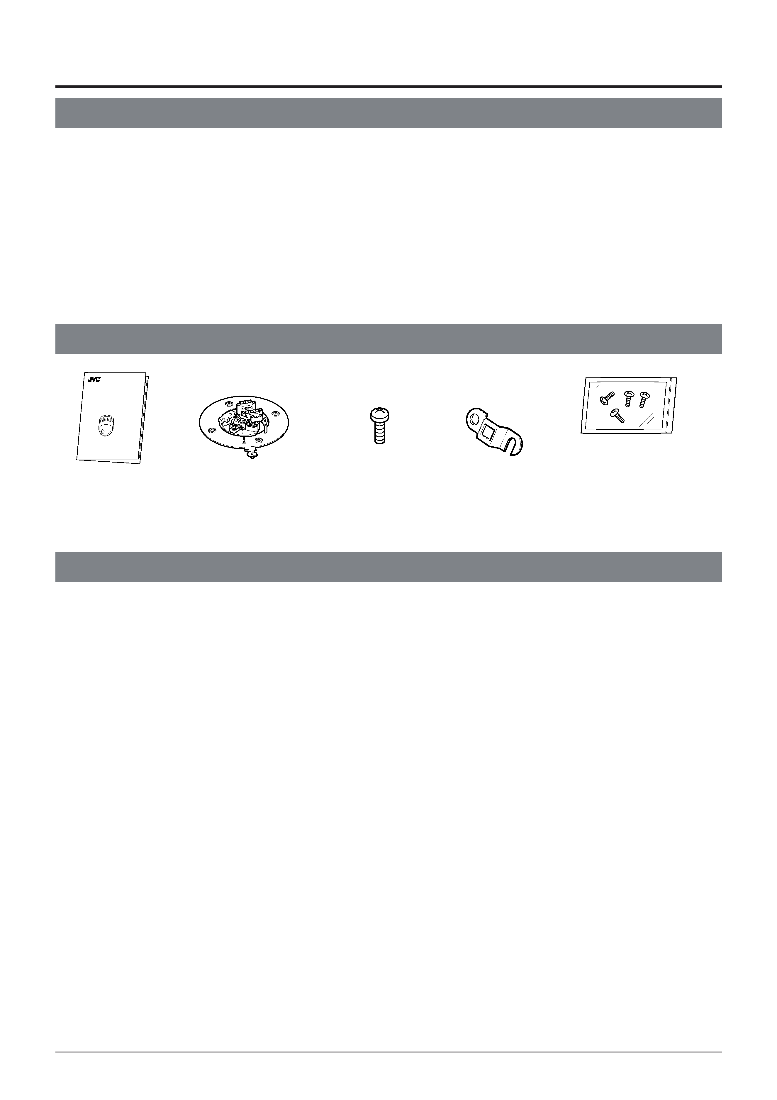
Provided Accessories
Features
DSP with a wide dynamic range
Even objects differing greatly in brightness can be monitored clearly.
Private masking facility
When the camera target area needs to be hidden, the camera can be set accordingly to mask it.
Optical zoom lens
Detailed surveillance can be performed with the approx. 25 times optical zoom lens.
High-speed pan/tilt table
The high-speed rotating table with a horizontal panning speed of 300°/sec. and a vertical tilting speed of 180°/sec. makes it
possible to get to a preset position very quickly.
Introduction
WARNING
· Install the unit on a strong and stable surface.
This unit has been designed to rotate at high speed. Due to its weight (about 2.4 kg) and to the vibrations whit it may be subjected,
the camera must be mounted to sturdy and stable material. If the ceiling material lacks strength, for example it is made of a decorative
laminated material or plasterboard, then the mount should be reinforced using materials such as veneered plywood. If such reinforce-
ment is inadequate images may be unstable due to vibration or, in the worst case, the camera may fall and cause a serious accident
should there be anyone below it.
·For installation, use the provided Ceiling Mount and the optional flush mounted ceiling bracket, which is sold separately.
When installing this device the provided Ceiling Mount and the optional flush mounted ceiling bracket, which is sold separately
should be used. Also be sure to connect the drop prevention wire and tighten all screws and nuts firmly.
·Power the unit with the rated power voltage.
The power rating for this unit is 24 V AC, 50 Hz/60 Hz. If a power above this rating is supplied, a malfunction will occur or, in the
worst case, smoke or fire may be produced.
· This unit offers a certain degree of protection against any damage either to itself or to its connection cable that might result from
indirect lightning strikes, but it is not capable of preventing all damage caused by lightning strikes, for example it is not protected
against a direct strike. If lightning damage can be expected in the place where the unit is installed, be sure to take countermeas-
ures by adding an arrester to the connection cable, etc.
CAUTION
· Installation of this unit requires special skills. Please be sure to consult JVC authorized dealer about installation procedures.
If the mounting screws or nuts are not tightened sufficiently, the camera may fall from its installation location. Be sure to tighten the
mounting nuts firmly to prevent this happening.
· Inspect the unit periodically.
Check periodically for any deterioration of the mount sections or loosening of screws due to vibration and ensure that there is no
likelihood of the unit dropping.
Safety Precautions
TK-C655
DOME TYPE CAMERA
INSTRUCTIONS
LWT0003-001A-H
Instructions
Ceiling Mount
Screw
(M3 × 12 mm)
For cable plate
Cable plate
Screws (M 4 × 12 mm)
(For attaching the Ceiling
Mount to the Flush Mounted
Ceiling Bracket.)

5
To save energy, turn the system power off whenever it is not in
use.
This camera has been designed for indoor use.It cannot be used
outdoors.
This camera has been designed to be hung from a ceiling with its
base uppermost. Do not install it in an upside down position on a
surface or at an angle, as this may cause a malfunction or a no-
ticeable shortening of its service life.
Do not install or use the camera in the following locations.
· In a place exposed to rain or water.
· In a place containing vapor or oil soot, for example in a kitchen.
· In a place outside the operating temperature range (-10°C to
50°C).
· Near a source of strong radio waves or magnetism, radiation or
X-rays.
· In a place where corrosive gasses are generated.
· In a place subject to vibrations.
· In a place with excessive dust.
Insufficient ventilation of the camera may cause a malfunction.
Be careful not to block ventilation to the camera.
This unit radiates heat from the panel surfaces (top panel and
side panels). Do not install it in a place where a heat pool may
form, such as near a wall.
Do not install the camera in a place exposed to cold air, for exam-
ple near to the air outlet of an air conditioner. Otherwise, moisture
may become condensed inside the dome cover.
Do not point the lens at a strong light source, for example the sun,
doing so may cause the camera to malfunction.
The camera incorporates an AGC circuit. As a result, when it is
used under low light conditions, the camera gain may increase
automatically. This makes the picture appear uneven , however
this is not a malfunction
Whenequipmentthatgeneratesstrongmagnetismsuchasatrans-
ceiver is used near to the unit while the AGC circuit is ON, beat
noise, etc may interfere with the picture. If a transceiver or similar
equipment is used, keep it at a distance of at least 3 metres away.
Zooming
When zooming is stopped near theTELE end during manual
operation or by selecting a preset position, focusing may de-
viate slightly. In addition, the manual zooming operation may
not always be smooth.
These phenomena are due to the characteristics of the built-
in lens and are not malfunctions.
Preset positions
· The zooming position of the camera can be set to a total of
100 preset positions, including the home position.
· The TILT position can be set and operated only between
0° to 90° even when the item "FLIP" is set to DIGITAL.
(A TILT position between 91° and 180° cannot be set or
operated. The message "INVALID POSITION (TILT) will
appear on the screen if a larger TILT position than 90° is
set. )
Precautions for Correct Operation
Note on consumable parts
The following parts are consumable and should be replaced
after a certain number of hours or a count of operations.
The service lives given below are only typical values. They
may vary depending on the operating environment and
conditions.
Note that the replacement of consumable parts is charge-
able even when they are replaced before the termination of
the warranty period.
· Zoom lens assembly
Zooming operation
: 2 million times
Focusing operation
: 4 million times
· Slip rings
: 5 million operations
· Cooling fan
: 30,000 hours approx.
Note on auto focusing
Although this unit incorporates a one-push auto-focusing
system and EASY AF functions, auto-focusing may some-
times be impossible depending on the object and camera
setup. In this case, adjust the focusing manually.
Objects and images with which auto focusing may be difficult:
· When the image brightness is extremely high.
· When the image brightness is extremely low.
· When the image brightness varies continuously (for ex-
ample when the object is a flashing light).
· When the image contrast (difference between bright and
dark) is very poor.
· When the image does not contain a vertical contour
component.
· When vertical stripe patterns recur on the screen.
Camera setups with which auto focusing may be difficult:
· When the AGC is activated and the image is coarse.
· When SENSE UP is activated and the image contains
only little motion.
In auto iris mode, when the AGC circuit is ON, varying the iris with
the iris control button may not change the picture brightness. This
is due to the automatic gain boost by the AGC circuit. In this case,
set AGC to OFF or use the manual iris mode.
In auto iris mode, the iris control button may not function under
certain brightness conditions (i.e.when a sufficient amount of light
cannot be obtained). In this case, set the iris mode to manual.
When the camera is used in ATW (Auto White balance) mode,
the colours captured by the camera may differ from the actual
colours being shot due to the mechanics of the auto-tracking
operation within the white balance circuit. However, this is not a
malfunction.
If a very bright object (such as a lamp) is being monitored, the
picture may contain vertical lines (smear) above and below the
bright object in the picture.This is a normal phenomenon for solid-
state image pickup devices (CCD) and is not a malfunction.
The electronic shutter speed of the camera has been set to 1/50
second at the factory. If the camera is used under a fluorescent
light source in an area with a local power frequency of 60 Hz,
change the shutter speed to 1/120 second using the remote con-
trol unit. (Note that the sensitivity will deteriorate slightly.)
However, if the ExDR function is ON, the flicker may not disap-
pear.
Whenthecameraisusedtomonitorthesamepositionovermany
hours ( e.g. continuously for 24 hours a day) the contact resist-
ance of the panning mechanism may increase. This may cause
the picture to be affected by noise interference or the remote con-
trol operation becoming unstable.To prevent this happening, once
a week, turn the system off and on in order to initialize the camera
and to clean the contacts.
Do not touch the lens on the dome cover directly by hand. Con-
tamination of the cover will lead to deterioration of the picture
quality.
Sincethedomecoveris of asemisphericalshape,thepicture
is distorted at the edges of the semisphere.When the camera
is pointed for horizontal-direction shooting by tilting,it shoots
the edge of the hemisphere, so that the picture may be dis-
torted or out of focus.
When an object is located near a light source or contains a large
difference in brightness, ghosting may occur. This phenomenon
is due to the characteristics of the dome cover and the built-in
lens and is not a malfunction.
Observe the following points when carrying out maintenance of
the camera.
·Turn off the power to all equipment to be used before proceed-
ing.
· Clean the dome cover using a lens cleaning cloth (or tissue).
The dome cover may become stained in a very short period in
certain operating environments. If the dome cover lens be-
comes excessively contaminated, clean it with a lens cleaning
cloth (or tissue) moistened with a solution of neutral detergent
in water.