English
Français
Español
TK-C205
INSTRUCTIONS
MODE D'EMPLOI
INSTRUCCIONES
(A)
For Customer Use:
Enter below the Serial No. which is
located on the body. Retain this
information for future reference.
Model No.
TK-C205
Serial No.
DOME CAMERA
CAMÉRA À DÔME
CÁMARA DOMO
LWT0216-001A-H
Printed in Thailand
LWT0216-001A-H
is a registered trademark owned by Victor Company of Japan, Ltd.
is a registered trademark in Japan, the U.S.A., the U.K. and many other countries.
© 2004 Victor Company of Japan, Limited
®
®
TK-C205
DOME
CAMERA
I
IMPORTANT SAFEGUARDS
PORTABLE CART WARNING
(symbol provided by RETAC)
S3125A
1. Read all of these instructions.
2. Save these instructions for later use.
3. All warnings on the product and in the operating instructions should be adhered to.
4. Unplug this appliance system from the wall outlet before cleaning. Do not use liquid cleaners
or aerosol cleaners. Use a damp cloth for cleaning.
5. Do not use attachments not recommended by the appliance manufacturer as they may
cause hazards.
6. Do not use this appliance near water - for example, near a bathtub, washbowl, kitchen
sink, or laundry tub, in a wet basement, or near a swimming pool, etc.
7. Do not place this appliance on an unstable cart, stand, or table. The
appliance may fall, causing serious injury to a child or adult, and
serious damage to the appliance.
Use only with a cart or stand recommended by the manufacturer, or
sold with the appliance. Wall or shelf mounting should follow the
manufacturer's instructions, and should use a mounting kit approved
by the manufacturer. An appliance and cart combination should be
moved with care.
Quick stops, excessive force, and uneven surfaces may cause the
appliance and cart combination to overturn.
8. Slots and openings in the cabinet and the back or bottom are pro-vided for ventilation,
and to insure reliable operation of the appliance and to protect it from overheating, these
openings must not be blocked or covered. The openings should never be blocked by
placing the appliance on a bed, sofa, rug, or other similar surface.
This appliance should never be placed near or over a radiator or heat register. This appli-
ance should not be placed in a built-in installation such as a bookcase unless proper
ventilation is provided.
9. This appliance should be operated only from the type of power source indicated on the
marking label. If you are not sure of the type of power supplied to your home, consult your
dealer or local power company. For appliance designed to operate from battery power,
refer to the operating instructions.
10. This appliance system is equipped with a 3-wire grounding type plug (a plug having a
third (grounding) pin). This plug will only fit into a grounding-type power outlet. This is a
safety feature. If you are unable to insert the plug into the outlet, contact your electrician
to replace your obsolete outlet. Do not defeat the safety purpose of the grounding plug.
11. For added protection for this product during a lightning storm, or when it is left unattended
and unused for long periods of time, unplug it form the wall outlet and disconnect the
antenna or cable system. This will prevent damage to the product due to lightning and
power-line surges.
12. Do not allow anything to rest on the power cord. Do not locate this appliance where the
cord will be abused by persons walking on it.
These are general IMPORTANT SAFEGUARDS and certain items may not apply to all
appliances.
II
13. Follow all warnings and instructions marked on the appliance.
14. Do not overload wall outlets and extension cords as this can result in fire or electric shock.
15. Never push objects of any kind into this appliance through cabinet slots as they may
touch dangerous voltage points or short out parts that could result in a fire or electric
shock. Never spill liquid of any kind on the appliance.
16. Do not attempt to service this appliance yourself as opening or removing covers may
expose you to dangerous voltage or other hazards. Refer all servicing to qualified service
personnel.
17. Unplug this appliance from the wall outlet and refer servicing to qualified service person-
nel under the following conditions:
a. When the power cord or plug is damaged or frayed.
b. If liquid has been spilled into the appliance.
c. If the appliance has been exposed to rain or water.
d. If the appliance does not operate normally by following the operating instructions. Ad-
just only those controls that are covered by the operating instructions as improper
adjustment of other controls may result in damage and will often require extensive
work by a qualified technician to restore the appliance to normal operation.
e. If the appliance has been dropped or the cabinet has been damaged.
f. When the appliance exhibits a distinct change in performance - this indicates a need
for service.
18. When replacement parts are required, be sure the service technician has used replace-
ment parts specified by the manufacturer that have the same characteristics as the origi-
nal part. Unauthorized substitutions may result in fire, electric shock, or other hazards.
19. Upon completion of any service or repairs to this appliance, ask the service technician to
perform routine safety checks to determine that the appliance is in safe operating
condition.
E-2
Safety Precautions
FOR USA AND CANADA
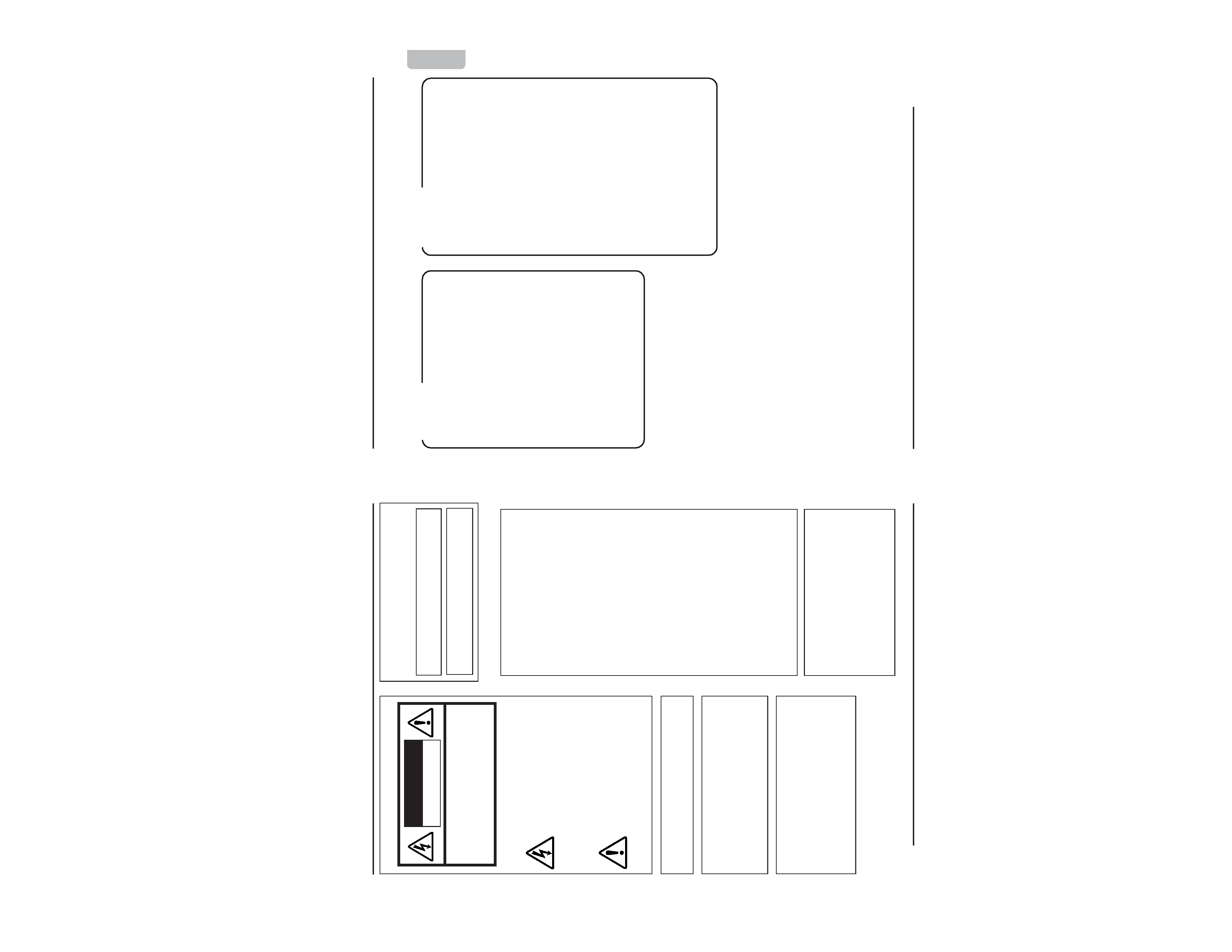
CAUTION:TO REDUCE THE RISK OF ELECTRIC
SHOCK. DO NOT REMOVE COVER (OR
BACK). NO USER-SERVICEABLE PARTS
INSIDE.REFER
SERVICING
TO
QUALIFIED SERVICE PERSONNEL.
The lightning flash wish arrowhead
symbol, within an equilateral triangle is
intended to alert the user to the pres-
ence of uninsulated "dangerous volt-
age" within the product's enclosure that
may be of sufficient magnitude to con-
stitute a risk of electric shock to per-
sons.
The exclamation point within an equi-
lateral triangle is intended to alert the
user to the presence of important op-
erating and maintenance (servicing)
instructions in the literature accompa-
nying the appliance.
RISK OF ELECTRIC SHOCK
DO NOT OPEN
CAUTION
INFORMATION (FOR CANADA)
RENSEIGNEMENT (POUR CANADA)
This Class B digital apparatus complies with
Canadian ICES-003.
Due to design modifications, data given in this
instruction book are subject to possible change
without prior notice.
WARNING:
TO REDUCE THE RISK OF FIRE OR
ELECTRIC SHOCK, DO NOT
EXPOSE THIS APPLIANCE TO
RAIN OR MOISTURE.
AVERTISSEMENT:
POUR EVITER LES RISQUES
D'INCENDIE OU D'ELECTRO-
CUTION,
NE
PAS
EXPOSER
L'APPAREIL A L'HUMIDITE OU A
LA PLUIE.
INFORMATION FOR USA
Cet appareil numérique de la Class B est
conforme á la norme NMB-003 du Canada.
INFORMATION
This equipment has been tested and found to
comply with the limits for a Class B digital device,
pursuant to Part 15 of the FCC Rules.
These limits are designed to provide reasonable
protection against harmful interference in a
residential installation. This equipment generates,
uses, and can radiate radio frequency energy
and, if not installed and used in accordance with
the instructions, may cause harmfull interference
to radio communications. However, there is no
guarantee that interference will not occur in a
particular installation.
If this equipment does cause harmful interference
to radio or television reception, which can be
determined by turning the equipment off and on,
the user is encouraged to try to correct the
interference by one or more of the following
measures:
Reorient or relocate the receiving antenna.
Increase the separation between the equipment
and receiver.
Connect the equipment into an outlet on a circuit
different from that to which the receiver is
connected.
Consult the dealer or an experienced radio/TV
technician for help.
CAUTION
CHANGES
OR
MODIFICATIONS
NOT
APPROVED BY JVC COULD VOID USER'S
AUTHORITY TO OPERATE THE EQUIPMENT.
THIS DEVICE COMPLIES WITH PART 15 OF
THE FCC RULES.
OPERATION IS SUBJECT TO THE FOLLOWING
TWO CONDITIONS: (1) THIS DEVICE MAY NOT
CAUSE HARMFUL INTERFERENCE, AND (2)
THIS
DEVICE
MUST
ACCEPT
ANY
INTERFERENCE RECEIVED, INCLUDING
INTERFERENCE
THAT
MAY
CAUSE
UNDESIRED OPERATION.
E-3
English
Introduction
Contents
Introduction
Features ............................................ 3
Contents ............................................ 3
Safety Precautions ............................ 4
Operating Precautions ...................... 5
Names and Operations of Parts ....... 6
Body Surface ................................ 6
Body Underside ............................ 8
Installation and connection
System diagram ................................ 9
About Connection Cables ............... 10
Mounting the Camera to the
Ceiling ............................................... 11
When installing the Dome camera to
the electrical box ............................. 13
Connection for Adjustment of the
Camera ............................................ 14
Adjusting the Lens and Camera
Angle ............................................... 14
Others
About White-spot correction ............ 16
Specifications .................................. 17
Thank you for purchasing this product.
(These instructions are for TK-C205U and TK-C205E)
Features
The camera uses a high-resolution
380,000 pixel (U type) / 440,000 pixel
(E type), high-sensitivity CCD to
realize high picture quality with
horizontal resolution of 535 TV lines
and S/N 50dB.
Dome-type design allows application
in various locations.
Built-in backlight compensation
feature to improve the quality of video
taken under backlight conditions.
A 4inch square electrical box
compatible
The camera can be set to automati-
cally switch the image to black and
white mode when the brightness of
the subject decreases. This feature
is useful for monitoring in darkness.

E-4
Installation of this unit requires expertise.
Please contact your dealer for details.
The ceiling to mount the camera has to be
strong enough to support the weight of this
product.
If the ceiling is not strong enough, make
sure to apply reinforcement to the ceiling
before installation.
Be sure to tighten the screws and nuts se-
curely, Insufficient tightening may cause the
unit to fall from its mount.
The unit is to be powered by a DC 12 V or
an AC 24 V power supply.
The AC 24 V power supply should conform
to the following:
Class 2 only (U type)
Isolated power supply only (E type)
The rating label is displayed on the under-
side of the body.
JVC will not be liable for any damage re-
sulting from the camera dropping due to
incomplete installation by not following the
installation instructions. Take caution when
performing installation.
Before starting an important recording, be
sure to perform a test recording in order to
confirm that a normal recording is possible.
We do not accept liability for the loss of a
recording in the case of it becoming
impossible to record due to a problem in
the video camera, VCR or video tape.
We do not accept liability for any damage
to the camera in cases when it is dropped
because of incomplete installation due to
not observing the installation instructions
correctly. Please be careful when installing
the camera.
Safety Precautions
Introduction
E-5
English
If a high-intensity object (such as a lamp)
is shot, the image on the screen may have
vertical lines (smear) or blur (blooming) at
its periphery. This is a characteristic of the
CCD, and is not a defect.
Observe the following when carrying out
camera maintenance.
·Turn the power OFF before proceeding
to carry out maintenance.
· Clean the dome cover lens using a lens
wiper cloth (or a tissue).
If it is contaminated seriously, clean the
contaminated part with a cloth (or a tissue)
which has been soaked in a solution of
water and a neutral detergent.
Do not install the unit in an environment
where there is cold air or near the air outlet
of an air conditioner. The dome cover will
cloud as a result.
If the D/N switch is turned on, the mode
changes automatically to black and white
in dark places. As the sensitivity increases,
the image may look grainy and white spots
may appear. When changing modes, bright
portions of image may be emphasized but
this is not a failure of the camera.
Operating Precautions
To save energy, when it is not being used
turn the system's power off.
This camera has been designed for indoor
use. It cannot be used outdoors.
Do not install or use the camera in the fol-
lowing places.
· In a place exposed to rain or moisture.
· In a place with vapor or oil soot, for
example in a kitchen.
· In a temperature outside the operating
temperature range (10°C to 50°C).
· Near a source of radiation, X-rays, strong
radio waves or magnetism.
· In a place where corrosive gasses are
generated.
· In a place subject to vibration.
· In a place with excessive dirt.
If this camera and the cables connected to
this camera are used where there are
strong electromagnetic waves or where
there is magnetism present, for example
near a radio or TV transmitter, power trans-
former or an electric motor, the picture may
produce noise and the colors may be af-
fected.
This camera incorporates an AGC circuit.
As a result, when it is used under low light
conditions, the camera sensitivity is auto-
matically boosted and the picture may look
uneven. This is not a malfunction however.
When this camera is used in the ATW
mode, the recorded colors may be slightly
different from the actual colors due to the
operational principles of the auto-tracking
white balance circuit. This is however not
a malfunction.
E-6
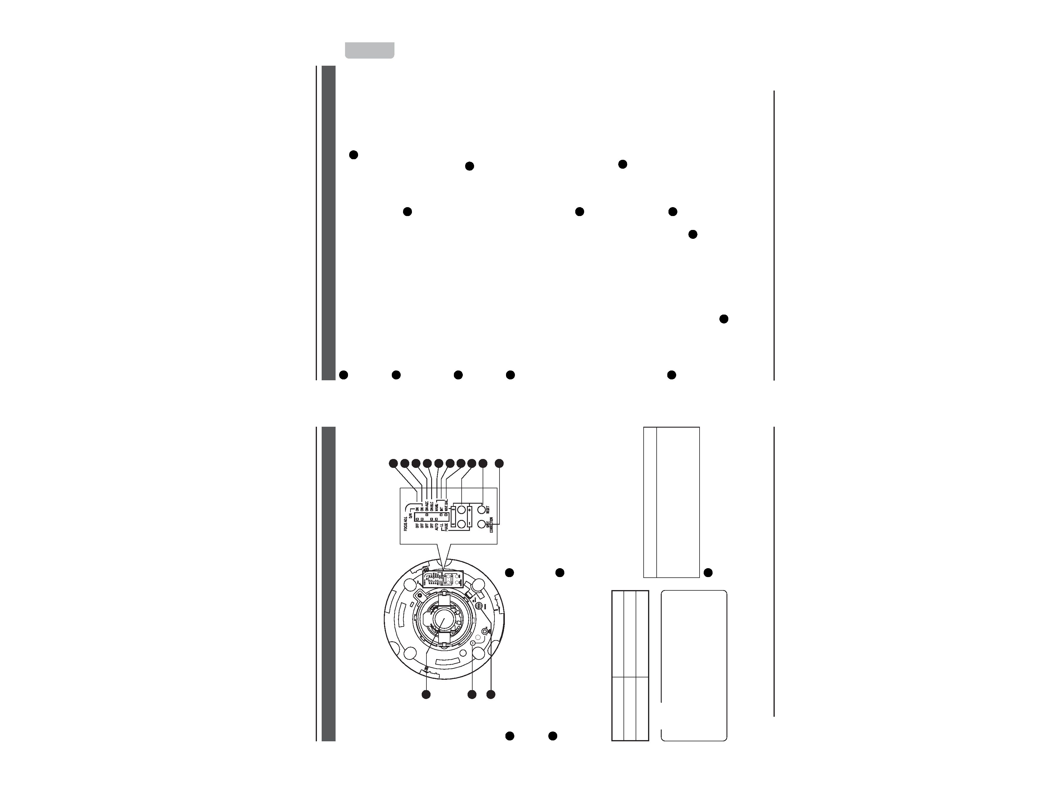
Names and Operations of Parts
Introduction
3
MONITOR terminal (RCA pin)
For connecting a monitor when mount-
ing the camera for adjusting the lens or
determining the camera angle. (High im-
pedance)
4
[D/N - ON/OFF] Easy Day & Night
switch
To capture a subject with continually
changing brightness (day/night), set this
switch to "ON." The camera automatically
captures the image in color when the
subject is bright, and in black and white
mode when it is dark.
(Default setting: OFF)
5
[FOCUS ADJ. - ON/OFF] focus
adjustment switch
When adjusting the focus during
installation, setting this switch to "ON" will
open the iris.
(Default setting: OFF)
(
page 15)
11
9
4
5
6
7
8
12
13
3
2
1
10
Body Surface
View when the dome cover is removed.
For instructions on removing the dome cover, see step 4 of "Mounting the Camera to the
Ceiling". (
page 11)
Turning direction of level
To darken image
Counterclockwise (L side)
To brighten image Clockwise (H side)
1
Head
For adjusting the lens, focus, or camera
angle.
(
page 14 ~ 15)
2
[IRIS LEVEL] Iris level adjustment
For adjusting the level of the automatic
aperture control lens. This adjustment
only needs to be made when required.
Use this to accommodate particular
shooting conditions.
MEMO
·When adjusting the iris level, set the
AGC switch to "OFF". Otherwise, when
the level is turned too far toward L, the
AGC function activates increasing
sensitivity and the picture may look
uneven.
CAUTION
The Easy Day & Night feature on this cam-
era uses a sensitized black and white
mode unlike other black and white surveil-
lance cameras that use infra-red lighting.
E-7
English
6
[AGC - ON/OFF] Auto-gain control switch
Setting this switch to "ON" automatically
increases the sensitivity even when the
brightness of the subject is insufficient.
(Default setting: ON)
7
[BLC - ON/OFF] Backlight
compensation switch
Setting this switch to "ON" opens the iris
even in backlight conditions, making the
subject easier to view.
(Default setting: OFF)
8
[AUTO/MANU] Auto/manual selection
switch
For selecting whether to adjust the white
balance automatically or manually.
(Default setting: AUTO)
9
[INT/LL] Synchronization system
selection switch
This switch sets the synchronizing
system for the camera.
INT:
This is set for internal synchronization
LL (Line Lock):
The camera's vertical synchronization is
locked to the AC 24 V power line fre-
quency.
When switching between multiple cam-
eras using a switcher, selecting this mode
and adjusting the vertical phase can re-
duce the monitor sync disturbances oc-
cur that when the camera image is
switched.
(Default setting: INT)
10
[WHT.BAL/PHASE] adjustment
selection switch
Switch to select the function of the 11
[R/B. +/] adjustment button.
When setting to WHT.BAL:
When the 8 [AUTO/MANU] switch is
set to MANU, the white balance can
be adjusted using the [R/B, +/] button.
When setting to PHASE:
When the 9 [INT/LL] switch is set to
LL, the vertical phase of the line lock
can be adjusted using the [R/B, +/]
button.
(Default setting: WHT.BAL)
11
[R/B, +/] adjustment button
This button is pressed when manually
adjusting the white balance or when
adjusting the vertical phase of the line
lock.
The function of this button is selected
using the 10 [WHT.BAL/PHASE] switch.
When manually adjusting the white
balance:
Press the R button to increase the red
tint and decrease the blue tint.
Press the B button to increase the blue
tint and decrease the red tint.
When adjusting the phase:
Press the + or button to adjust the
phase.
12
[RESET] Reset button
When this button is pressed, the value
of the white balance or phase adjusted
manually is reset to the default value.
When the 10 [WHT.BAL/PHASE] switch
is set to WHT.BAL, the white balance is
reset to the default value. When the
switch is set to PHASE, the phase is
reset to the default value.
13
[SPOT CORRECTION] White-spot
correction button
When this button is pressed, white spots
are corrected.
For instructions on correcting white-
spots, see "About White-spot correction".
(
page 16)