E-1
INSTRUCTIONS
COLOUR VIDEO CAMERA
LWT0276-001A-H
BF LOOK
COLOR
VIDEO
CAMERA
DIGITAL
TK-C1430
TK-C1431
is a registered trademark owned by Victor Company of Japan, Limited.
is a registered trademark in Japan, the U.S.A., the U.K. and many other countries.
© 2005 Victor Company of Japan, Limited.
TK-C1430/TK-C1431
COLOUR
VIDEO
CAMERA
Printed in Thailand
LWT0276-001A-H
®
®

E-2
IMPORTANT SAFEGUARDS
PORTABLE CART WARNING
(symbol provided by RETAC)
S3125A
1. Read all of these instructions.
2. Save these instructions for later use.
3. All warnings on the product and in the operating instructions should be adhered to.
4. Unplug this appliance system from the wall outlet before cleaning. Do not use
liquid cleaners or aerosol cleaners. Use a damp cloth for cleaning.
5. Do not use attachments not recommended by the appliance manufacturer as
they may cause hazards.
6. Do not use this appliance near water - for example, near a bathtub, washbowl,
kitchen sink, or laundry tub, in a wet basement, or near a swimming pool, etc.
7. Do not place this appliance on an unstable cart, stand, or table.
The appliance may fall, causing serious injury to a child or
adult, and serious damage to the appliance.
Use only with a car t or stand recommended by the
manufacturer, or sold with the appliance.Wall or shelf mounting
should follow the manufacturer's instructions, and should use
a mounting kit approved by the manufacturer. An appliance
and cart combination should be moved with care.
Quick stops, excessive force, and uneven surfaces may cause the appliance and
cart combination to overturn.
8. Slots and openings in the cabinet and the back or bottom are pro-vided for
ventilation, and to insure reliable operation of the appliance and to protect it from
overheating, these openings must not be blocked or covered.The openings should
never be blocked by placing the appliance on a bed, sofa, rug, or other similar
surface.
This appliance should never be placed near or over a radiator or heat register.
This appliance should not be placed in a built-in installation such as a bookcase
unless proper ventilation is provided.
9. This appliance should be operated only from the type of power source indicated
on the marking label. If you are not sure of the type of power supplied to your
home, consult your dealer or local power company. For appliance designed to
operate from battery power, refer to the operating instructions.
10.This appliance system is equipped with a 3-wire grounding type plug (a plug
having a third (grounding) pin). This plug will only fit into a grounding-type power
outlet. This is a safety feature. If you are unable to insert the plug into the outlet,
contact your electrician to replace your obsolete outlet. Do not defeat the safety
purpose of the grounding plug.
These are general IMPORTANT SAFEGUARDS and certain items may not apply to all appliances.
E-3
11.For added protection for this product during a lightning storm, or when it is left
unattended and unused for long periods of time, unplug it form the wall outlet and
disconnect the antenna or cable system. This will prevent damage to the product
due to lightning and power-line surges.
12.Do not allow anything to rest on the power cord. Do not locate this appliance
where the cord will be abused by persons walking on it.
13.Follow all warnings and instructions marked on the appliance.
14.Do not overload wall outlets and extension cords as this can result in fire or
electric shock.
15.Never push objects of any kind into this appliance through cabinet slots as they
may touch dangerous voltage points or short out parts that could result in a fire
or electric shock. Never spill liquid of any kind on the appliance.
16.Do not attempt to service this appliance yourself as opening or removing covers
may expose you to dangerous voltage or other hazards. Refer all servicing to
qualified service personnel.
17.Unplug this appliance from the wall outlet and refer servicing to qualified service
personnel under the following conditions:
a. When the power cord or plug is damaged or frayed.
b. If liquid has been spilled into the appliance.
c. If the appliance has been exposed to rain or water.
d. If the appliance does not operate normally by following the operating instruc-
tions. Adjust only those controls that are covered by the operating instructions
as improper adjustment of other controls may result in damage and will often
require extensive work by a qualified technician to restore the appliance to
normal operation.
e. If the appliance has been dropped or the cabinet has been damaged.
f. When the appliance exhibits a distinct change in performance - this indicates
a need for service.
18.When replacement parts are required, be sure the service technician has used
replacement parts specified by the manufacturer that have the same character-
istics as the original part. Unauthorized substitutions may result in fire, electric
shock, or other hazards.
19.Upon completion of any service or repairs to this appliance, ask the service
technician to perform routine safety checks to determine that the appliance is in
safe operating condition.
E-4
WARNING:
TO REDUCE THE RISK OF FIRE OR
ELECTRIC
SHOCK, DO
NOT
EXPOSETHIS APPLIANCE TO RAIN
OR MOISTURE.
Due to design modifications, data given in this
instruction book are subject to possible change
without prior notice.
AVERTISSEMENT:
POUR EVITER LES RISQUES
D'INCENDIE OU D'ELECTRO-
CUTION,
NE
PAS
EXPOSER
L'APPAREIL A L'HUMIDITE OU A LA
PLUIE.
Safety Precautions
E-5
Thank you for purchasing this product.
(These instructions are for TK-C1430E and TK-C1431EG)
Before beginning to operate this unit, please read the instruction manual
carefully in order to make sure that the best possible performance is obtained.
CONTENTS
INTRODUCTION
Features ............................................................................................................................... 6
Operating Precautions ......................................................................................................... 7
Controls, Connectors and Indicators ................................................................................... 8
CONNECTION/INSTALLATION
RM-P2580 System ............................................................................................................. 12
Procedures ........................................................................................................................ 14
Mounting the lens .............................................................................................................. 15
Installing the ferrite core .................................................................................................... 16
Connections on the back ................................................................................................... 16
Mounting the camera ......................................................................................................... 18
Lens adjustment ................................................................................................................ 20
Back focus adjustment ...................................................................................................... 21
Auto white balance control adjustment ............................................................................. 22
MENU SETTING
Setting the menu ............................................................................................................... 23
The flow of menu screen ................................................................................................... 24
SYNC ADJUST Screen ..................................................................................................... 26
ALC SETTINGS Screen .................................................................................................... 26
VIDEO ADJUST Screen .................................................................................................... 31
MODE SELECT Screen .................................................................................................... 32
MOTION DETECT Screen ................................................................................................. 34
COMMUNICATION Screen ............................................................................................... 35
MAINTENANCE Screen .................................................................................................... 35
FACTORY SETTINGS Screen .......................................................................................... 35
BLC EDITTING Screen ..................................................................................................... 36
Manual Adjustment of White Balance ............................................................................... 37
CAMERA TITLE Setting .................................................................................................... 38
Setting the MOTION DETECT Function ........................................................................... 39
Output of Black-White/Colour switching signal ................................................................. 40
Control by Black-White/Colour switching signal from the outside .................................... 41
White spot compensation .................................................................................................. 42
OTHERS
Specifications ..................................................................................................................... 43

E-6
A DSP (Digital Signal Processor) features
a Extended Dynamic Range (ExDR) and
enables to shoot both bright and dark
locations.
The use of a CCD with a SENSE UP (X32)
function realized the minimum luminous
flux density for subject of 0.9 lx (F1.2,
50%, AGC 20dB) and 0.03 lx (at SENSE
UP (X32)). Furthermore, we realized 0.03
lx (F1.2, 50% AGC 20dB) thanks to the
function of B/W mode.
A motion detector function detects the
motion inside an image and emits alarm
signals.
The equipped Y/C terminals and RS-
422A/RS-485 terminals allow intended
compatibility with diversified systems.
Day/Night surveillance
When the light is low, the camera pictures
can be switched automatically to black
and white pictures.
Electronic zoom
The 10x electronic zoom allows
monitoring in far greater detail.
Features
Before starting an important recording,
be sure to perform a test recording in
order to confirm that a normal
recording is possible.
We do not accept liability for the loss of
a recording in the case of it becoming
impossible to record due to a problem
in the video camera, VCR or video tape.
We do not accept liability for any
damage to the camera in cases where
it is dropped because of bad installation
due to failure to observe the installation
instructions correctly. Please be careful
when installing the camera.
The motion detector is not a feature
which prevents theft, fire, etc. Even if
an accident should occur resulting in
damage, we do not accept any liability.
INTRODUCTION
Characters and symbols used in this instruction manual.
CAUTION : Cautionary notes concerning operation of the unit.
MEMO
: Reference such as restrictions of features, etc.
: Reference page or item.
E-7
To save energy, when it is not being used
turn the system's power off.
This camera has been designed for indoor
use. When you use it outdoors, be sure
to use a housing or the like.
Do not install or use the camera in the
following places.
· In a place exposed to rain or moisture.
· In a place with vapor or oil soot, for
example in a kitchen.
· When the ambient temperature rises
above or falls below the acceptable
range (from 10°C to 50°C).
· Near a source of radiation, X-rays,
strong radio waves or magnetism.
· In a place subject to vibration.
· In a place with excessive dirt.
If this camera and the cables connected
to this camera are used where there are
strong electromagnetic waves or where
there is magnetism present, for example
near a radio or TV transmitter, power
transformer or an electric motor, the picture
may produce noise and the colours may
be affected.
This camera incorporates an AGC circuit.
As a result, when it is used under low light
conditions, the camera sensitivity is
automatically boosted and the picture may
look uneven. However, this is not a
malfunction.
While the AGC is activated, if transceiver
which causes strong electromagnetic
wave is at close distance, picture might
suffer from beat.
So please use the camera more than three
meters from such transceivers.
When this camera is used in the ATW
mode, the recorded colours may be slightly
different from the actual colours due to the
operational principles of the auto-tracking
white balance circuit. However, this is not
a malfunction.
If a high-intensity object (such as a lamp)
is shot, the image on the screen may have
vertical lines (smear) or blur (blooming)
at its periphery. This is a characteristic of
the CCD, and is not a defect.
Operating Precautions
Observe the following when carrying out
camera maintenance.
·Turn the power OFF before proceeding
to carry out maintenance.
If it is contaminated seriously, clean the
contaminated part with a cloth (or a
tissue) which has been soaked in a
solution of water and a neutral detergent.
The unit is to be powered by a DC 12 V
or an AC 24 V power supply. (TK-C1430E)
The AC 24 V power supply should conform
to the following: Isolated power supply
only
TK-C1431EG: Connect the power cable to
the commercial power supply of 220V
240V.
Caution for operating the video iris lens.
If the video iris lens is set to an extremely
low level, a malfunction such as the
hunting phenomenon where the iris opens
and closes in voluntary can occur.
In such a case, first set the "LEVEL"
potentiometer on the lens to the H position
(iris open), and then adjust it to an optimum
level. (
page 20)
The cable stopper on the terminal block
can come off sometimes. Therefore, be
sure to take enough time and fix the cable
securely.
When a highly bright subject is shot,
sometimes undulations can be observed
on the ver tical lines of the subject.
However, this phenomenon is peculiar to
the unit and is not a sign of malfunction.
The beat may sometimes appear on the
screen if gain is raised when the line lock
is in use, but the phenomenon takes place
due to the fluctuation of power frequency
and is not a malfunction.
You may hear some noise when the
screen is switched between the colour
and the black and white mode, because
the optical filter moves. Also, black vertical
bands will appear on the screen.
Set the Iris Selector switch to VIDEO to
use the manual lens.
E-8
INTRODUCTION
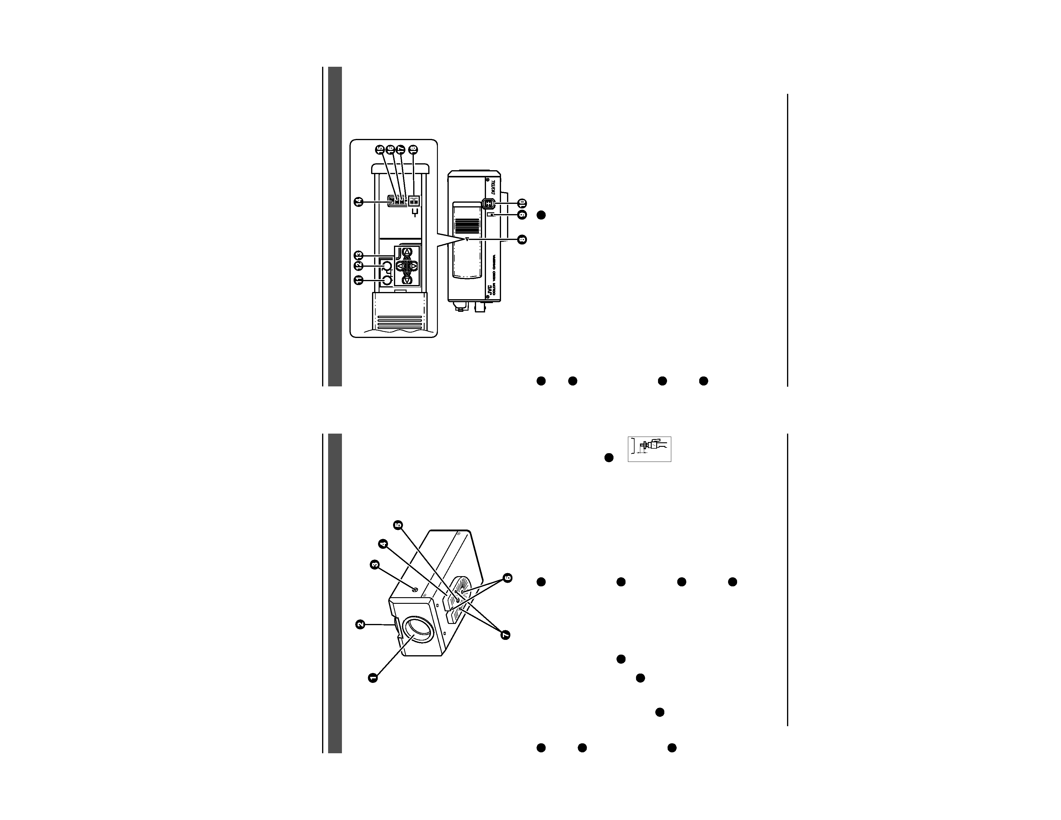
1 Lens mount
To attach the lens.
This is applicable to both C-mount lenses
and CS-mount lenses.
2 Back focus adjustment ring
Adjusting the back focus during lens
installation.
When readjustment is required, loosen
the locking screw
3
by turning it
counterclockwise and turn the back focus
adjustment ring 2 .
After the adjustment, tighten the locking
screw 3 again.
3 [BF LOCK] Back focus locking screw
This serves to fix the back focus-adjusting
ring.
4 Camera-mounting bracket
The bracket has been attached on the
bottom of the camera before shipment. It
can also be attached on the top
according to the circumstance.
To re-attach the bracket use the threaded
holes at the top, with the camera
mounting bracket fixing screws 7 .
5 Camera-mounting screw
hole (1/4 inch)
Use this hole when mounting
the camera onto a fixer, pan/
tilt unit, and the like. (Use a
screw shorter than 7 mm.)
6 Rotation-preventive hole
Make use of this rotation-preventive hole
to prevent any fall when mounting the
camera. Always make sure that the
camera is securely mounted.
7 Camera mounting bracket fixing screws
(×2: M2.6 × 6 mm)
Be sure to use a 6 mm long screw.
MAX.
7mm
Controls, Connectors and Indicators
E-9
8 Cover
The cover slides open when push to the
left.
9 [VIDEO/DC] Iris Selector Switch
This should be set according to the type
of lens if an automatic iris control lens is
used.
VIDEO: In case of lens with EE amp built-
in.
DC:
In case of lens without EE amp
built-in.
(DC: At time of factory shipment)
10 [IRIS] Iris Terminal
This is connected to an automatic iris
control lens.
(
Page 15)
11 [MENU] Menu Button
When pressed, a menu screen is brought
up.
(
Page 23)
ON
SIMPLEX
ON
LL
SET
AWC
MENU
CAMERA
SETUP
EXT TERM-OFF
INT/GL
DUPLEX
RX TERM-OFF
NOT USED
VIDEO
DC
IRIS
12 [SET/AWC] Set. Auto White Control
Button
SET: Press this button to display a sub-
menu.
(
Page 23)
AWC: If this button is kept pressed for
more than 1 second, a one-push-
auto-white-balance function works
and sets the white balance. Once
it is set, even if colour temperature
changes, white balance does not
change. It is also possible to make
fine adjustments on the set white
balance.
(
Page 22)