TD-W354B/J
INSTRUCTIONS
DOUBLE CASSETTE DECK
DOUBLE
CASSETTE
DECK
TD-W354 B/J
For Customer Use:
Enter below the Model No. and Serial No.
which are located on the rear of the cabinet.
Retain this information for future reference.
Model No.
Serial No.
a
Area suffix
B .................... U.K.
J .....................
STANDBY / ON
POWER
REC/REC MUTE PAUSE
MUSIC SCAN
COUNTER RESET
COMPU CAL
MUSIC SCAN
COUNTER RESET
PHONES
MIX LEVEL
MIC
PITCH CONTROL
MIN
MAX
SLOW
FAST
DECK A
DOLBY NR REVERSE
MODE
A B SYNCHRO DUBBING
B
C
NORM SPEED HIGH SPEED
PLAY
PLAY
MIN
MAX
1
2
5
3
4
6
INPUT LEVEL
MIN
MAX
1
2
5
3
4
6
7
8
9
INPUT LEVEL
TD-W354
ON
OFF
DOUBLE CASSETTE DECK
DOLBY B-C NR HX PRO
POWER
REC/REC MUTE PAUSE
MUSIC SCAN
COUNTER RESET
COMPU CAL
MUSIC SCAN
COUNTER RESET
PHONES
MIX LEVEL
MIC
PITCH CONTROL
MIN
MAX
SLOW
FAST
DECK A
DOLBY NR REVERSE
MODE
A B SYNCHRO DUBBING
B
C
NORM SPEED HIGH SPEED
PLAY
PLAY
MIN
MAX
1
2
5
3
4
6
INPUT LEVEL
MIN
MAX
1
2
5
3
4
6
7
8
9
INPUT LEVEL
TD-W354 DOUBLE CASSETTE DECK
DOLBY B-C NR HX PRO
AUTO REVERSE
COMPU CALIBRATION
B
REC/PLAYBACK
PITCH CONTROL
A
PLAYBACK
AUTO REVERSE
COMPULINK
Component
AUTO REVERSE
COMPU CALIBRATION
B
REC/PLAYBACK
PITCH CONTROL
A
PLAYBACK
AUTO REVERSE
COMPULINK
Component
STANDBY
STANDBY
(B version)
(J version)
U.S.A.
WARNING:
TO REDUCE THE RISK OF FIRE OR ELECTRIC SHOCK,
DO NOT EXPOSE THIS APPLIANCE TO RAIN OR MOIS-
TURE.
IMPORTANT (In the United Kingdom)
Mains Supply (AC 230 V
z, 50 Hz only)
DO NOT cut off the mains plug from this equipment. If the
plug fitted is not suitable for the power points in your home or
the cable is too short to reach a power point, then obtain an
appropriate safety approved extension lead or consult your
dealer.
BE SURE to replace the fuse only with an identical approved
type, as originally fitted and to replace the fuse cover.
If nonetheless the mains plug is cut off ensure to remove the
fuse and dispose of the plug immediately, to avoid a possible
shock hazard by inadvertent connection to the mains supply.
DO NOT make any connection to the terminal which is
marked with the letter E or by the safety earth symbol or
coloured green or green-and-yellow.
The wires in the mains lead on this product are coloured in
accordance with the following code:
Blue to N
(Neutral) or Black
Brown to L
(Live) or Red
As these colours may not correspond with the coloured mark-
ings identifying the terminals in your plug proceed as follows:
The wire which is coloured blue must be connected to the
terminal which is marked with the letter N or coloured black.
The wire which is coloured brown must be connected to the
terminal which is marked with the letter L or coloured red.
IF IN DOUBT-CONSULT A COMPETENT ELECTRICIAN.
Please study this instruction manual carefully before starting
to operate the unit, in order to use the unit correctly. We take
no responsibility for any problems resulting from misuse of
this unit by operating this equipment other than instructed in
this manual.
WARNING (In the United Kingdom)
Pre-recorded tapes, records or discs should not be
re-recorded without the consent of the owners of copyright in
the sound recording and in any copyright musical or literary
work embodied in that recording as this constitutes an
infringement of copyright.
INFORMATION (FOR U.S.A.)
This equipment has been tested and found to comply with the
limits for a Class B digital device, pursuant to Part 15 of the
FCC Rules. These limits are designed to provide reasonable
protection against harmful interference in a residential
installation. This equipment generates, uses, and can radiate
radio frequency energy and, if not installed and used in
accordance with the instructions, may cause harmful
interference to radio communications.
However, there is no guarantee that interference will not occur
in a particular installation. If this equipment does cause harmful
interference to radio or television reception, which can be
determined by turning the equipment off and on, the user is
encouraged to try to correct the interference by one or more of
the following measures:
- Reorient or relocate the receiving antenna.
- Increase the separation between the equipment and receiver.
- Connect the equipment into an outlet on a circuit different
from that to which the receiver is connected.
- Consult the dealer or an experienced radio/TV technician
for help.
CAUTION
``TO REDUCE THE RISK OF ELECTRIC SHOCK
DO NOT REMOVE COVER (OR BACK)
NO USER SERVICEABLE PARTS INSIDE
REFER SERVICING TO QUALIFIED SERVICE PERSONNEL.''
RISK OF ELECTRIC SHOCK
DO NOT OPEN
The lightning flash with arrowhead symbol, within
an equilateral triangle, is intended to alert the
user to the presence of uninsulated ``dangerous
voltage'' within the product's enclosure that may
be of sufficient magnitude to constitute a risk of
electric shock to persons.
The exclamation point within an equilateral
triangle is intended to alert the user to the
presence of important operating and maintenance
(servicing) instructions in the literature
accompanying the appliance.
2
id8/i10371/ 09/23/99 Page 2
INTRODUCTION
Thank you for purchasing a JVC product. Read this instruction
book carefully before operating to be sure of getting optimum
performance and longer service life from the unit.
CONTENTS
Features .................................................................................... 3
Auto reverse operation ............................................................. 3
Cautions .................................................................................... 3
Connections .............................................................................. 5
Cassette loading ....................................................................... 5
Names of parts and their functions .......................................... 6
Playback ................................................................................... 7
Multi music scan ....................................................................... 8
Recording ................................................................................. 8
Compu link control system ..................................................... 11
Dubbing .................................................................................. 12
Maintenance ........................................................................... 13
Troubleshooting ...................................................................... 14
Specifications .......................................................................... 15
FEATURES
1.
Double auto-reverse mechanism for recording/playback
in deck B and playback in deck A
2.
The COMPU CAL function automatically sets the
record/playback flat frequency characteristics and opti-
mal record/playback tape sensitivity for bringing out
maximum tape performance.
3.
Full logic mechanism
4.
Dolby* HX PRO headroom extension
5.
DolbyB&C noise reduction system
6.
DDRP (Dynamics Detection Recording Processor) com-
patibility
The DDRP function is possible only when used with a suit-
able JVC CD player.
7.
2-color FL peak level indicator
8.
Digital tape counter respectively for deck A and deck B
9.
Synchro start (normal-/high-speed) dubbing
10. Auto tape select mechanism (decks A and B)
11. Multi music scan mechanism for either direction
``Under License of Staar S.A., Brussels, Belgium''
12. PITCH control
13. Microphone mixing is possible
14. COMPU LINK-3 compatible
* Dolby noise reduction and HX Pro headroom extension
manufactured under license from Dolby Laboratories
Licensing Corporation. HX Pro originated by Bang & Olufsen.
* ``DOLBY'', the double-D symbol
and ``HX PRO'' are trade-
marks of Dolby Laboratories Licensing Corporation.
COMPU LINK control system is the convenient system using
COMPU LINK-3/SYNCHRO terminals on the rear panel.
(See page 5 and 11.)
This product can be combinated with a DDRP (DYNAMICS
DETECTION RECORDING PROCESSOR) system (compact
disc player + cassette deck, etc.) to enable setting the opti-
mum recording level automatically. Refer to these instruc-
tions for details.
AUTO REVERSE OPERATION
The auto reverse operation of this unit turns the tape transport
over to the reverse of forward direction automatically when the
tape reaches its end during recording or playback.
·
Because of cassette shell construction, a tape recorded in the
forward direction should be played back in the same direction
to obtain stable sound reproduction.
·
During recording, auto reverse can be activated only from the
forward to the reverse direction. For good sound quality and to
avoid accidental erasure of previously recorded material,
always start recording with the side A of the tape facing out.
CAUTIONS
1. Prevention of Electric Shocks, Fire Hazards and Damage
1) Even when the POWER switch is set to STANDBY, a very
small current will flow. To save power and for safety when
not using the unit for an extended period of time, disconnect
the power cord from the household AC outlet. (for the J ver-
sion)
Set the
POWER switch to the OFF position when not in
use. (for the B version)
2) Do not handle the power cord with wet hands.
3) When unplugging from the wall outlet, always grasp and pull
the plug, not the power cord.
4) Consult your nearest dealer when damage, disconnection, or
contact failure is found with the cord.
5) Do not bend the cord sharply, or pull or twist it.
6) Do not modify the power cord in any manner.
7) Do not remove screws to disassemble the unit and do not
touch anything inside the unit.
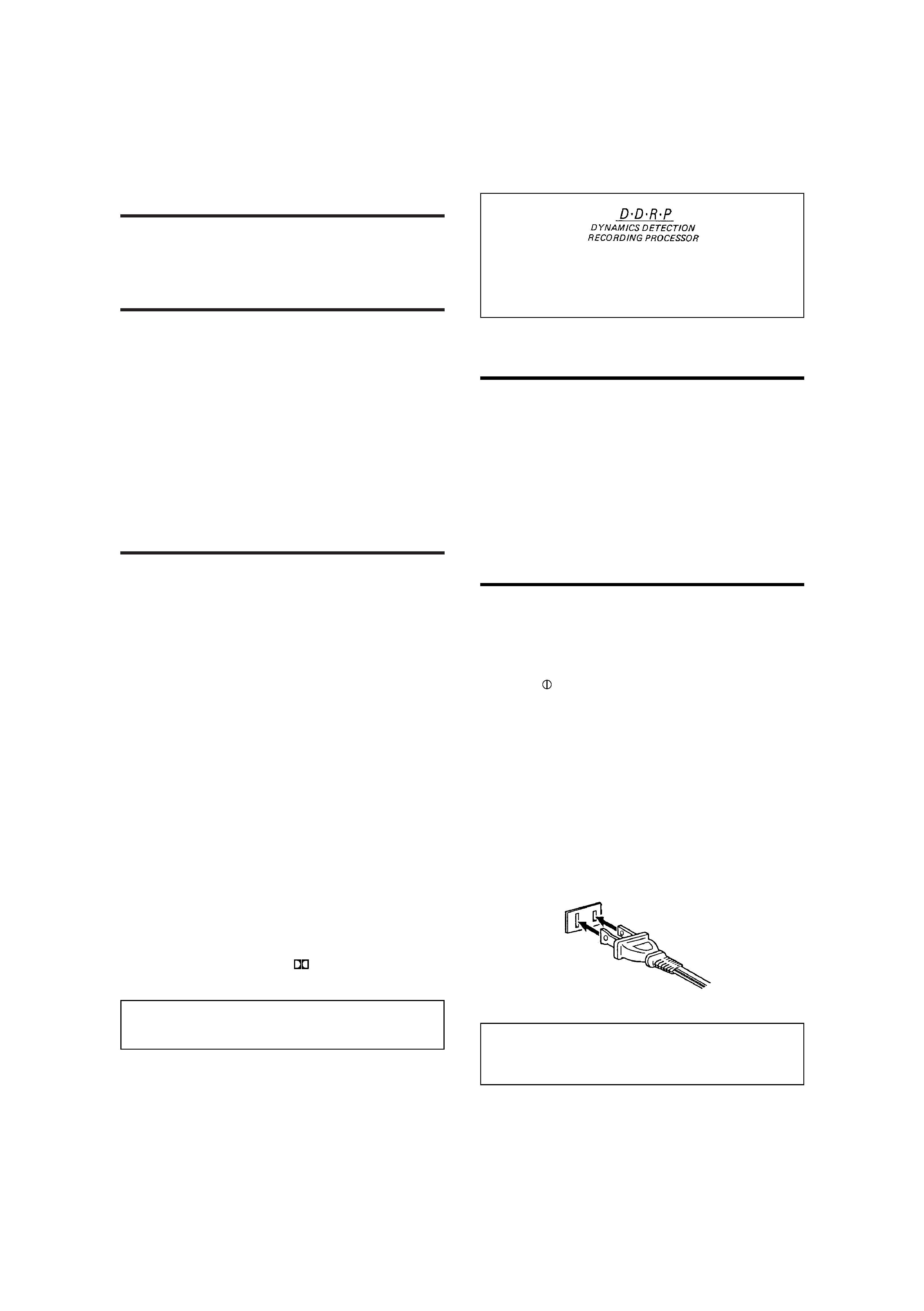
8) AC power cord (For the J version only)
The AC power cord of this unit has certain one-way direction
connections to prevent electric shock. Refer to the illustration
for correct connection. (Fig. 1)
Fig. 1
(For CANADA)
CAUTION
TO PREVENT ELECTRIC SHOCK, MATCH WIDE BLADE
OF PLUG TO WIDE SLOT, FULLY INSERT.
3
id8/i10371/ 09/23/99 Page 3
(Pour le CANADA)
ATTENTION
POUR EVITER LES CHOCS ELECTRIQUES, INTRODUIRE
LA LAME LA PLUS LARGE DE LA FICHE DANS LA
BORNE CORRESPONDANTE DE LA PRISE ET POUSSER
JUSQU'AU FOND.
9) Do not insert any metallic objects into the unit.
10) Unplug the power cord when there is a possibility of light-
ning.
11) If water gets inside the unit, unplug the power cord from the
outlet and consult your dealer.
12) Do not block the ventilation holes of the unit so that heat can
escape. Do not install the unit in a badly ventilated place.
13) Be sure to unplug the power cord from the outlet when going
out or when the unit is not in use for an extended period of
time.
2. Installation
1) Avoid placing the unit on or adjacent to an amplifier, to pre-
vent hum from being produced by some types of amplifiers.
Move the unit to a place not affected by the amplifier. Keep
the unit as far as possible from a TV set.
2) Avoid installing the unit in a location subject to ambient tem-
peratures exceeding 40 °C (104 °F) (e.g. direct sunlight,
near heaters, etc.) or less than 0 °C (32 °F), excessive
humidity, dust or vibrations.
3) If this set is moved suddenly from a cold place (0 °C) to a
warm place, it may not function properly because of moisture
generated inside the unit. The unit will function properly
30 minutes after being moved.
3. Cleaning the cabinet
Never use benzine or thinner for cabinet cleaning as they may
damage the surface finish.
4. Cassette tape
1) Loose tape may become tangled in the tape transport
mechanism. Remove slack by winding the tape with a pen-
cil.
(Fig. 2)
Fig. 2
Turn the pencil to tighten the tape.
2) The use of C-120 (120 minutes turn around) or thinner tape
is not recommended, since characteristic deterioration may
occur.
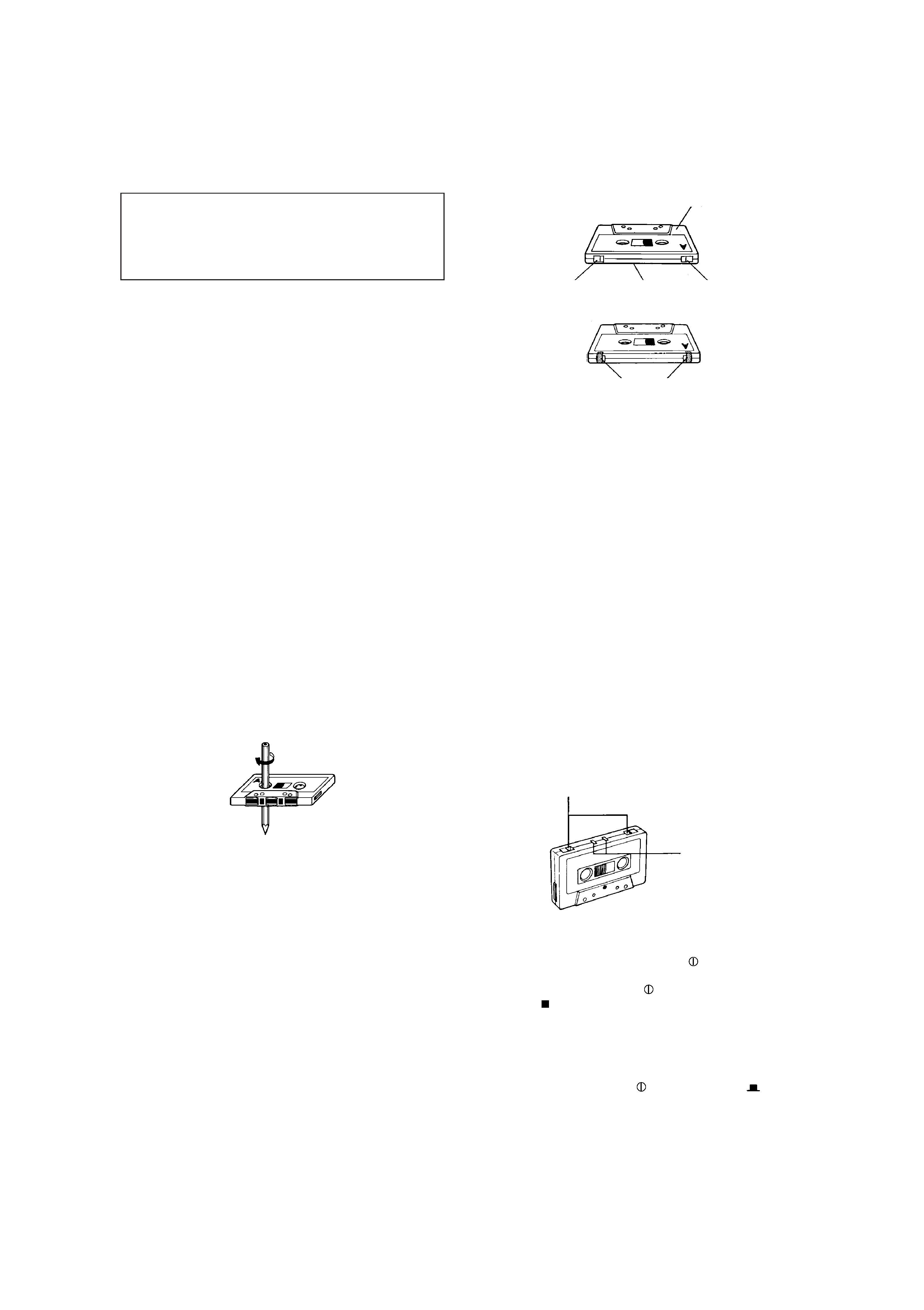
3) To prevent recordings from being erased accidentally,
remove the tab(s) with a screwdriver. Reseal the slots with
adhesive tape to erase and re-record after the tabs have
been broken off.
Fig. 3
4) Do not store cassette tapes where there is a magnetic field
(e.g. near a TV, etc.) or in a place subject to high tempera-
tures or humidity.
5. Auto tape select mechanism (decks A and B)
This deck has an Auto Tape Select mechanism which distin-
guishes between different types of tape from holes in the
cassette. After the type of tape has been detected, bias and
equalization are set to be suitable for the tape.
·
Cassettes with the detection holes:
Metal tape (EQ: 70µs) ........................................ Type IV
CrO2 (chrome) tape (EQ: 70µs) .......................... Type II
·
Cassettes without the detection holes:
Normal tape (EQ: 120µs) ..................................... Type I
Some earlier types of metal and CrO2 (chrome) tapes may
not be provided with the detection holes. Avoid using such
tapes, since correct equalization characteristics cannot be
obtained. Also do not use ferrochrome tapes whose charac-
teristics do not match this unit.
6. Operations
1) Noise may be generated if the
POWER switch is
switched OFF with the deck set to playback or recording
mode. Before switching the
POWER switch OFF, confirm
that the
(stop) button has been pressed. (B version)
2) Many operations of this unit are performed under the control
of a microcomputer. Use the unit only after carefully studying
the descriptions and cautions in each item. If operations are
done incorrectly, the unit may stop functioning correctly. If
this happens, for the J version, unplug the power cord and
for the B version, set the
POWER switch to
OFF, so
that the unit can function correctly.
Side ``A''
Tab ``B''
Side ``B''
Tab ``A''
Adhesive tape
CrO2 tape detection
holes
Metal tape detection holes
4
id8/i10371/ 03/18/97 Page 4
CONNECTIONS
·
Do not switch the power on until all the connections are com-
pleted.
·
Insert the plugs firmly, or poor contact will result, causing
noise.
·
When the pin-plug cords are employed, always connect the
white plug to the left channel terminal. This helps to avoid
reversed connections.
·
When using the Compu Link Control System version 3, do not
connect the power cord to the SWITCHED AC OUTLET of an
amplifier or receiver. In the B version, turn the deck
POWER switch ON. Otherwise, the automatic power on/
STANDBY function cannot be carried out.
1. Connection to a stereo amplifier
Note:
When installing the deck, be sure to install at a distance from
your amplifier. If they are stacked, noise (hum) may occur.
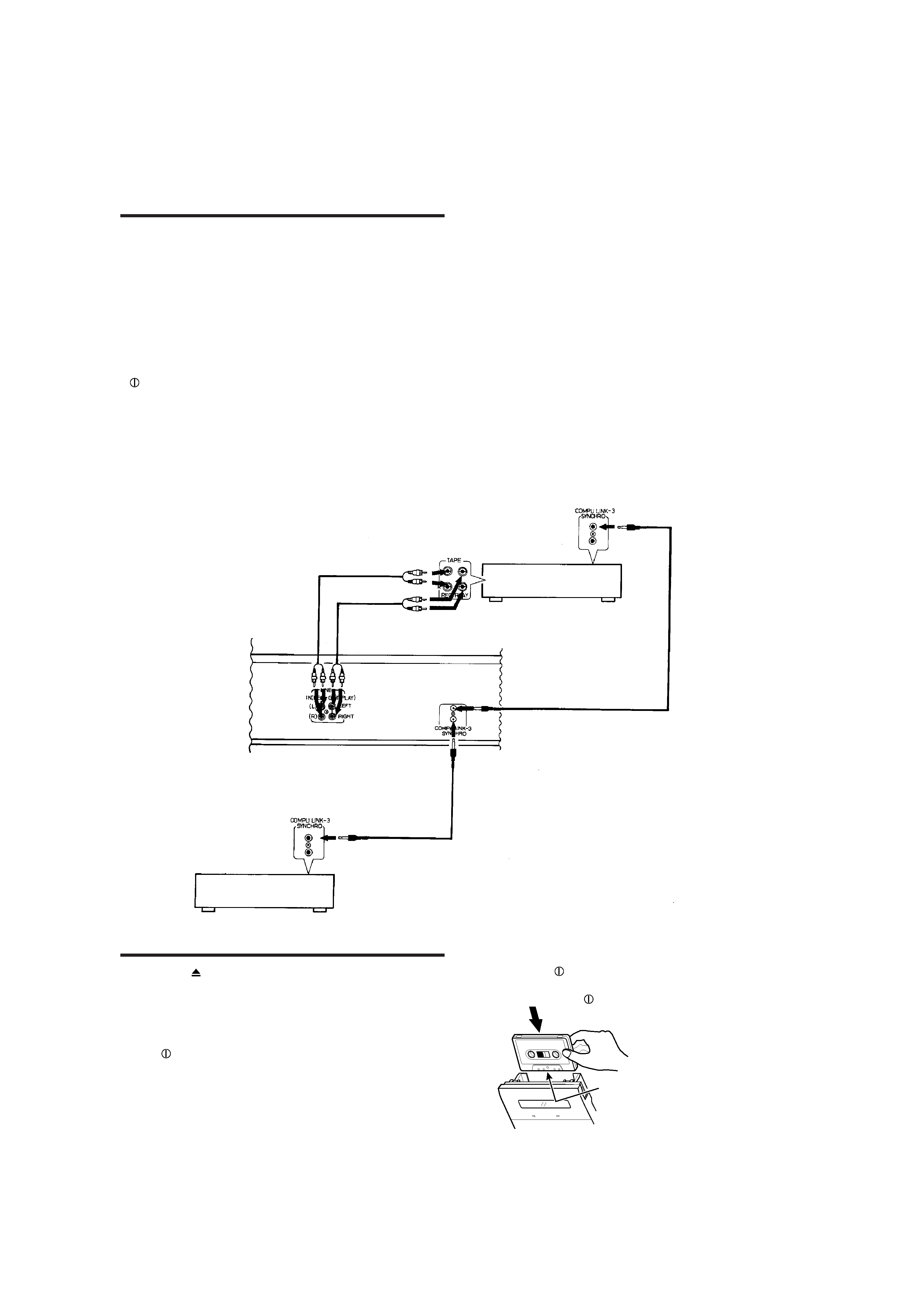
2. Remote cable connection for COMPU LINK
·
By connecting a remote cable, COMPU LINK functions (auto-
matic power on/STANDBY, automatic source selection, syn-
chronized recording and DDRP recording) can be performed.
In this time the provided pin-plug cords must be also con-
nected.
·
When making synchronized recording with a CD player, con-
nect the remote cable to the COMPU LINK-1/SYNCHRO or
COMPU LINK-3/SYNCHRO jacks.
Notes:
1. When making synchronized recordings, only a single deck
should be connected to the amplifier.
2. If a component is not a JVC COMPU LINK component,
bypass it when making the remote cable connections.
3. This deck can be connected with an amplifier and a CD
player which have the COMPU LINK-1/SYNCHRO jacks for
COMPU LINK performance. (See page 11 for details.)
CASSETTE LOADING
1. Press the
(eject) button to open the cassette holder.
2. Load a cassette as shown.
3. Press the cassette holder to close it. Be sure to obtain the
click sound to close the holder securely.
Notes for the B version:
·
If the
POWER switch is set to OFF while the tape is mov-
ing, you might not be able to remove the cassette. If this hap-
pens, switch the power on again before attempting to remove
the cassette.
·
Setting the
POWER switch to OFF during playback or
recording may cause a malfunction. Always stop playback
before setting the
POWER switch to OFF.
Pin-plug cords (provided)
Stereo amplifier
Remote cable (provided)
Remote cable (provided with CD player)
CD player
A
AUTO REVERSE
Load the cassette with the
tape-exposed edge down.
5
id8/i10371/ 09/23/99 Page 5