!"=gs`=
!
!"#$%&'()*+,!"-./%012'345
!"#$%&'()*+,=gs`=
!"#$%
INSTRUCTIONS
MANUAL DE INSTRUCCIONES: SYSTEMA DE ALTAVOZ DE SATÉLITE
INSTRUÇÕES: SISTEMA DE ALTO-FALANTES SATÉLITE
SATELLITE SPEAKER SYSTEM
Thank you for purchasing JVC speakers.
Before you begin using them, please read the instructions care-
fully to be sure you get the best possible performance. If you have
any questions, consult your JVC dealer.
Le estamos muy agradecidos por haber adquirido estos altavoces
de JVC.
Antes de utilizarlos, sirvase leer las instrucciones detenidamente
a fin de obtener el mejor rendimiento posible. Si tienenaluna
pregunta, acuda a su agente de JVC.
Gratos pela aquisição dos altifalantes JVC.
Antes de desfrutar este sistema, leia atentamente as instruções
que o acompanham, de modo a assegurar-se da obtenção do
melhor desempenho possível. Caso surjam dúvidas concernentes
a este sistema, consulte o seu agente JVC.
SP-X103 Consists of SP-X103F and SP-X103C
LVT1032-002A
[US]
Consta de SP-X103F y SP-X103C
Constituído por SP-X103F e SP-X103C
=SP-X103F=
=SP-X103C
!"#$%&'
JVC
.
.
JVC
.
WHOJ« WUL« q
UIK*«
s
nQ
SP-X103F
Ë
SP-X103C
2
Center speaker (1)
Satellite speakers (4)
I Types of speaker systems
SP-X103F
SP-X103C
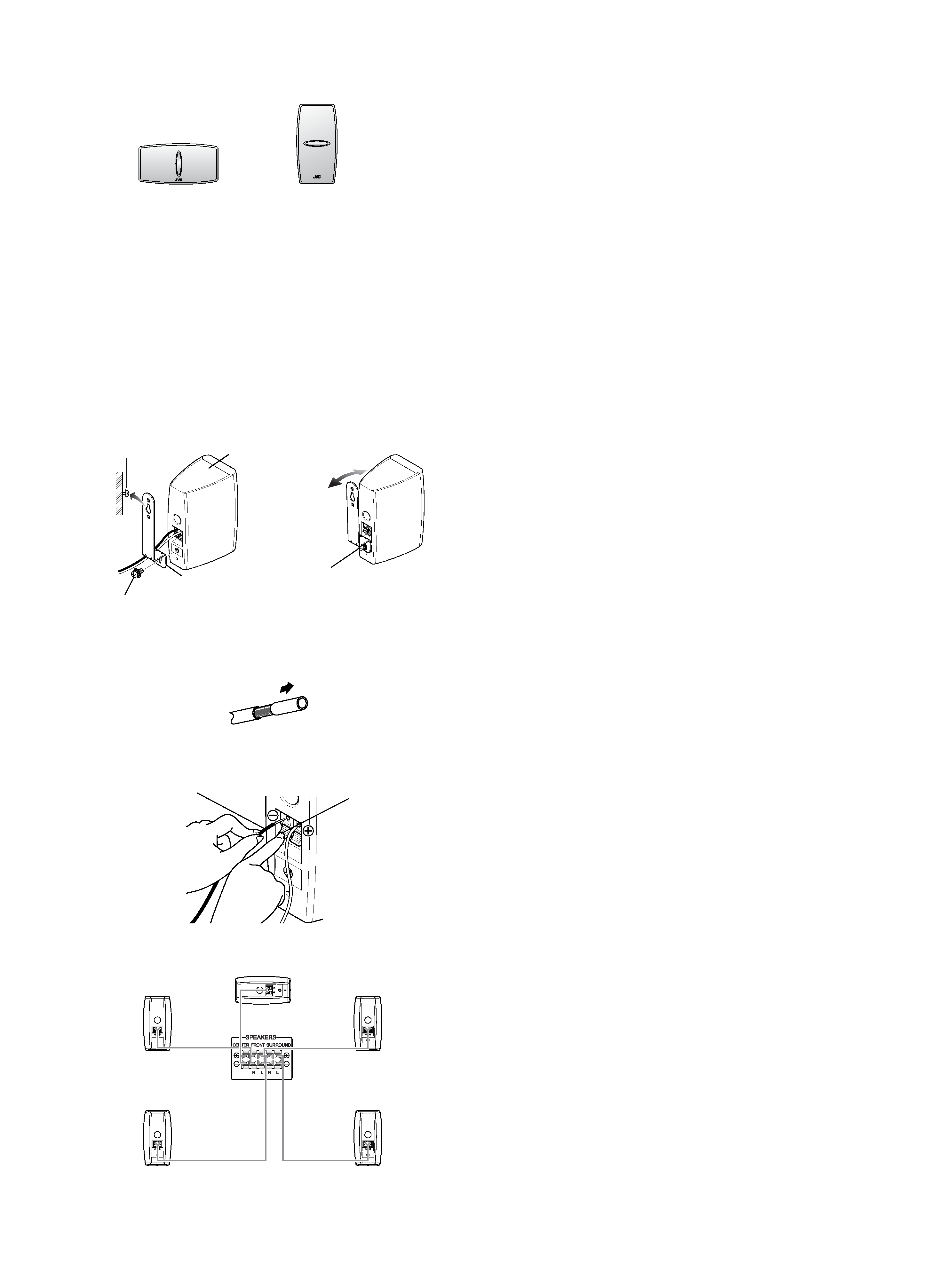
I Precaution for when hanging the speaker system on walls
and pillars
G Check and make sure that the walls and pillars are strong enough to
enable the installation of the speaker system. If they are weak, it is
imperative that you reinforce them.
If walls or pillars with insufficient strength are employed, the speaker
system may fall, resulting in injury and/or trouble.
G Installing the provided wall hanging bracket.
1) Connect the speaker cord.
2) Install the provided wall hanging bracket onto the speaker body with
the screw that is also provided.
3) Adjust the angle of the speaker body.
4) Use the hole of wall hanging bracket and hang it on a nail or a wooden
screw of the wall.
You can adjust the angle by loosening the screw.
Tighten the screw after adjusting the angle.
Black
Press
Center speaker
Satellite
(Front, left)
Satellite
(Front, right)
Speaker terminals
on the amplifier
SP-X103F
SP-X103F
SP-X103C
SP-X103F
SP-X103F
I CONNECTION
1. If cords are covered with insulation, twist the core of the cord at the end
of each cord,then remove the insulation.
2. Insert it into the hole while pressing down the terminal lever.
I CONNECTION
· Connect the LEFT speaker terminals of the amplifier to the terminals of
the LEFT speaker and RIGHT to RIGHT and CENTER to CENTER using
the attached speaker cords as shown in the figure making sure polarity is
correct; (+) to (+) and () to (). Connect the black speaker wire to the
() terminal.
· Turn off power to the whole system before connecting the speakers to
the amplifier.
· The nominal impedance of the SP-X103 is 8
. Select for use an amplifier
to which a speaker system with the load impedance of 8
can be
connected.
· The maximum power handling capacity of the SP-X103 is 100 W.
Excessive input will result in abnormal noise and possible damage. In
cases where the signals described below are applied to the speakers,
even if the signals are below the maximum allowable input, they may
cause an overload and burn the wiring of the speakers. Be sure to lower
the amplifier volume beforehand.
1) Noise during FM tuning.
2) High level signals containing high frequency components produced
by a tape deck in the fast forward mode.
3) Click noise produced when turning power of other components on and
off.
4) Click noise produced when connecting or disconnecting cords with
the power on.
5) Click noise produced when the cartridge is replaced with the power
on.
6) Click noise produced when operating amplifier switches.
7) Continuous high frequency oscillation or high pitch electronically
produced musical instrument sound.
8) Howling when using a microphones.
I SPEAKER FOR A/V COMBINATION
SP-X103 have a magnetically-shielded design for placement adjacent to
TVs and monitors without causing color aberrations. However, color may be
affected as a result of how the speaker system is installed. Therefore, be
careful of the following:
1. When placing these speakers near a TV set, turn off the TV's main power
switch or unplug it before installing the speakers.
Wait at least 30 minutes after the system is installed before turning on
the TV's power.
2. If another speaker system has been set up near the TV set, that system
may cause color unevenness in the TV's picture.
3. In spite of the shielded design of these speakers, some types of TV's
may be affected by them. If this happens, move the speakers a short
distance form the TV set.
I SPECIFICATIONS
Type
: 1-way 2-speaker Bass-Reflex Type
(Magnetically-shielded type)
Speakers
: 5.5 cm cone
× 2
Power Handling Capacity
: 100 W
Impedance
: 8
Frequency Range
: 80 Hz 20 000 Hz
Sound Pressure Level
: 81 dB/W·m
Dimensions (W
× H × D)
Satellite speakers
: 82 mm
× 159 mm × 111 mm
Center speaker
: 158 mm
× 87 mm × 111 mm
Mass
: 0.77 kg each
Accessories
: Speaker cord
(10 m) .................................. 2
(5 m) .................................... 3
Bracket ................................ 2
Screw (M5
× 10 mm) ........... 2
Speaker body
Screw (M5
× 10 mm)
(provided)
Wall hanging bracket
Screw (not provided)
Satellite
(Surround, left)
Satellite
(Surround, right)
ENGLISH