SERVICE MANUAL
SERVICE MANUAL
HOME THEATER DVD-AUDIO/VIDEO RECEIVER
No.21180
Oct. 2002
COPYRIGHT
2002 VICTOR COMPANY OF JAPAN, LTD.
RX-DV5SL
RX-DV5SL
RX-DV5SL
Contents
Safety precautions --------------------------------------------------------
Importance administering point on the safety ----------------------
Preventing static electricity ----------------------------------------------
Disassembly method ------------------------------------------------------
Adjustment method -------------------------------------------------------
Description of major ICs -------------------------------------------------
Area suffix
J -------------------- U.S.A.
C ------------------ Canada
1-2
1-3
1-4
1-5
1-14
1-16~45
MASTER VOLUME
DVD/SUPER VCD/VCD/CD
DVD AUDIO
INPUT ATT.
REC MODE
INPUT
ANALOG/DIGITAL
COMPACT
SUPER VIDEO
SETTING
ADJUST
MEMORY
RX-DV5 HOME THEATER DVD-AUDIO/VIDEO RECEIVER
ON/OFF
SURROUND
MODE
FM/AM
TAPE/CDR
SOURCE NAME
TV
VCR
DBS
DVD
CONTROL
STANDBY
STANDBY/ON
+
+
+
23
1
56
4
89
7
VFP
10/0
+10
100+
TV RETURN
VCR
DBS
DVD
TV/VIDEO REW/(
TUNING/GROUP
9
/FF
REPEAT
SLEEP
VCR
DBS
TV
AUDIO
TAPE
TV
CDR
FM/AM
FM MODE
STROBE
EFFECT
TV/DBS CH +
ANALOG
/DIGITAL
TEST
AUDIO
INPUT
SUBTITLE
CHOICE
ENTER
ON SCREEN
ANGLE
ZOOM
DIGEST TOP MENU
MENU
RETURN
SURR ON/OFF
SURR MODE
DIMMER
MUTING
PAGE
TV VOL
VOLUME
SUBWOOFER +
CONTROL
STANDBY/ON
CENTER
REAR·L
REAR·R
REMOTE CONTROL RM-SRXDV5J
HOME THEATER
DVD-AUDIO/VIDEO RECEIVER
PROGRESSIVE
RX-DV5SL
1-2
1. This design of this product contains special hardware and many circuits and components specially for safety
purposes. For continued protection, no changes should be made to the original design unless authorized in
writing by the manufacturer. Replacement parts must be identical to those used in the original circuits. Services
should be performed by qualified personnel only.
2. Alterations of the design or circuitry of the product should not be made. Any design alterations of the product
should not be made. Any design alterations or additions will void the manufacturer`s warranty and will further
relieve the manufacture of responsibility for personal injury or property damage resulting therefrom.
3. Many electrical and mechanical parts in the products have special safety-related characteristics. These
characteristics are often not evident from visual inspection nor can the protection afforded by them necessarily
be obtained by using replacement components rated for higher voltage, wattage, etc. Replacement parts which
have these special safety characteristics are identified in the Parts List of Service Manual. Electrical
components having such features are identified by shading on the schematics and by (
) on the Parts List in
the Service Manual. The use of a substitute replacement which does not have the same safety characteristics
as the recommended replacement parts shown in the Parts List of Service Manual may create shock, fire, or
other hazards.
4. The leads in the products are routed and dressed with ties, clamps, tubings, barriers and the like to be
separated from live parts, high temperature parts, moving parts and/or sharp edges for the prevention of
electric shock and fire hazard. When service is required, the original lead routing and dress should be
observed, and it should be confirmed that they have been returned to normal, after re-assembling.
5. Leakage current check (Electrical shock hazard testing)
After re-assembling the product, always perform an isolation check on the exposed metal parts of the product
(antenna terminals, knobs, metal cabinet, screw heads, headphone jack, control shafts, etc.) to be sure the
product is safe to operate without danger of electrical shock.
Do not use a line isolation transformer during this check.
Plug the AC line cord directly into the AC outlet. Using a "Leakage Current Tester", measure the leakage
current from each exposed metal parts of the cabinet, particularly any exposed metal part having a return
path to the chassis, to a known good earth ground. Any leakage current must not exceed 0.5mA AC (r.m.s.).
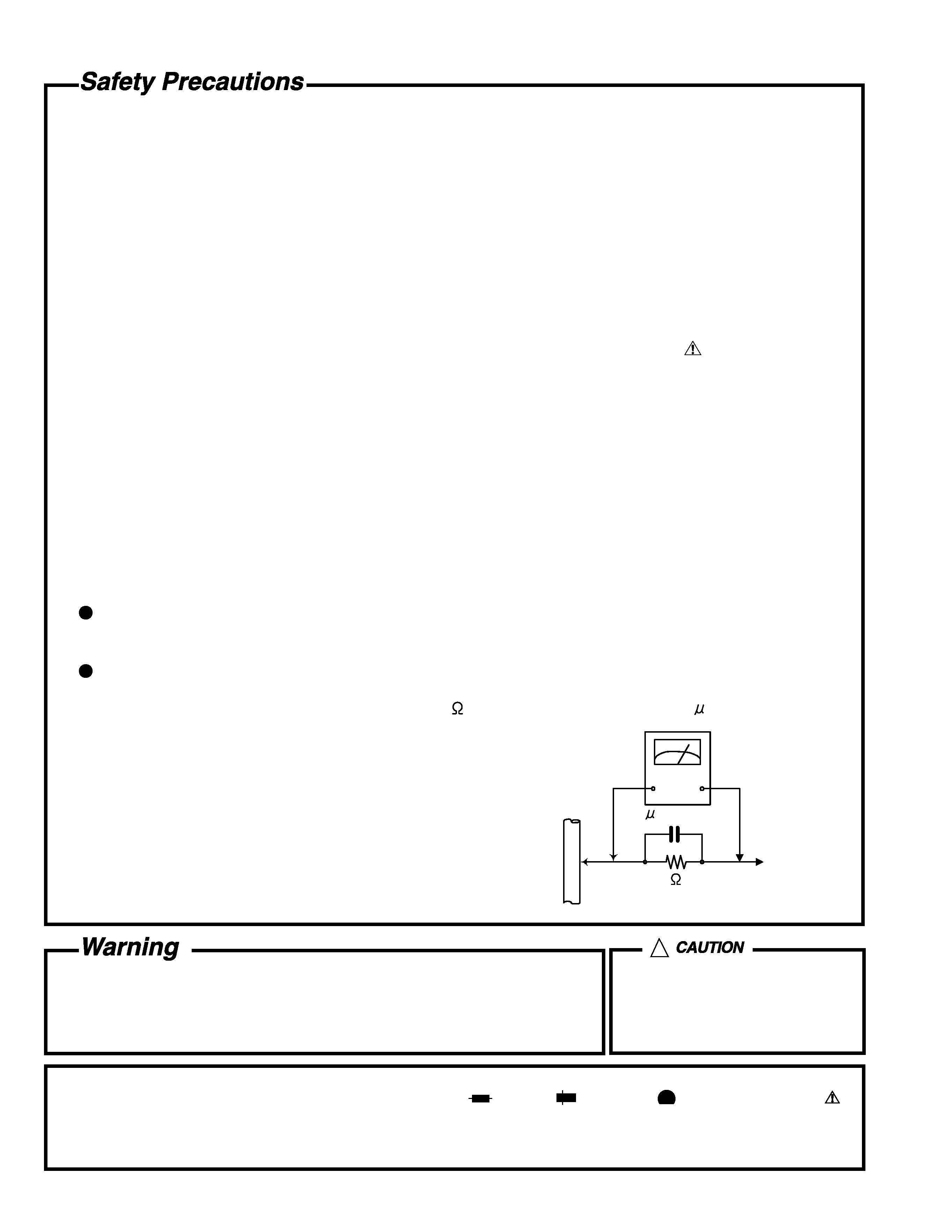
Alternate check method
Plug the AC line cord directly into the AC outlet. Use an AC voltmeter having, 1,000 ohms per volt or more
sensitivity in the following manner. Connect a 1,500
10W resistor paralleled by a 0.15 F AC-type capacitor
between an exposed metal part and a known good earth ground.
Measure the AC voltage across the resistor with the AC
voltmeter.
Move the resistor connection to each exposed metal part,
particularly any exposed metal part having a return path to
the chassis, and measure the AC voltage across the resistor.
Now, reverse plug in the AC outlet and repeat each
measurement. Voltage measured any must not exceed 0.75 V
AC (r.m.s.). This corresponds to 0.5 mA AC (r.m.s.).
1. This equipment has been designed and manufactured to meet international safety standards.
2. It is the legal responsibility of the repairer to ensure that these safety standards are maintained.
3. Repairs must be made in accordance with the relevant safety standards.
4. It is essential that safety critical components are replaced by approved parts.
5. If mains voltage selector is provided, check setting for local voltage.
Good earth ground
Place this
probe on
each exposed
metal part.
AC VOLTMETER
(Having 1000
ohms/volts,
or more sensitivity)
1500
10W
0.15 F AC TYPE
!
Burrs formed during molding may
be left over on some parts of the
chassis. Therefore, pay attention to
such burrs in the case of
preforming repair of this system.
In regard with component parts appearing on the silk-screen printed side (parts side) of the PWB diagrams, the
parts that are printed over with black such as the resistor (
), diode (
) and ICP (
) or identified by the " "
mark nearby are critical for safety.
(This regulation does not correspond to J and C version.)
RX-DV5SL
1-3
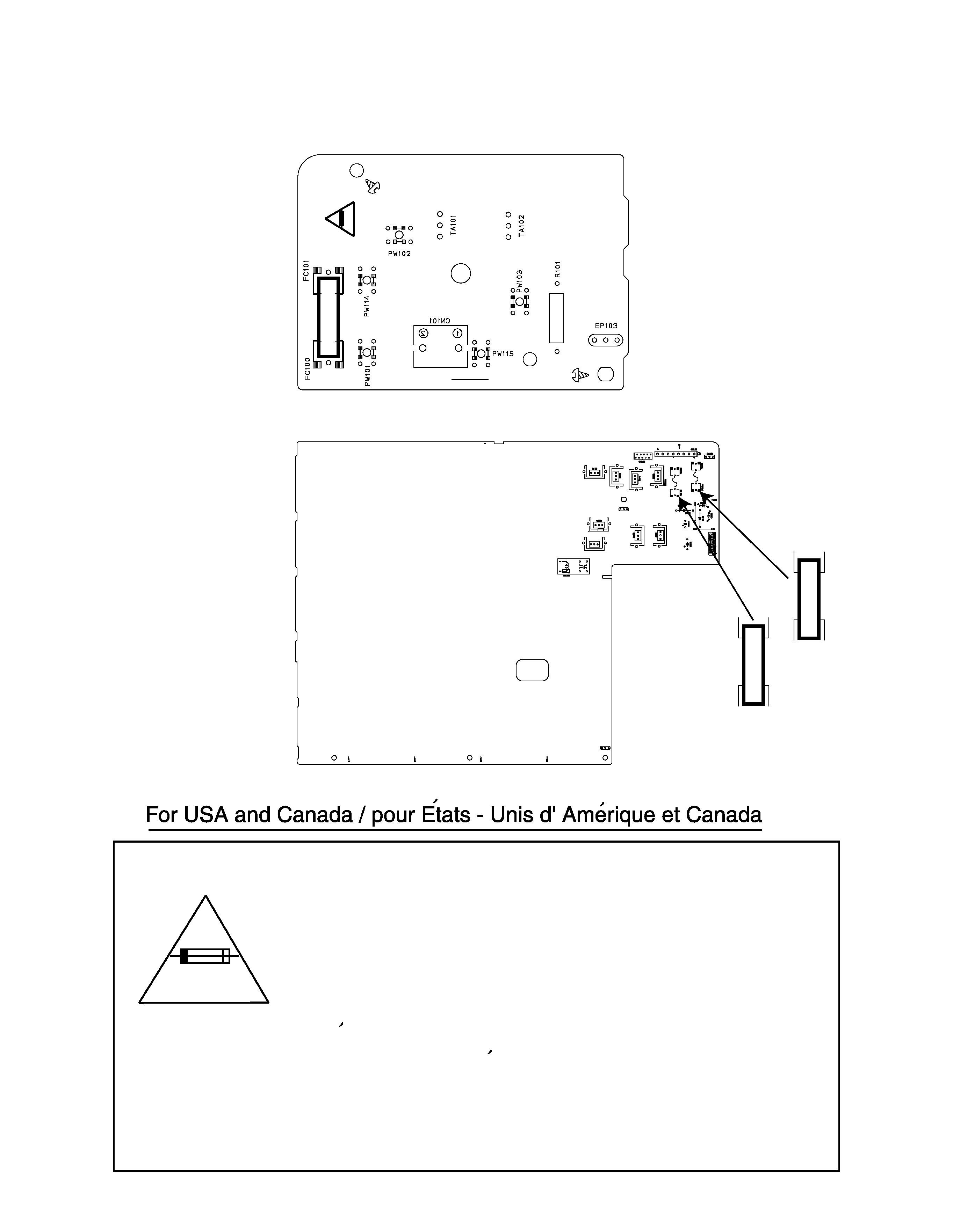
Caution: For continued protection against risk of
fire, replace only with same type 5A/125V for
F101, 2A/125V for F131 and F132.
This symbol specifies type of fast operating fuse.
Precaution: Pour eviter risques de feux, remplacez
le fusible de surete de F101 comme le meme type
que 5A/125V, et 2A/125V pour F131 et F132.
Ce sont des fusibles suretes qui functionnes rapide.
^
Importance administering point on the safety
Secondary parts
Primary part
LVA10332-A2
LVA10330-1
5A-125V
F
101
5A-125V
2A-125V
F
131
2A-125V
F
132
RX-DV5SL
1-4
Preventing static electricity
1. Grounding to prevent damage by static electricity
Electrostatic discharge (ESD), which occurs when static electricity stored in the body, fabric, etc. is discharged,
can destroy the laser diode in the traverse unit (optical pickup). Take care to prevent this when performing repairs.
2. About the earth processing for the destruction prevention by static electricity
In the equipment which uses optical pick-up (laser diode), optical pick-up is destroyed by the static electricity of
the work environment.
Be careful to use proper grounding in the area where repairs are being performed.
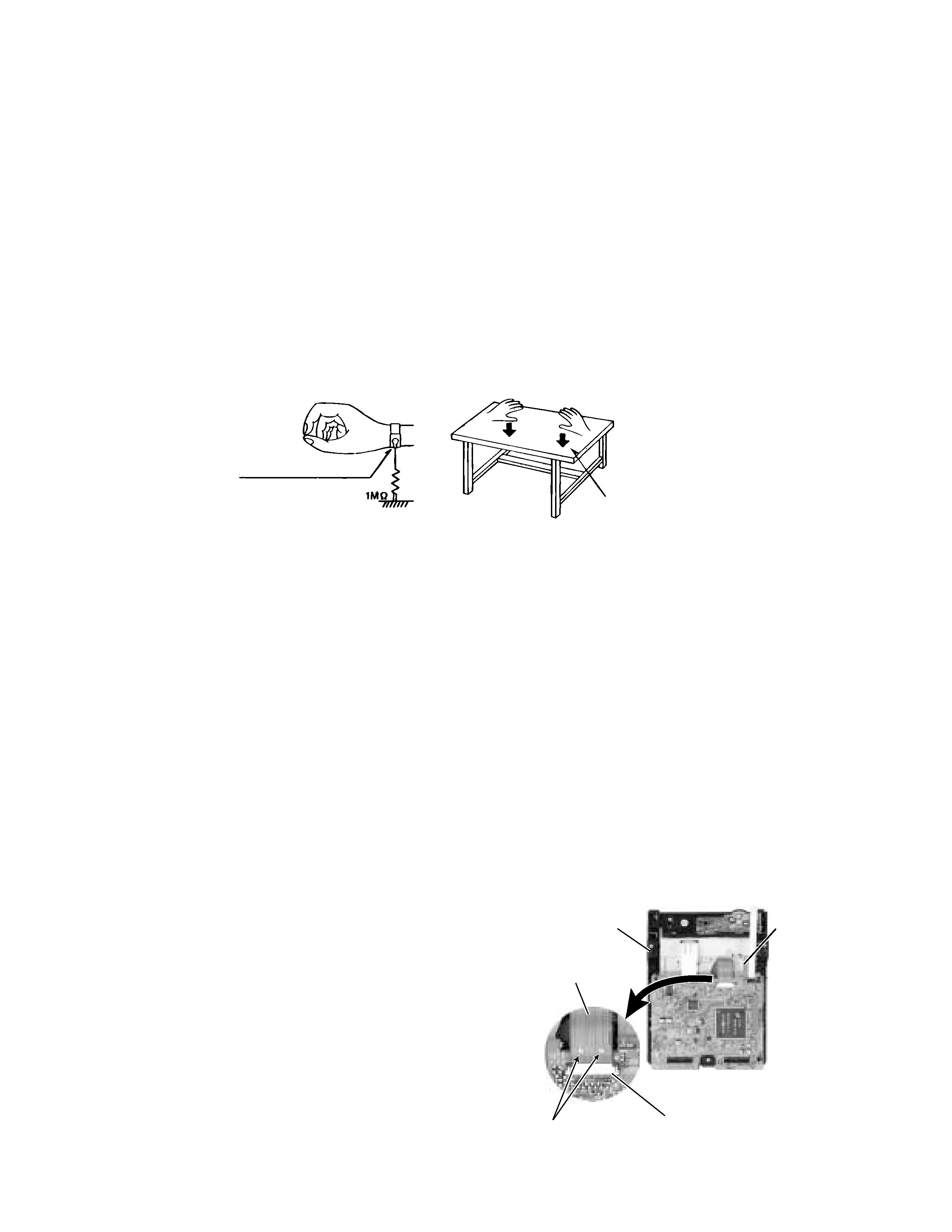
2-1 Ground the workbench
Ground the workbench by laying conductive material (such as a conductive sheet) or an iron plate over
it before placing the traverse unit (optical pickup) on it.
2-2 Ground yourself
Use an anti-static wrist strap to release any static electricity built up in your body.
3. Handling the optical pickup
1. In order to maintain quality during transport and before installation, both sides of the laser diode on the
replacement optical pickup are shorted. After replacement, return the shorted parts to their original condition.
(Refer to the text.)
2. Do not use a tester to check the condition of the laser diode in the optical pickup. The tester's internal power
source can easily destroy the laser diode.
4. Handling the traverse unit (optical pickup)
1. Do not subject the traverse unit (optical pickup) to strong shocks, as it is a sensitive, complex unit.
2. Cut off the shorted part of the flexible cable using nippers, etc. after replacing the optical pickup. For specific
details, refer to the replacement procedure in the text. Remove the anti-static pin when replacing the traverse
unit. Be careful not to take too long a time when attaching it to the connector.
3. Handle the flexible cable carefully as it may break when subjected to strong force.
4. It is not possible to adjust the semi-fixed resistor that adjusts the laser power. Do not turn it.
Conductive material
(conductive sheet) or iron plate
(caption)
Anti-static wrist strap
Attention when traverse unit is decomposed
Because the DVD/ CD mechanism assembly of this model is a
unit component, the individual component parts consisting of
the DVD / CD mechanism assembly are not supplied
separately.
If you need to decompose the traverse unit, solder the two
soldering points on the flexible board respectively before
removing traverse unit.
DVD / CD
holder
mechanism
DVD / CD unit
Pickup unit
connector
Soldering
points
Card wire
Fig.1
Fig.2
RX-DV5SL
1-5
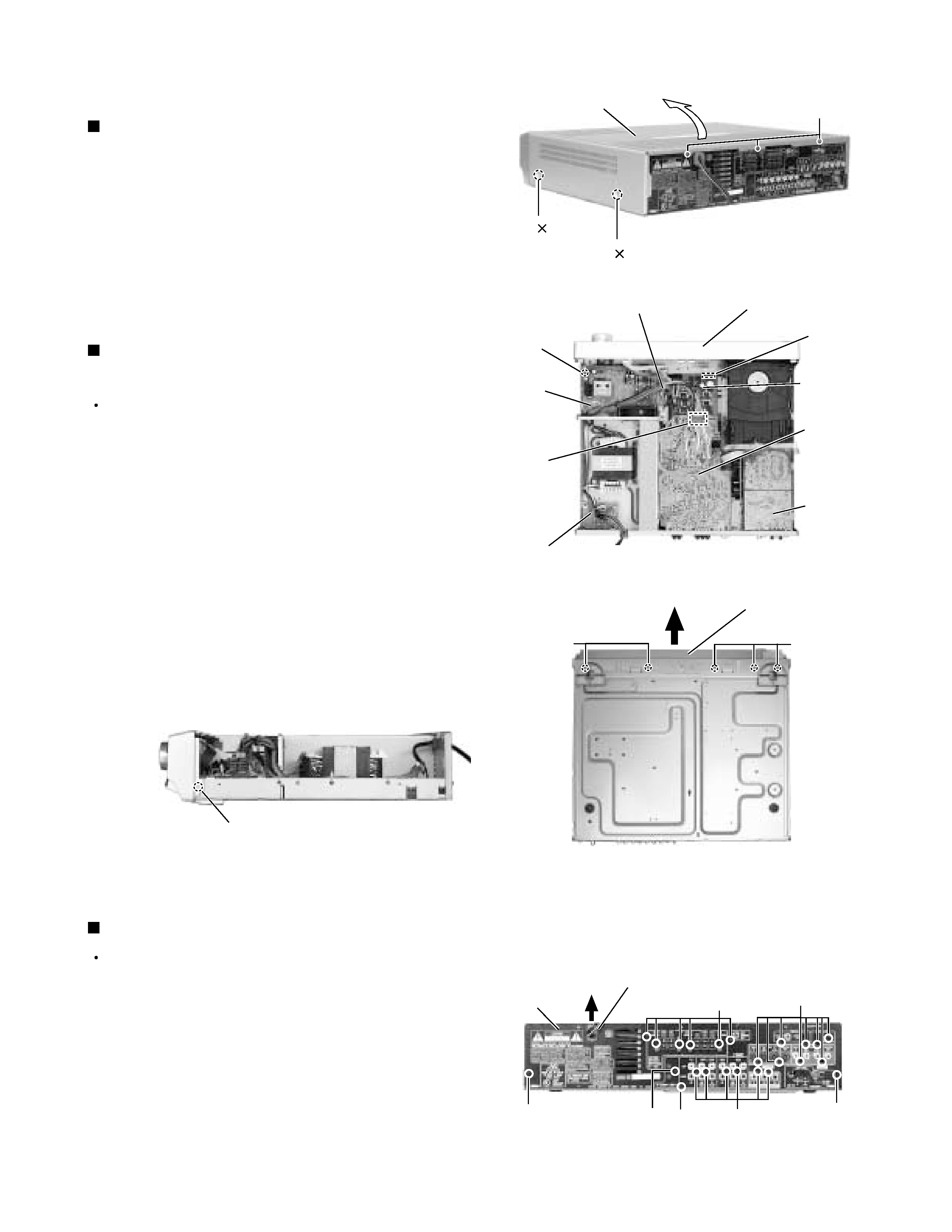
Remove the four screws marked A attaching the top
cover on both sides of the body.
Remove the three screws marked B on the back of
the body.
Remove the top cover from behind in the direction of
the arrow while pulling both sides outward.
1.
2.
3.
Disassembly method
Removing the top cover
(See Fig.1)
Prior to performing the following procedures, remove
the top cover.
Remove the power cord stopper from the rear panel
by moving it in the direction of the arrow.
Remove the twenty one screws marked E attaching
each boards to the rear panel on the back of the
body.
Remove the three screws marked F attaching the
rear panel on the back of the body.
1.
2.
3.
Removing the rear panel
(See Fig.5)
Prior to performing the following procedures, remove
the top cover.
Disconnect the card wire from the connector CN114
on the main board.
Remove the screw marked C attaching the earth
wire to the power supply board.
Remove the five screws marked D attaching the front
panel assembly on the bottom of the body. Detach
the front panel assembly toward the front.
Release the two joints marked a on both sides of the
body using a screwdriver.
1.
2.
3.
4.
Removing the front panel assembly
(See Fig.2 to 4)
Fig.1
Fig.2
Fig.3
Fig.4
A 2
A 2
B
Top cover
C
Power
supply
board
DSP
board
Main
board
Tie band
E
F
Power cord stopper
D
Front panel assembly
Front panel assembly
E
Rear panel
CN114
F
F
Amplifier
board
Power
/Fuse
board
CN201
Joint a
Fig.5
E
E
D