LVT1556-001A
[J]
RX-D205S / RX-D206B
AUDIO / VIDEO CONTROL RECEIVER
INSTRUCTIONS
For Customer Use:
Enter below the Model No. and Serial
No. which are located either on the rear,
bottom or side of the cabinet. Retain this
information for future reference.
Model No.
Serial No.
cover_RX-D205S206B[J]f.p65
06.3.22, 13:56
3
G-1
Caution
STANDBY/ON button!
Disconnect the mains plug to shut the power off completely (the
standby lamp goes off). When installing the apparatus, ensure
that the plug is easily accessible. The
STANDBY/ON button
in any position does not disconnect the mains line.
· When the unit is on standby, the standby lamp lights red.
· When the unit is turned on, the standby lamp goes off.
The power can be remote controlled.
Attention--Touche
STANDBY/ON!
Déconnectez la fiche secteur pour mettre l'appareil
complètement hors tension (le témoin d'attente s'éteint). Lors
de l'installation de l'appareil, assurez-vous que la fiche soit
facilement accessible. La touche
STANDBY/ON dans
n'importe quelle position ne déconnecte pas l'appareil du
secteur.
· Quand l'appareil est en mode d'attente, le témoin d'attente
s'allume en rouge.
· Quand l'appareil est sous tension, le témoin d'attente
s'éteint.
L'alimentation ne peut pas être commandée à distance.
Warnings, Cautions, and Others
Mises en garde, précautions et indications diverses
CAUTION
To reduce the risk of electrical shocks, fire, etc.:
1.
Do not remove screws, covers or cabinet.
2.
Do not expose this appliance to rain or moisture.
ATTENTION
Afin d'éviter tout risque d'électrocution, d'incendie, etc.:
1.
Ne pas enlever les vis ni les panneaux et ne pas ouvrir le
coffret de l'appareil.
2.
Ne pas exposer l'appareil à la pluie ni à l'humidité.
WARNING: TO REDUCE THE RISK OF FIRE
OR ELECTRIC SHOCK, DO NOT EXPOSE
THIS APPLIANCE TO RAIN OR MOISTURE.
CAUTION:
TO REDUCE THE RISK OF ELECTRIC SHOCK,
DO NOT REMOVE COVER (OR BACK).
NO USER SERVICEABLE PARTS INSIDE.
REFER SERVICING TO QUALIFIED SERVICE PERSONNEL.
RISK OF ELECTRIC SHOCK
DO NOT OPEN
The lightning flash with arrowhead symbol,
within an equilateral triangle is intended to
alert the user to the presence of uninsulated
"dangerous voltage" within the product's
enclosure
that
may
be
of
sufficient
magnitude to constitute a risk of electric
shock to persons.
The exclamation point within an equilateral
triangle is intended to alert the user to the
presence
of
important
operating
and
maintenance (servicing) instructions in the
literature accompanying the appliance.
CAUTION
For U.S.A
This equipment has been tested and found to comply with the limits
for a Class B digital device, pursuant to part 15 of the FCC Rules.
These limits are designed to provide reasonable protection against
harmful interference in a residential installation.
This equipment generates, uses and can radiate radio frequency
energy and, if not installed and used in accordance with the
instructions,
may
cause
harmful
interference
to
radio
communications. However, there is no guarantee that interference
will not occur in a particular installation. If this equipment does cause
harmful interference to radio or television reception, which can be
determined by turning the equipment off and on, the user is
encouraged to try to correct the interference by one or more of the
following measures:
Reorient or relocate the receiving antenna.
Increase the separation between the equipment and receiver.
Connect the equipment into an outlet on a circuit different from that
to which the receiver is connected.
Consult the dealer or an experienced radio/TV technician for help.
Note to CATV system installer:
This reminder is provided to call the CATV system installer's
attention to Section 820-40 of the NEC which provides
guidelines for proper grounding and, in particular, specifies
that the cable ground shall be connected to the grounding
system of the building, as close to the point of cable entry as
practical.
[European Union Only]
[Union européenne seulement]
For Canada/pour Le Canada
THIS DIGITAL APPARATUS DOES NOT EXCEED THE
CLASS B LIMITS FOR RADIO NOISE EMISSIONS FROM
DIGITAL APPARATUS AS SET OUT IN THE
INTERFERENCE-CAUSING EQUIPMENT STANDARD
ENTITLED "DIGITAL APPARATUS," ICES-003 OF THE
DEPARTMENT OF COMMUNICATIONS.
CET APPAREIL NUMERIQUE RESPECTE LES LIMITES DE
BRUITS RADIOELECTRIQUES APPLICABLES AUX
APPAREILS NUMERIQUES DE CLASSE B PRESCRITES
DANS LA NORME SUR LE MATERIEL BROUILLEUR;
"APPAREILS NUMERIQUES", NMB-003 EDICTEE PAR LE
MINISTRE DES COMMUNICATIONS.
Declaration of Conformity:
Trade Name: JVC
Model Number: RX-D205S/RX-D206B
Responsible Party: JVC Americas Corp.
Address: 1700 Valley Road, Wayne New Jersey 07470
Telephone Number: 973-317-5000
This device complies with Part 15 of the FCC Rules. Operation
is subject to the following two conditions:
(1) This device may not cause harmful interference.
(2) This device must accept any interference received,
including interference that may cause undesired operation.
CAUTION
Changes or modifications not approved by JVC could void the
user's authority to operate the equipment.
ATTENTION
Des changements ou modifications non approuvés par JVC
pourront invalider l'autorité de l'utilisateur à opérer cet
appareil.
safety_RX-D205S206B[J]f.p65
06.3.22, 13:58
1

1
Table of Contents
Parts identification ................................................ 2
Getting started ...................................................... 4
Before Installation .................................................................. 4
Checking the supplied accessories ....................................... 4
Putting batteries in the remote control ................................... 4
Connecting the FM and AM antennas ................................... 5
Connecting the speakers ....................................................... 6
Connecting video components .............................................. 7
USB connection ................................................................... 10
Connecting the power cord .................................................. 11
Basic operations ................................................. 12
1Turn on the power ............................................................ 12
2 Select the source to play .................................................. 12
3 Adjust the volume ............................................................ 13
Turning off the sounds temporarily ...................................... 14
Changing the display brightness .......................................... 14
Turning off the power with the Sleep Timer ......................... 14
Basic settings ...................................................... 15
Setting the speaker information easily
--Quick Speaker Setup ................................................. 15
Basic setting items ............................................................... 16
Operating procedure ............................................................ 17
Setting the speakers ............................................................ 17
Activating the EX/ES/PLIIx setting--EX/ES/PLIIx ............... 18
Selecting the main or sub channel--DUAL MONO ............. 19
Setting bass sound .............................................................. 19
Using the Midnight mode--MIDNIGHT MODE .................... 20
Setting the digital input (DIGITAL IN) terminals
--DIGITAL IN 1/2/3 ........................................................ 20
Selecting the component video input mode
--DVD VIDEO IN/VCR VIDEO IN/DBS VIDEO IN ......... 20
Sound adjustments ............................................. 21
Basic adjustment items ........................................................ 21
Operating procedure ............................................................ 21
Adjusting the speaker output levels ..................................... 22
Adjusting the equalization patterns
--D EQ 63Hz/250Hz/1kHz/4kHz/16kHz ........................ 22
Adjusting the bass sounds ................................................... 23
Adjusting the sound parameters for the
Surround/DSP modes ................................................... 23
Tuner operations ................................................. 25
Tuning in to stations manually .............................................. 25
Using preset tuning .............................................................. 25
Selecting the FM reception mode ........................................ 26
Creating realistic sound fields ........................... 27
Reproducing theater ambience ........................................... 27
Introducing the Surround modes ......................................... 27
Introducing the DSP modes ................................................. 29
Using the Surround/DSP modes ......................................... 30
Activating the Surround/DSP modes ................................... 31
AV COMPU LINK remote control system .......... 32
Operating other JVC products ........................... 34
Operating other manufacturers' products ........ 36
Troubleshooting .................................................. 39
Specifications ...................................................... 40
01-05RX-D205S206B[J]f.p65
06.3.22, 13:49
1
2
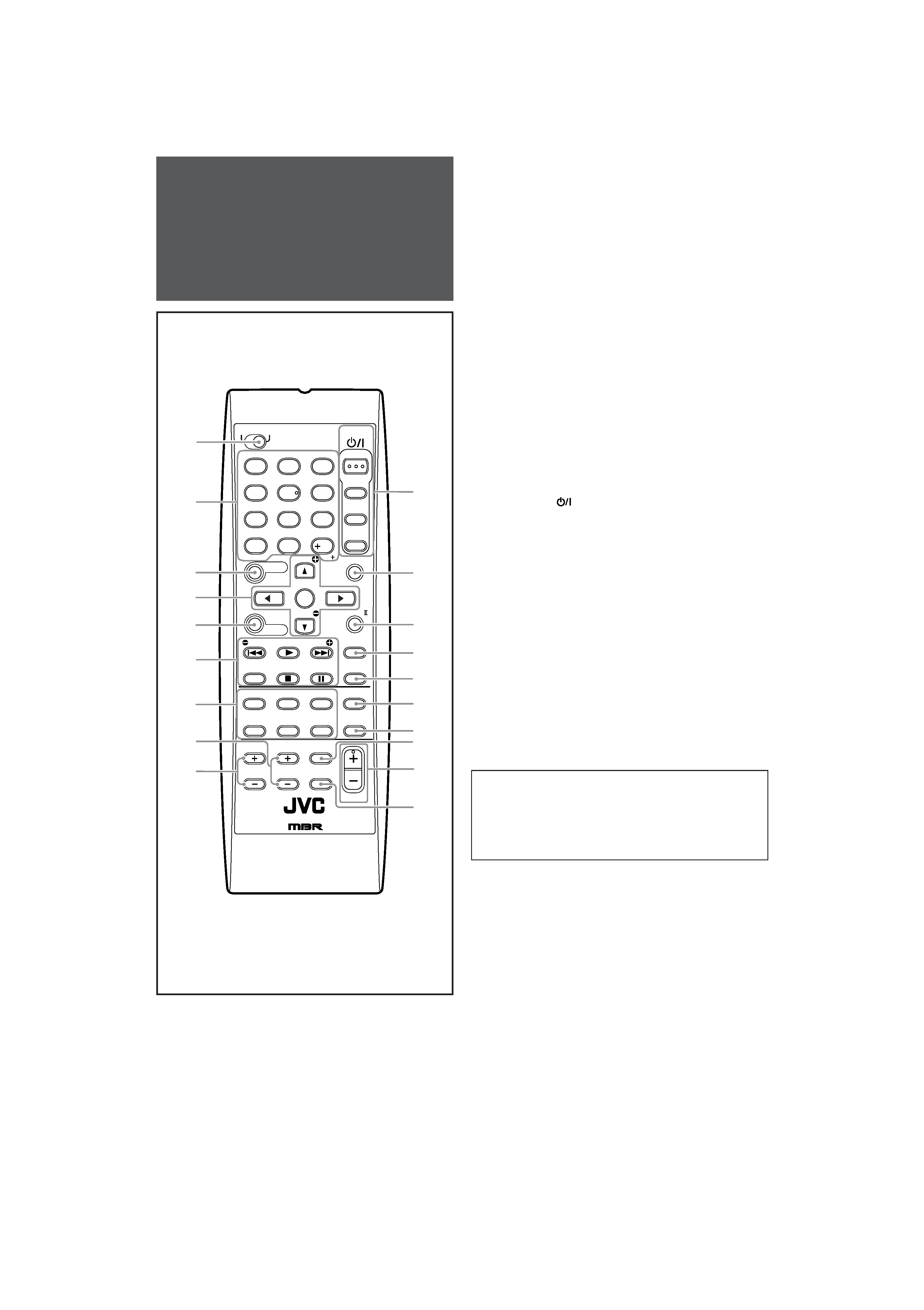
Remote control
See pages in parentheses for details.
1 DVR/DVD mode selector (35, 38)
2 · Numeric buttons (26, 34 38)
1 10, 0, +10, 100+
· Adjusting buttons for speaker and subwoofer output level
and sound adjustment (22)
TEST, FRONT L, FRONT R, EFFECT, CENTER,
SUBWFR, C. TONE, SURR L, SURR R, D. EQ FREQ, S
BACK L, S BACK R
· RETURN button (34)
3 SOUND button (22 24)
4 · Operating buttons for DVD recorder or DVD player*
cursor buttons (
3, 2, 5, ), ENTER (35, 38)
· Adjusting buttons for speakers and subwoofer output level
and D. EQ FREQ level (22)
LEVEL
9, LEVEL(
5
MENU button for DVD recorder or DVD player* (35, 38)
6 · Operating buttons for video components (34, 35, 37, 38)
4, 3, ¢, 7, 8, REW, FF, REC PAUSE
· Operating buttons for tuner (25, 26)
( TUNING, TUNING 9, MEMORY, FM MODE
7 Source selecting buttons (12, 25, 26, 34 38)
DVR/DVD, VCR, DBS, TV, USB, FM/AM
8 CHANNEL +/ buttons (34 38)
9 TV VOLUME +/ buttons (34, 36)
p STANDBY/ON
buttons (12, 34 38)
AUDIO, DVR/DVD, VCR, TV/DBS/CATV
q SURROUND button (31)
w EX/ES/PLIIx button (18)
e DIMMER button (14)
r SLEEP button (14)
t MIDNIGHT button (20)
y ANALOG/DIGITAL button (12)
u TV/VIDEO button (34, 36)
i VOLUME +/ button (13)
o MUTING button (14)
* These buttons can be used for operating a DVD recorder (JVC
product ONLY) or DVD player with the mode selector set to
"DVR" or "DVD" (see page 35).
If these buttons do not function normally, use the remote control
supplied with your DVD recorder or DVD player. Refer also to
the manuals supplied with the DVD recorder or DVD player for
details.
· When operating a DVD recorder (for JVC products
ONLY), set the mode selector (1) to "DVR."
· When operating a DVD player, set the mode selector (1)
to "DVD."
Parts identification
TV
A/V CONTROL
RECEIVER
AUDIO
DVR/DVD
VCR
TV/DBS/
CATV
TEST
EFFECT
C.TONE
*D.EQ FREQ
RETURN
SOUND
*FRONT L
EX/ES/PL x
REC PAUSE
MENU
DBS
DVR/DVD
FM/AM
USB
TV/VIDEO
SURROUND
MUTING
CHANNEL
VOLUME
MIDNIGHT
VCR
ANALOG/
DIGITAL
100
DVR
DVD
1
4
7
10
2
5
8
0
3
6
9
10
REMOTE CONTROL RM - SRX
D201J
2
p
w
e
r
1
q
TV VOLUME
STANDBY/ON
7
8
9
4
t
u
y
i
6
5
3
*FRONT R
*CENTER *SUBWFR
*SURR L
*SURR R
*S BACK L *S BACK R
ENTER
*LEVEL
*LEVEL
TUNING/REW
MEMORY
FF/TUNING
FM MODE
DIMMER
SLEEP
o
01-05RX-D205S206B[J]f.p65
06.3.22, 13:49
2
3
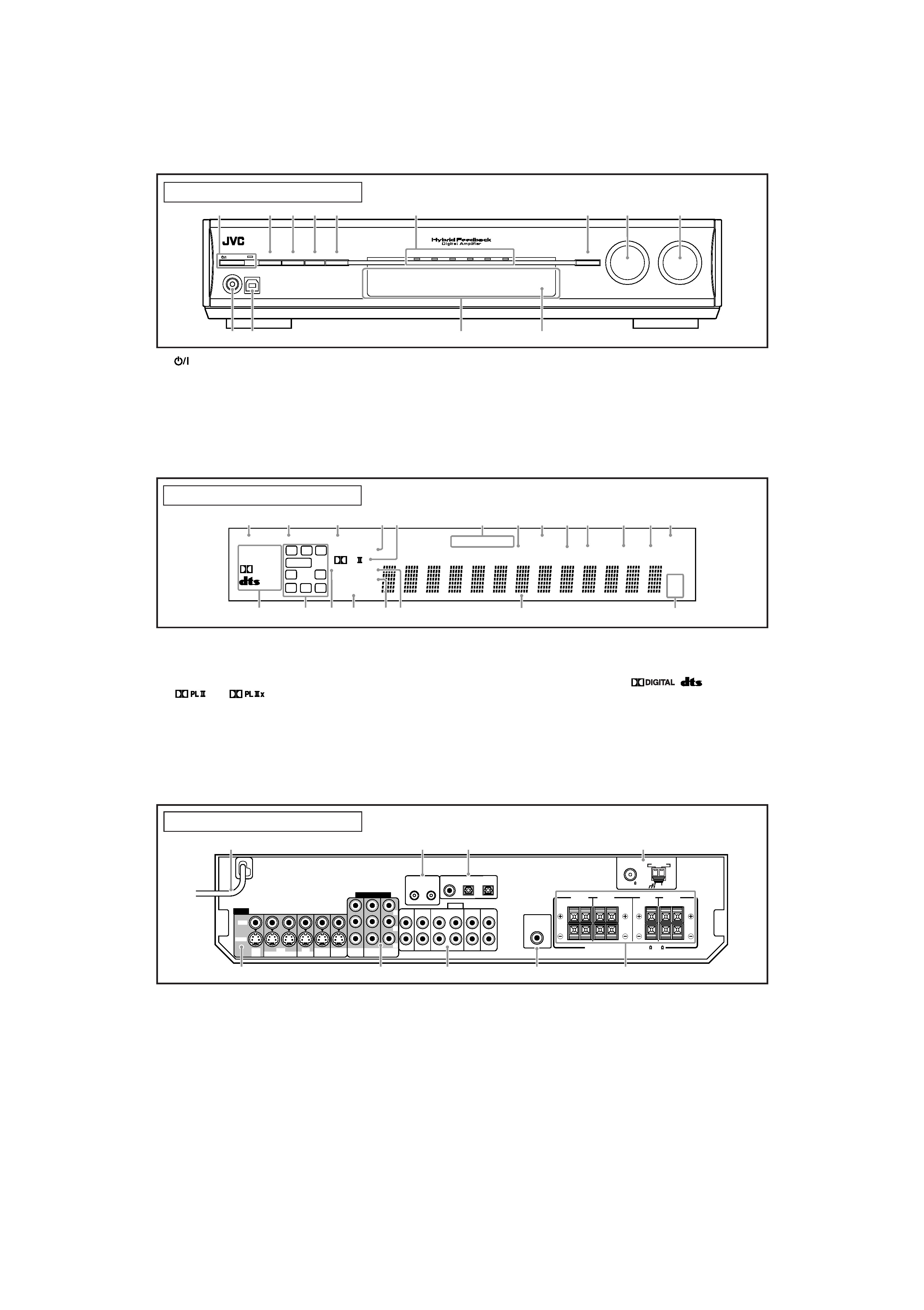
Front panel
1
STANDBY/ON button and standby lamp (12)
2 DIMMER button (14)
3 SETTING button (15, 17)
4 ADJUST button (21)
5 SURROUND button (31)
6 Source lamps
DVR/DVD, VCR, DBS, TV, USB, FM/AM
7 · SET button (15, 17, 21)
· TUNER PRESET button (26)
8 · SOURCE SELECTOR (12, 26)
· MULTI JOG (15, 17, 21, 26, 31)
9 MASTER VOLUME control (13)
p PHONES jack (13)
q USB terminal (10)
w Display window (see below)
e Remote sensor (4)
Display window
1 ANALOG indicator (13)
2 DUAL MONO indicator (19)
3 AUTO SURR (surround) indicator (31)
4 HEADPHONE indicator (13, 28)
5
and
indicator (27 29)
6 Tuner operation indicators (25)
TUNED, STEREO
7 DIGITAL EQ indicator (22)
8 AUTO MUTING indicator (26)
9 C.TONE indicator (24)
0 B.BOOST indicator (23)
- MIDNIGHT indicator (20)
1 Power cord (11)
2 AV COMPU LINK-III terminals (32)
3 DIGITAL IN terminals (10)
· Coaxial: 1(DVR/DVD)
· Optical: 2(DBS)
· Optical: 3(VCR)
4 ANTENNA terminals (5)
5 VIDEO jacks (7 9)
VIDEO (composite video) jacks, S-VIDEO jacks
· Input: DBS IN, VCR IN (PLAY), DVR/DVD IN (PLAY)
· Output: VCR OUT (REC), DVR OUT (REC), MONITOR OUT
Rear panel
See pages in parentheses for details.
= INPUT ATT (attenuate) indicator (23)
~ SLEEP indicator (14)
! Digital signal format indicators (13, 27, 28)
DIGITAL AUTO, LINEAR PCM,
,
, 96/24
@ Signal and speaker indicators (14)
# NEO:6 indicator (28)
$ VIRTUAL SB indicator (30)
% 3D-PHONIC indicator (28, 29)
^ DSP indicator (28, 29)
& Main display
* Frequency unit indicators
MHz (for FM stations), kHz (for AM stations)
6 COMPONENT VIDEO (Y, PB, PR) jacks (7 9)
VCR (DBS) IN, DVR/DVD IN, MONITOR OUT
7 AUDIO jacks (7 9)
· Input: TV IN, DBS IN, VCR IN (PLAY), DVR/DVD IN (PLAY)
· Output: VCR OUT (REC), DVR OUT (REC)
8 SUBWOOFER OUT jack (6)
9 Speakers terminals (6)
SURROUND BACK SPEAKERS, SURROUND SPEAKERS,
CENTER SPEAKER, FRONT SPEAKERS
AUDIO/VIDEO CONTROL RECEIVER
STANDBY/ON
DIMMER
SETTING
ADJUST
SURROUND
SOURCE
SELECTOR
/ MULTI JOG
MASTER
VOLUME
SET / TUNER PRESET
PHONES
USB
DVR/DVD
VCR
DBS
TV
USB
FM/AM
q
p
w
45
6
3
2
1
7
89
e
DIGITAL EQ
LINEAR PCM
L
LS
SB
RS
S.WFR
PL
NEO : 6 DSP
3D-PHONIC
LFE
CR
96 / 24
AUTO SURR
C.TONE
VIRTUAL SB
B.BOOST
TUNED
STEREO
SLEEP
AUTO MUTING
INPUT ATT
HEADPHONE
MHz
kHz
x
MIDNIGHT
DIGITAL
DIGITAL AUTO
ANALOG
DUAL MONO
SB
S
SB
1
23
@
~
4
6
=
*
89 0
-
5
7
&
$
#
%^
!
CAUTION:SPEAKER IMPEDANCE 6 -16
AV
COMPU LINK-
III
Y
PB
PR
COMPONENT VIDEO
VIDEO
AUDIO
MONITOR
OUT
DVR/DVD
IN
TV
IN
DBS
IN
OUT(REC)
IN(PLAY)
VCR
DVR
OUT(REC)
DVR/DVD
IN(PLAY)
VCR(DBS)
IN
MONITOR
OUT
DVR
OUT(REC)
VCR
OUT(REC)
IN(PLAY)
DBS
IN
DVR/DVD
IN(PLAY)
VIDEO
S-VIDEO
L
R
SURROUND BACK
SPEAKERS
SURROUND
SPEAKERS
CENTER
SPEAKER
FRONT
SPEAKERS
LEFT
RIGHT
LEFT
RIGHT
LEFT
RIGHT
ANTENNA
AM LOOP
AM EXT
COAXIAL
FM 75
SUBWOOFER
OUT
DIGITAL IN
2(DBS)
1(DVR/DVD)
3(VCR)
3
2
1
4
5
6
7
8
9
01-05RX-D205S206B[J]f.p65
06.3.22, 13:49
3