For Customer Use:
Enter below the Model No. and Serial
No. which are located either on the rear,
bottom or side of the cabinet. Retain this
information for future reference.
Model No.
Serial No.
LVT0618-002A
[C]
RX-8010VBK
+
-
+
-
+
-
23
1
56
4
89
7/P
0
+10
10
LINEDIF.ECT BOOST
EFFECT
MENU
ENTER
SIZE
ROOM
BASS
MODE
TEST
CTRTONE LIVENESS
MIDNIGHT
SOUND
SUBWFR
DIGITALEQ REARL REARR
L/RBAL CENTER
MUTING
CH/
LEVEL TVVOL
PLAY
STOP
/REW
DOWN TUNING UP
FF/
EXIT
BALL
BALR
VOLUME
CATV/DBS
CONTROL
TV/VIDEO
MENU
TEXT
REC
DISPLAY
PAUSE
PAUSE
SET
RETURN
FMMODE
100+
CONTROL
A/V CONTROL RECEIVER
RM-SRX8010J
CATV/DBS
VCR 1
TV
AUDIO
DSP
MODE
INPUT
ON/OFF
DVD MUILTI
DVD
USB
CD
CDR
TAPE/MD
TV/DBS
VIDEO
PHONO
FM/AM
VCR 1
VCR 2
SURROUND
ANALOG/DIGITAL SLEEP
POWER
POWER
POWER
POWER
CONTROL
DOWN
UP
EFFECT SETTING
DIGITAL
EQ
TV SOUND/DBS
VIDEO
VCR 2
VCR 1
DVD
DVD MULTI
MIDNIGHT MODE
DSP MODE
S-VIDEO
VIDEO
VIDEO
L--AUDIO--R
SURROUND ON/OFF
SUBWOOFER OUT ON/OFF
SPEAKERS ON/OFF
FM/AM TUNING
FM/AM PRESET
FM MODE
MEMORY
PHONES
1
STANDBY
POWER
USB AUDIO
INPUT
ANALOG/DIGITAL
INPUT ATT
FM / AM
USB AUDIO
TAPE / MD
CDR
CD
PHONO
LEVEL
ADJUST
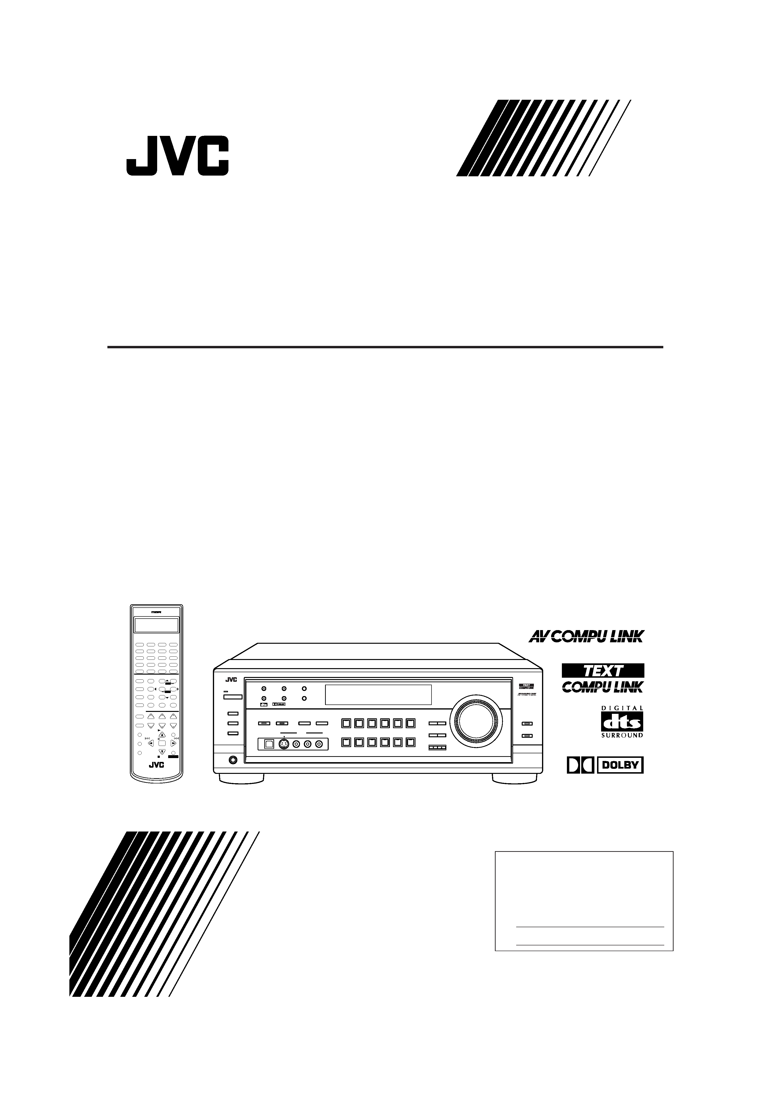
RX-8010V
AUDIO/VIDEO CONTROL RECEIVER
LINE DIRECT
BASS BOOST
MASTER VOLUME
DIGITAL
SURROUND
DIGITAL
2
SOUCE NAME
SOUCE NAME
DIGITAL
INSTRUCTIONS
MANUAL D'INSTRUCTIONS
AUDIO/VIDEO CONTROL RECEIVER
RECEPTEUR DE CONTROL AUDIO/VIDEO
RX-8010V[C]COVER_f
01.4.9, 2:02 PM
1
G-1
Warnings, Cautions and Others/
Mises en garde, précautions et indications diverses
CAUTION:
TO REDUCE THE RISK OF ELECTRIC SHOCK.
DO NOT REMOVE COVER (OR BACK)
NO USER SERVICEABLE PARTS INSIDE.
REFER SERVICING TO QUALIFIED SERVICE PERSONNEL.
RISK OF ELECTRIC SHOCK
DO NOT OPEN
The lightning flash with arrowhead symbol,
within an equilateral triangle is intended to
alert the user to the presence of uninsulated
"dangerous voltage" within the product's
enclosure
that
may
be
of
sufficient
magnitude to constitute a risk of electric
shock to persons.
The exclamation point within an equilateral
triangle is intended to alert the user to the
presence
of
important
operating
and
maintenance (servicing) instructions in the
literature accompanying the appliance.
CAUTION
WARNING: TO REDUCE THE RISK OF FIRE
OR ELECTRIC SHOCK, DO NOT EXPOSE
THIS APPLIANCE TO RAIN OR MOISTURE.
CAUTION
To reduce the risk of electrical shocks, fire, etc.:
1.
Do not remove screws, covers or cabinet.
2.
Do not expose this appliance to rain or moisture.
ATTENTION
Afin d'éviter tout risque d'électrocution, d'incendie, etc.:
1.
Ne pas enlever les vis ni les panneaux et ne pas ouvrir le
coffret de l'appareil.
2.
Ne pas exposer l'appareil à la pluie ni à l'humidité.
Declaration of Conformity
Model Number:
Trade Name:
Responsible Party:
Address:
Telephone Number:
This device complies with Part 15 of FCC Rules. Operation is
subject to the following two conditions: (1) This device may not
cause harmful interference, and (2) this device must accept any
interference
received,
including
interference
that
may
cause
undesired operation.
RX-8010VBK
JVC
JVC Americas Corp.
1700 Valley Road, Wayne
New Jersey 07470
973-315-5000
Déclaration de conformité
Numéro de modèle:
RX-8010VBK
Nom de marque:
JVC
Personne responsable: US JVC CORP.
Adresse:
1700 Valley Road
Wayne, N.J. 07470
Numéro de téléphone: (973) 315-5000
Cet ensemble se conforme à la partie 15 des règles de la FCC
(Federal Communications Commission), Le fonctionnement est sujet
aux deux conditions suivantes:
(1) Cet appareil ne peut pas causer d'interférences nuisibles, et (2)
cet appareil doit accepter toute interférence reçue, comprenant
des interférences qui peuvent causer un mauvais fonctionnement.
Note to CATV system installer:
This reminder is provided to call the CATV system installer's
attention to Section 820-40 of the NEC which provides
guidelines for proper grounding and, in particular, specifies
that the cable ground shall be connected to the grounding
system of the building, as close to the point of cable entry as
practical.
Caution POWER switch!
Disconnect the mains plug to shut the power off completely. The
POWER switch in any position does not disconnect the mains
line. The power can be remote controlled.
Attention Commutateur POWER!
Déconnecter la fiche de secteur pour couper complètement le
courant. Le commutateur POWER ne coupe jamais
complètement la ligne de secteur, quelle que soit sa position. Le
courant peut être télécommandé.
Caution SPEAKER LOAD SELECTOR switch!
Match the position of SPEAKER LOAD SELECTOR switch on
the back panel to the impedance of the speaker connected, to
protect from overheating.
RX-8010V[C]Safety_f
01.4.3, 10:25 AM
1
G-2
For Canada/pour Le Canada
THIS DIGITAL APPARATUS DOES NOT EXCEED THE CLASS
B LIMITS FOR RADIO NOISE EMISSIONS FROM DIGITAL
APPARATUS AS SET OUT IN THE INTERFERENCE-CAUSING
EQUIPMENT STANDARD ENTITLED "DIGITAL APPARATUS,"
ICES-003 OF THE DEPARTMENT OF COMMUNICATIONS.
CET APPAREIL NUMERIQUE RESPECTE LES LIMITES DE
BRUITS RADIOELECTRIQUES APPLICABLES AUX APPAREILS
NUMERIQUES DE CLASSE B PRESCRITES DANS LA NORME
SUR LE MATERIEL BROUILLEUR; "APPAREILS
NUMERIQUES", NMB-003 EDICTEE PAR LE MINISTRE DES
COMMUNICATIONS.
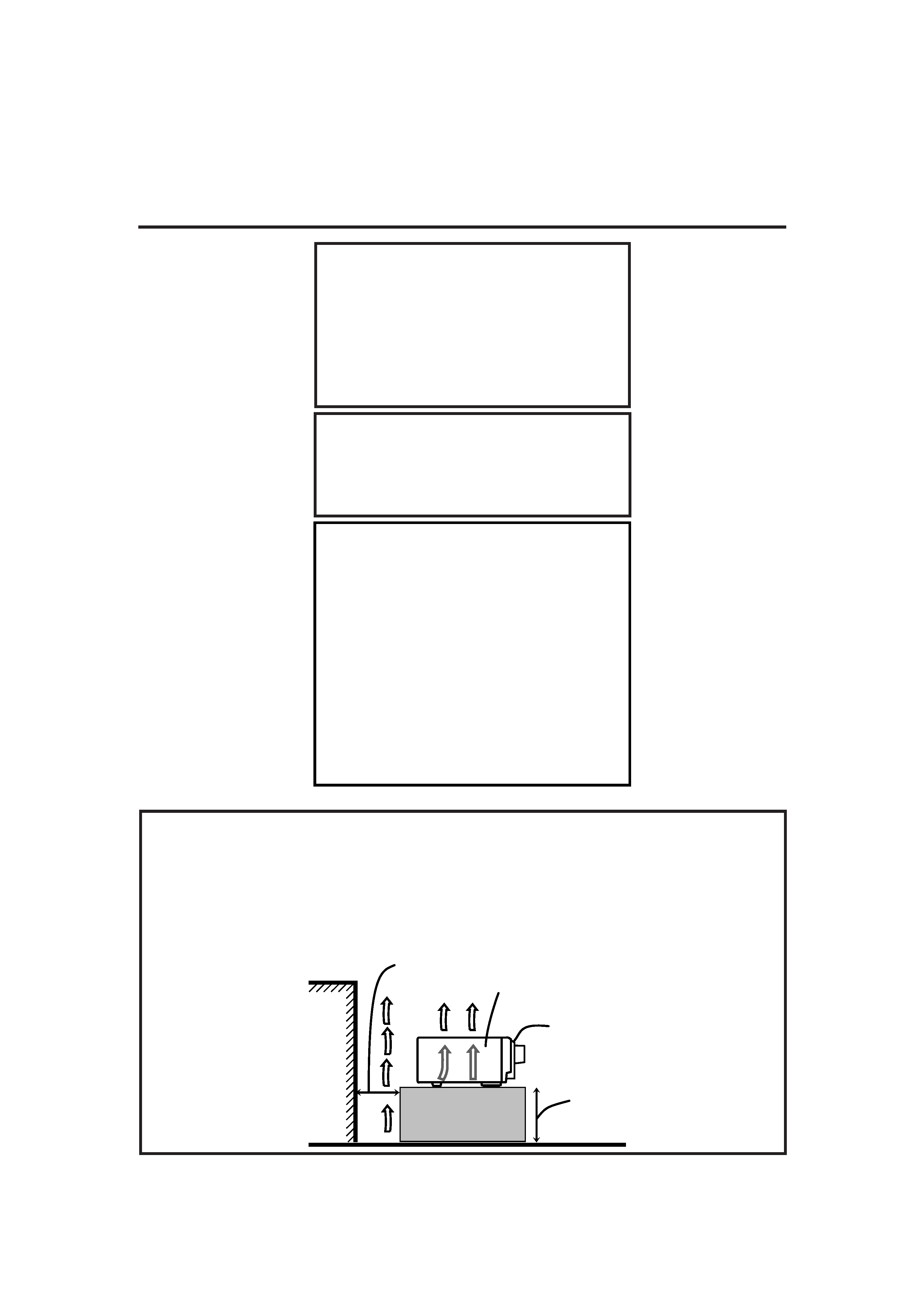
Caution: Proper Ventilation
To avoide risk of electric shock and fire and to protect from dam-
age.
Locate the apparatus as follows:
Front:
No obstructions open spacing.
Sides:
No obstructions in 10 cm from the sides.
Top:
No obstructions in 10 cm from the top.
Back:
No obstructions in 15 cm from the back
Bottom:
No obstructions, place on the level surface.
In addition, maintain the best possible air circulation as illustrated.
Attention: Ventilation Correcte
Pour éviter les chocs électriques, l'incendie et tout autre dégât.
Disposer l'appareil en tenant compte des impératifs suivants
Avant:
Rien ne doit gêner le dégagement
Flancs:
Laisser 10 cm de dégagement latéral
Dessus:
Laisser 10 cm de dégagement supérieur
Arrière:
Laisser 15 cm de dégagement arrière
Dessous:
Rien ne doit obstruer par dessous; poser l'appareil
sur une surface plate.
Veiller également à ce que l'air circule le mieux possible comme
illustré.
This equipment has been tested and found to comply with the limits
for a Class B digital device, pursuant to part 15 of the FCC Rules.
These limits are designed to provide reasonable protection against
harmful interference in a residential installation.
This equipment generates, uses and can radiate radio frequency
energy and, if not installed and used in accordance with the
instructions,
may
cause
harmful
interference
to
radio
communications. However, there is no guarantee that interference
will not occur in a particular installation. If this equipment does cause
harmful interference to radio or television reception, which can be
determined by turning the equipment off and on, the user is
encouraged to try to correct the interference by one or more of the
following measures:
Reorient or relocate the receiving antenna.
Increase the separation between the equipment and receiver.
Connect the equipment into an outlet on a circuit different from that
to which the receiver is connected.
Consult the dealer or an experienced radio/TV technician for help.
Changes
or
modifications
not
expressly
approved
by
the
manufacturer for compliance could void the user's authority to
operate the equipment.
For Canada/pour le Canada
CAUTION: TO PREVENT ELECTRIC SHOCK, MATCH WIDE
BLADE OF PLUG TO WIDE SLOT, FULLY INSERT
ATTENTION: POUR EVITER LES CHOCS ELECTRIQUES,
INTRODUIRE LA LAME LA PLUS LARGE DE LA FICHE DANS LA
BORNE CORRESPONDANTE DE LA PRISE ET POUSSER
JUSQUAU FOND
Spacing 15 cm or more
Dégagement de 15 cm
ou plus
RX-8010VBK
Wall or obstructions
Mur, ou obstruction
Front
Avant
Stand height 15 cm or more
Hauteur du socle: 15 cm ou plus
Floor
Plancher
RX-8010V[C]Safety_f
01.4.3, 10:25 AM
2

1
English
Table of Contents
Creating a Surround Field in Your Room ....... 24
7 Surround modes .................................................................... 24
7 DSP modes ........................................................................... 24
Reproducing the Sound Field .................................................... 25
Available DSP Modes According to the Speaker Arrangement .. 26
Adjusting the Surround Modes ................................................ 27
Adjusting the DAP Modes ....................................................... 28
Adjusting the Surround Modes with the DAP Modes .............. 30
Adjusting the 5 CH/4 CH Stereo Mode ................................... 32
Adjusting the 3D-PHONIC Modes .......................................... 33
Using the DVD MULTI Playback Mode .......... 35
Activating the DVD MULTI Playback Mode .......................... 35
Using the On-Screen Menus ........................ 36
7 Showing the MENU on the TV Screen ................................ 36
7 Activating the Surround Modes ............................................ 36
7 Activating the DSP Modes ................................................... 36
7 Selecting the Analog or Digital Input Mode........................... 36
7 Adjusting the Equalization Pattern ....................................... 37
7 Adjusting the Surround and DSP Modes .............................. 37
7 Adjusting the DVD MULTI Playback Mode ........................ 38
7 Listening at Night -- Midnight Mode .................................. 38
7 Attenuating the Input Signal ................................................. 38
7 Selecting the Line Direct Function ....................................... 39
7 Selecting the Bass Boost Function ....................................... 39
7 Activating the Subwoofer Sound .......................................... 39
7 Operating the Tuner .............................................................. 39
7 Storing the Preset Stations .................................................... 39
7 Setting the Basic Setting Items ............................................. 40
COMPU LINK Remote Control System ......... 41
TEXT COMPU LINK Remote Control System .. 42
7 Showing the Disc Information on the TV Screen................. 43
7 Searching for a Disc (Only for the CD player) .................... 44
7 Entering the Disc Information .............................................. 45
AV COMPU LINK Remote Control System .... 47
Operating JVC's Audio/Video Components ... 49
Operating Audio Components .................................................. 49
Operating Video Components .................................................. 51
Operating Other Manufacturers' Video
Equipment ............................................ 52
Troubleshooting ......................................... 55
Specifications ............................................ 57
Parts Identification ...................................... 2
Getting Started ........................................... 3
Before Installation ...................................................................... 3
Checking the Supplied Accessories ........................................... 3
Connecting the FM and AM Antennas ....................................... 3
Connecting the Speakers ............................................................ 4
Connecting Audio/Video Components ....................................... 5
7 Analog Connections ............................................................... 5
7 Digital Connections ................................................................ 8
7 USB Connection ..................................................................... 9
Connecting the Power Cord ..................................................... 10
Putting Batteries in the Remote Control .................................. 10
Basic Operations ....................................... 11
Turning the Power On and Off (Standby) ................................ 11
Selecting the Source to Play ..................................................... 11
Adjusting the Volume ............................................................... 12
Selecting the Front Speakers .................................................... 13
Muting the Sound ..................................................................... 13
Listening at Night -- Midnight Mode ..................................... 13
Activating the Subwoofer Sound ............................................. 14
Reinforcing the Bass ................................................................ 14
Attenuating the Input Signal .................................................... 14
Selecting the Line Direct Function .......................................... 14
Adjusting the Equalization Patterns ......................................... 15
Using the Sleep Timer .............................................................. 15
Recording a Source .................................................................. 15
Basic Settings ........................................... 16
Adjusting the Front Speaker Output Balance ........................... 16
Changing the Source Name ...................................................... 16
Selecting the Video Input Terminal .......................................... 16
Setting the Subwoofer Information .......................................... 17
Adjusting the Subwoofer Output Level .................................... 17
Setting the Speakers for a Surround Field ................................ 17
Digital Input (DIGITAL IN) Terminal Setting ......................... 19
Selecting the Analog or Digital Input Mode ............................ 20
Showing the Text Information on the Display ......................... 21
Basic Setting and Adjustment -- Auto Memory ...................... 21
Receiving Radio Broadcasts ........................ 22
Tuning in Stations Manually .................................................... 22
Using Preset Tuning ................................................................. 22
Selecting the FM Reception Mode ........................................... 23
EN01_10.RX-8010V[C]_f
01.4.3, 9:56 AM
1
2
English
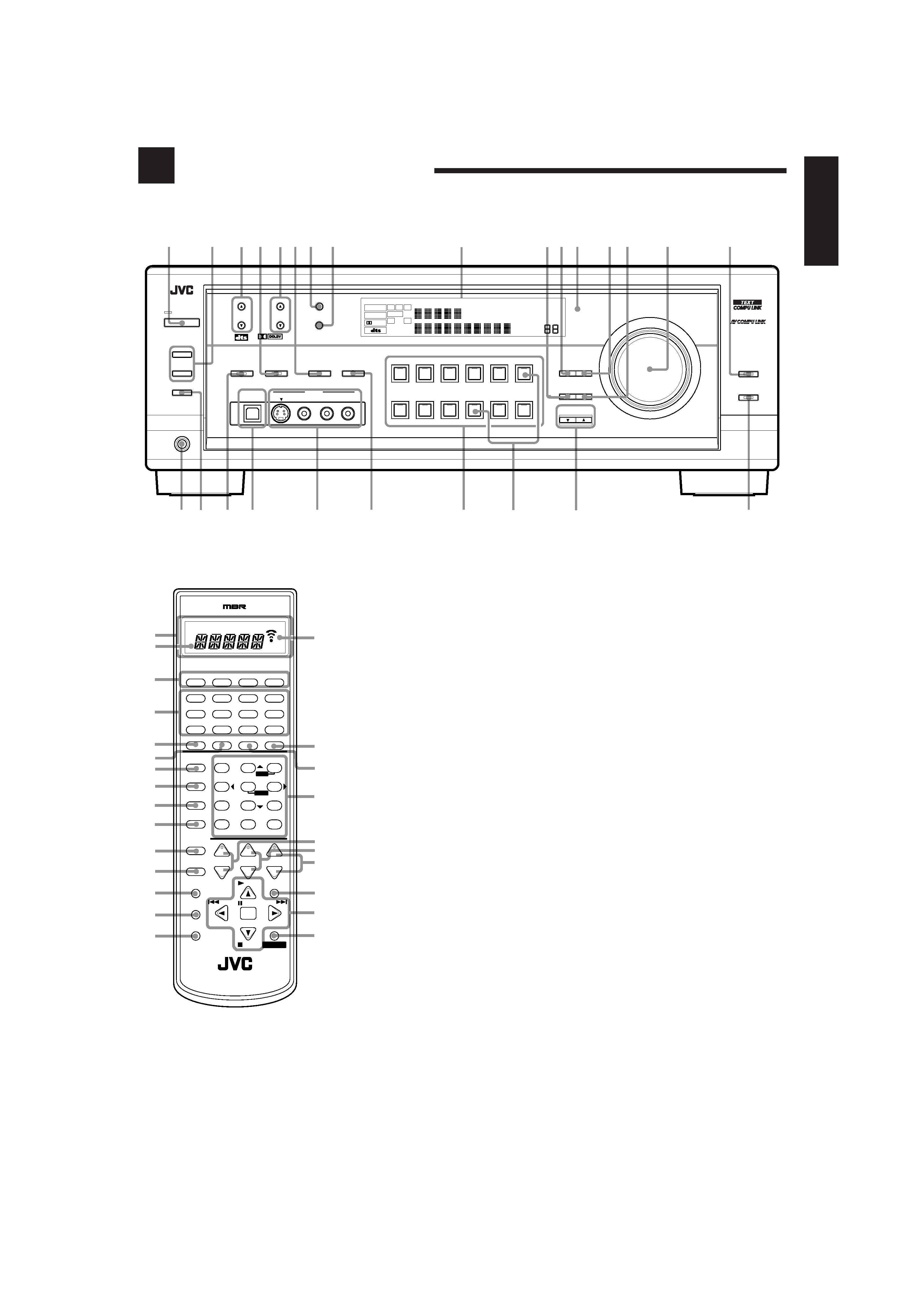
Parts Identification
Become familiar with the buttons and controls on the receiver before use.
Refer to the pages in parentheses for details.
CONTROL
+
-
+
-
+
-
23
1
56
4
89
7/P
0
+10
10
LINEDIF.ECT
BOOST
EFFECT
MENU
ENTER
SIZE
ROOM
BASS
MODE
TEST
CTRTONE
LIVENESS
MIDNIGHT
SOUND
SUBWFR
DIGITALEQ REARL REARR
L/RBAL CENTER
MUTING
CH/
LEVEL TVVOL
PLAY
STOP
/REW
DOWN TUNING UP
FF/
EXIT
BALL
BALR
VOLUME
CATV/DBS
CONTROL
TV/VIDEO
MENU
TEXT
REC
DISPLAY
PAUSE
PAUSE
SET
RETURN
FMMODE
100+
CONTROL
A/V CONTROL RECEIVER
RM-SRX8010J
CATV/DBS
VCR 1
TV
AUDIO
DSP
MODE
INPUT
ON/OFF
DVD MUILTI
DVD
USB
CD
CDR
TAPE/MD
TV/DBS
VIDEO
PHONO
FM/AM
VCR 1
VCR 2
SURROUND
ANALOG/DIGITAL SLEEP
POWER
POWER
POWER
POWER
7
8
9
&
^
%
$
#
@
!
=
-
1
4
3
)
*
(
2
b
a
5
6
0
~
Front Panel
1 POWER button and STANDBY lamp (11)
2 · SPEAKERS ON/OFF 1 button (13)
· SPEAKERS ON/OFF 2 button (13)
3 FM/AM TUNING
5/ buttons (22)
4 DSP MODE button and lamp (26)
5 FM/AM PRESET
5/ buttons (22, 23)
6 · INPUT ANALOG/DIGITAL button (20)
· INPUT ATT button (14)
7 FM MODE button (23)
8 MEMORY button (22)
9 Display (11)
p EFFECT button (28, 31 34)
q DIGITAL EQ button (15)
w Remote sensor (10)
e LEVEL ADJUST button (16, 17, 28 35)
r SETTING button (16 19, 21)
t MASTER VOLUME control (12)
y LINE DIRECT button and lamp (14)
u PHONES jack (13)
i SUBWOOFER OUT ON/OFF button (14)
o SURROUND ON/OFF button and lamp (26)
; USB AUDIO terminal (9)
a VIDEO input terminals (7)
s MIDNIGHT MODE button (13)
d Source selecting buttons and lamps (11)
DVD MULTI, DVD, VCR 1, VCR 2, VIDEO, TV
SOUND/DBS, PHONO, CD, CDR, TAPE/MD,
USB AUDIO, FM/AM
f SOURCE NAME buttons (16)
g CONTROL UP
5/DOWN buttons
h BASS BOOST button and lamp (14)
* These buttons function only after pressing
10 keys on the remote control which are
marked with an asterisk (*).
a
;
o
u
2
1
34 5
7 8
w
9q
y
is
d
6
h
PRO LOGIC
DGTL
ANALOG
AUTO
DVD
MULTI
DSP
HEADPHONE DIGITAL EQ
INPUT ATT
SLEEP VOLUME
ONETOUCH OPERATION
3DPHONIC MIDNIGHT MODE
AUTO MUTING TUNED STEREO
LINEAR PCM
DIGITAL
L
SUBWFR
LS
RS
C
R
S
SPEAKERS
12
LFE
pr
t
g
f
e
CONTROL
DOWN
UP
EFFECT SETTING
DIGITAL
EQ
TV SOUND/DBS
VIDEO
VCR 2
VCR 1
DVD
DVD MULTI
MIDNIGHT MODE
DSP MODE
S-VIDEO
VIDEO
VIDEO
L--AUDIO--R
SURROUND ON/OFF
SUBWOOFER OUT ON/OFF
SPEAKERS ON/OFF
FM/AM TUNING
FM/AM PRESET
FM MODE
MEMORY
2
PHONES
STANDBY
POWER
USB AUDIO
INPUT
ANALOG/DIGITAL
INPUT ATT
FM / AM
USB AUDIO
TAPE / MD
CDR
CD
PHONO
LEVEL
ADJUST
RX-8010V
AUDIO/VIDEO CONTROL RECEIVER
LINE DIRECT
BASS BOOST
MASTER VOLUME
DIGITAL
SURROUND
DIGITAL
1
SOURCE NAME
SOURCE NAME
Remote Control
1 Display window (11)
a. Remote control operation mode indicator
b. Signal transmission indicator
Lights up when transmitting the remote
control signal.
2 POWER buttons (11, 51 54)
CATV/DBS, VCR 1, TV, AUDIO
3 Source selecting buttons (11)
DVD,DVDMULTI,CD,FM/AM,TV/DBS,VIDEO,
CDR, PHONO, VCR 1,VCR 2, TAPE/MD, USB
4 SURROUND ON/OFF button (26)
5 DSP MODE button (26)
6 LINE DIRECT button (14)
7 MIDNIGHT MODE button (13)
8 SOUND button (14, 16, 27 35, 49)
9 MUTING button (13)
0 CATV/DBS CONTROL button (53)
- TV/VIDEO button (51, 52)
= MENU button (36 40)
~ TEXT DISPLAY button (43 46)
! REC PAUSE button (50, 51, 53)
@ SLEEP button (15)
# ANALOG/DIGITAL INPUT button (20)
$ · 10 keys for selecting preset channels (23)
· 10 keys for adjusting sound (14, 16, 27 35,
49)
· 10 keys for operating audio/video components
(49 54)
% · LEVEL +/ buttons* (15, 27 35)
· BAL L and BAL R buttons* (16)
· CH +/ buttons (51 53)
^ TV VOL +/ buttons (51, 52)
& VOLUME +/ buttons (12)
* EXIT button (36 40, 43 45)
( · TUNING UP
3/DOWN 2 buttons (22, 49)
· On screen operation buttons (36 40, 43 46)
· Operating buttons for audio/video components
(49 54)
) CONTROL button (50, 51)
EN01_10.RX-8010V[C]_f
01.4.3, 9:56 AM
2