SERVICE MANUAL
AUDIO/VIDEO CONTROL RECEIVER
No.20979
May. 2001
COPYRIGHT
2001 VICTOR COMPANY OF JAPAN, LTD.
RX-8010RBK
RX-8012RSL
RX-8010RBK/ RX-8012RSL
Area Suffix
Contents
Safety precautions --------------------------------------------------------1-2
Disassembly method -----------------------------------------------------1-3
Adjustment method -------------------------------------------------------1-9
Self-diagnose function ----------------------------------------------------1-10
Description of major ICs -------------------------------------------------1-12~29
E
EN
Continental Europe
Northern Europe
CONTROL
+
-
+
-
+
-
23
1
56
4
89
7/P
0
+10
10
LINEDIF.ECT
BOOST
EFFECT
MENU
ENTER
SIZE
ROOM
BASS
MODE
TEST
CTRTONE
LIVENESS
MIDNIGHT
SOUND
*SUBWFR
*DIGITALEQ *REARL *REARR
*L/R BAL *CENTER
MUTING
CH/
* LEVEL TV VOL
PLAY
STOP
/REW
FF/
EXIT
*BAL L
*BAL R
VOLUME
CATV/DBS
CONTROL
TV/VIDEO
MENU
TEXT
REC
DISPLAY
PAUSE
PAUSE
SET
RETURN
FMMODE
100+
CONTROL
A/V CONTROL RECEIVER
CATV/DBS
VCR 1
TV
AUDIO
DSP
MODE
INPUT
ON/OFF
DVD MUILTI
DVD
USB
CD
CDR
TAPE/MD
TV/DBS
VIDEO
PHONO
FM/AM
VCR 1
VCR 2
SURROUND
ANALOG/DIGITAL SLEEP
PTYPTY SEARCHPTY
DISPLAY
MODE
EON
TA / NEWS / INFO
DISPLAY MODE
PTY SEARCH
CONTROL
DOWN
UP
EFFECT SETTING
DIGITAL
EQ
TV SOUND/DBS
VIDEO
VCR 2
VCR 1
DVD
DVD MULTI
MIDNIGHT MODE
DSP MODE
S-VIDEO
VIDEO
VIDEO
L--AUDIO--R
SURROUND ON/OFF
SUBWOOFER OUT ON/OFF
SPEAKERS ON/OFF
FM/AMTUNING
FM/AM PRESET
FM MODE
MEMORY
PHONES
1
STANDBY
USB AUDIO
PUSH OPEN
INPUT
ANALOG/DIGITAL
INPUT ATT
FM / AM
USB AUDIO
TAPE / MD
CDR
CD
PHONO
LEVEL
ADJUST
AUDIO/VIDEO CONTROL RECEIVER
LINE DIRECT
BASS BOOST
MASTER VOLUME
DIGIT A L
SURR OUND
DIGIT A L
2
SOUCE NAME
SOUCE NAME
STANDBY/ON
DIGIT AL
RX-8010RBK/ RX-8012RSL
1-2
1. This design of this product contains special hardware and many circuits and components specially for safety
purposes. For continued protection, no changes should be made to the original design unless authorized in
writing by the manufacturer. Replacement parts must be identical to those used in the original circuits. Services
should be performed by qualified personnel only.
2. Alterations of the design or circuitry of the product should not be made. Any design alterations of the product
should not be made. Any design alterations or additions will void the manufacturer`s warranty and will further
relieve the manufacture of responsibility for personal injury or property damage resulting therefrom.
3. Many electrical and mechanical parts in the products have special safety-related characteristics. These
characteristics are often not evident from visual inspection nor can the protection afforded by them necessarily
be obtained by using replacement components rated for higher voltage, wattage, etc. Replacement parts which
have these special safety characteristics are identified in the Parts List of Service Manual. Electrical
components having such features are identified by shading on the schematics and by (
) on the Parts List in
the Service Manual. The use of a substitute replacement which does not have the same safety characteristics
as the recommended replacement parts shown in the Parts List of Service Manual may create shock, fire, or
other hazards.
4. The leads in the products are routed and dressed with ties, clamps, tubings, barriers and the like to be
separated from live parts, high temperature parts, moving parts and/or sharp edges for the prevention of
electric shock and fire hazard. When service is required, the original lead routing and dress should be
observed, and it should be confirmed that they have been returned to normal, after re-assembling.
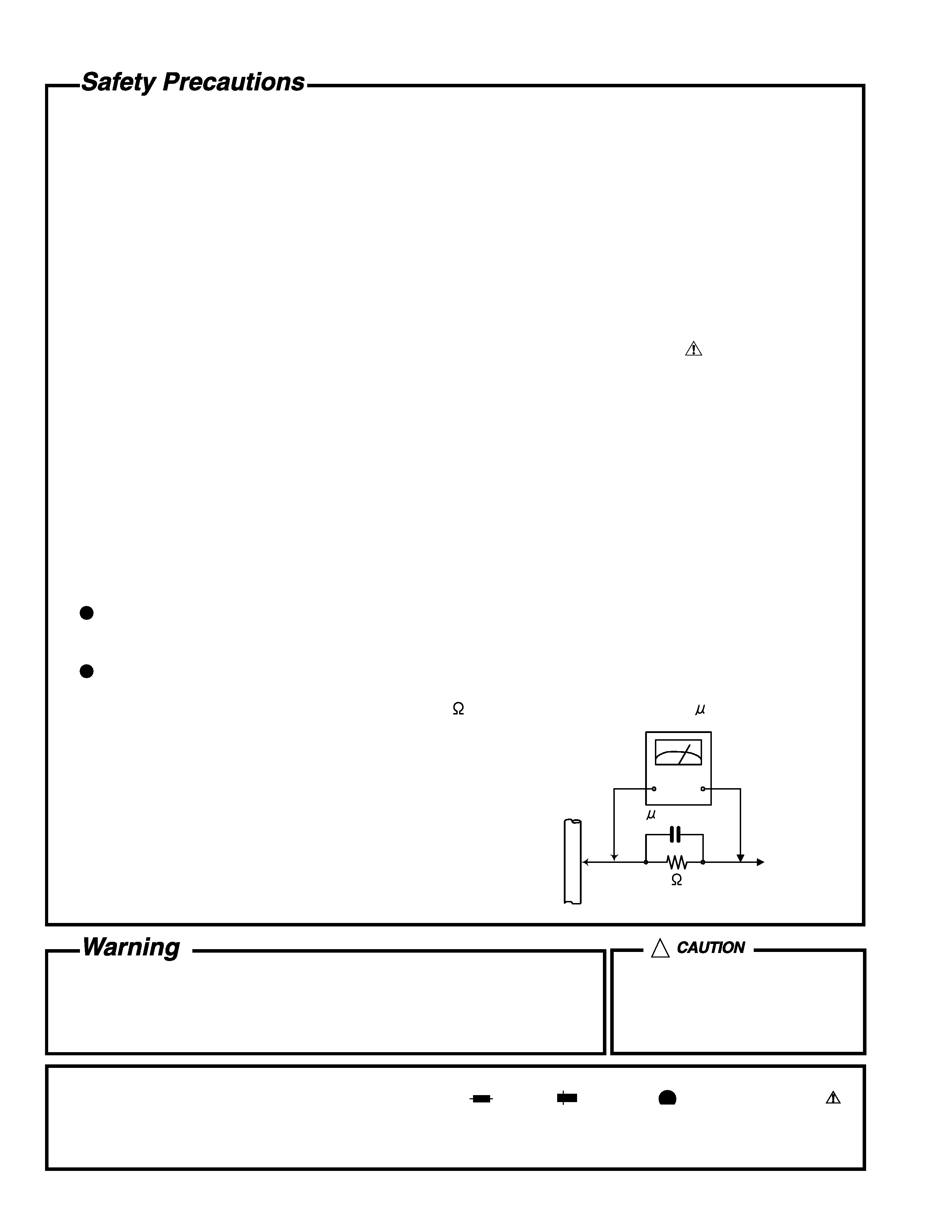
5. Leakage currnet check (Electrical shock hazard testing)
After re-assembling the product, always perform an isolation check on the exposed metal parts of the product
(antenna terminals, knobs, metal cabinet, screw heads, headphone jack, control shafts, etc.) to be sure the
product is safe to operate without danger of electrical shock.
Do not use a line isolation transformer during this check.
Plug the AC line cord directly into the AC outlet. Using a "Leakage Current Tester", measure the leakage
current from each exposed metal parts of the cabinet, particularly any exposed metal part having a return
path to the chassis, to a known good earth ground. Any leakage current must not exceed 0.5mA AC (r.m.s.).
Alternate check method
Plug the AC line cord directly into the AC outlet. Use an AC voltmeter having, 1,000 ohms per volt or more
sensitivity in the following manner. Connect a 1,500
10W resistor paralleled by a 0.15 F AC-type capacitor
between an exposed metal part and a known good earth ground.
Measure the AC voltage across the resistor with the AC
voltmeter.
Move the resistor connection to each exposed metal part,
particularly any exposed metal part having a return path to
the chassis, and meausre the AC voltage across the resistor.
Now, reverse the plug in the AC outlet and repeat each
measurement. Voltage measured any must not exceed 0.75 V
AC (r.m.s.). This corresponds to 0.5 mA AC (r.m.s.).
1. This equipment has been designed and manufactured to meet international safety standards.
2. It is the legal responsibility of the repairer to ensure that these safety standards are maintained.
3. Repairs must be made in accordance with the relevant safety standards.
4. It is essential that safety critical components are replaced by approved parts.
5. If mains voltage selector is provided, check setting for local voltage.
Good earth ground
Place this
probe on
each exposed
metal part.
AC VOLTMETER
(Having 1000
ohms/volts,
or more sensitivity)
1500
10W
0.15 F AC TYPE
!
Burrs formed during molding may
be left over on some parts of the
chassis. Therefore, pay attention to
such burrs in the case of
preforming repair of this system.
In regard with component parts appearing on the silk-screen printed side (parts side) of the PWB diagrams, the
parts that are printed over with black such as the resistor (
), diode (
) and ICP (
) or identified by the " "
mark nearby are critical for safety.
When replacing them, be sure to use the parts of the same type and rating as specified by the manufacturer.
(Except the JC version)
RX-8010RBK/ RX-8012RSL
1-3
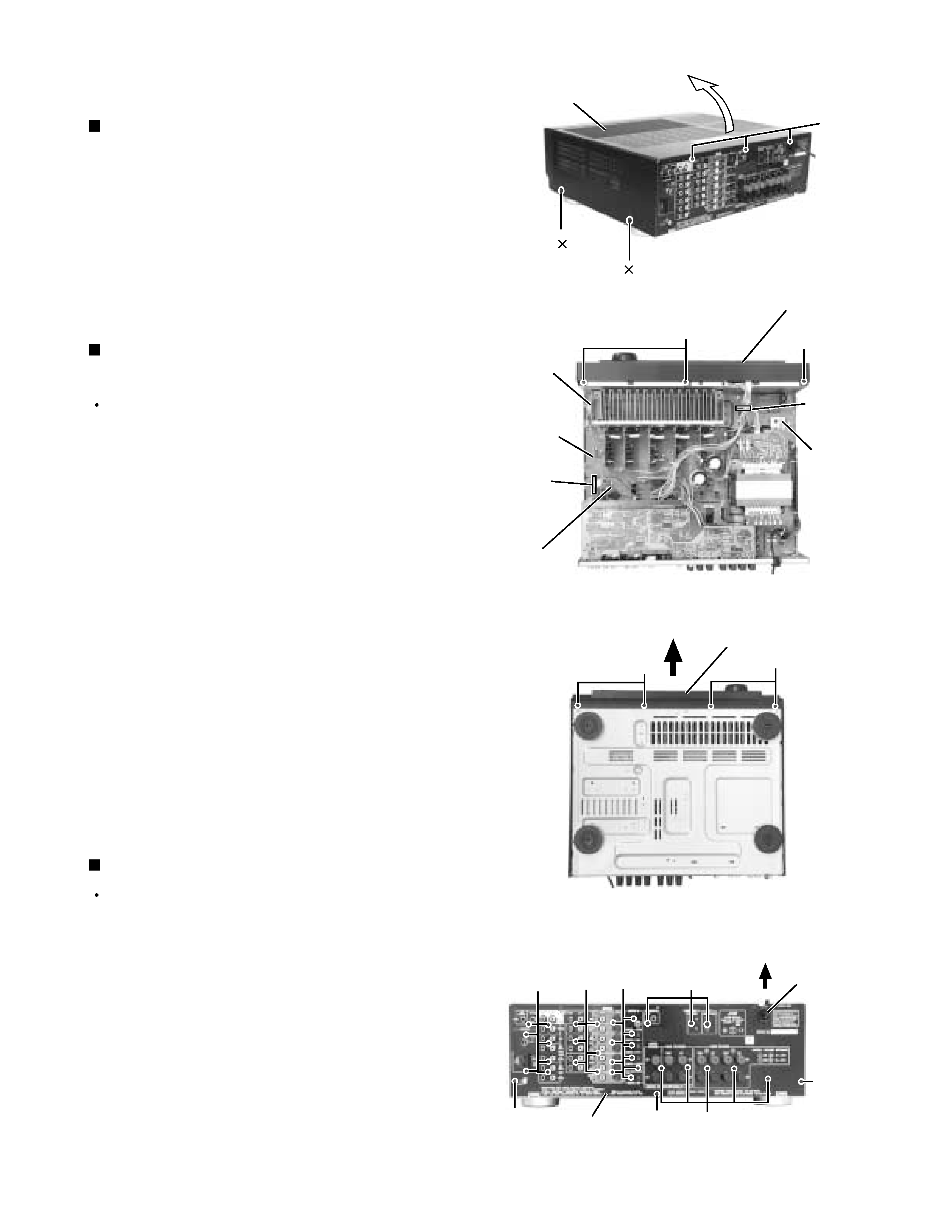
Remove the four screws A attaching the top cover
on both sides of the body.
Remove the three screws B on the back of the body.
Remove the top cover from behind in the direction of
the arrow while pulling both sides outward.
1.
2.
3.
Disassembly method
Removing the top cover (See Fig.1)
Prior to performing the following procedure, remove
the top cover.
Remove the power cord stopper from the rear panel
by moving it in the direction of the arrow.
Remove the thirty one screws E attaching the each
boards to the rear panel on the back of the body.
Remove the three screws F attaching the rear panel
on the back of the body.
1.
2.
3.
Removing the rear panel (See Fig.4)
Prior to performing the following procedure, remove
the top cover.
Disconnect the card wire from connector CN400 on
the audio board and CN402 on the power supply
board in the front panel assembly.
Cut off the tie band fixing the harness.
Remove the three screws C
attaching the front
panel assembly.
Remove the four screws D attaching the front panel
assembly on the bottom of the body. Detach the front
panel assembly toward the front.
1.
2.
3.
4.
Removing the front panel assembly
(See Fig.2 and 3)
Fig.1
Fig.2
Fig.3
Fig.4
A 2
A 2
B
Top cover
C
Power
supply
board
Audio board
CN400
Main
board
Tie band
D
E
F
E
F
F
Cord stopper
C
Front panel assembly
Front panel assembly
D
Rear panel
CN402
E
E
E
RX-8010RBK/ RX-8012RSL
1-4
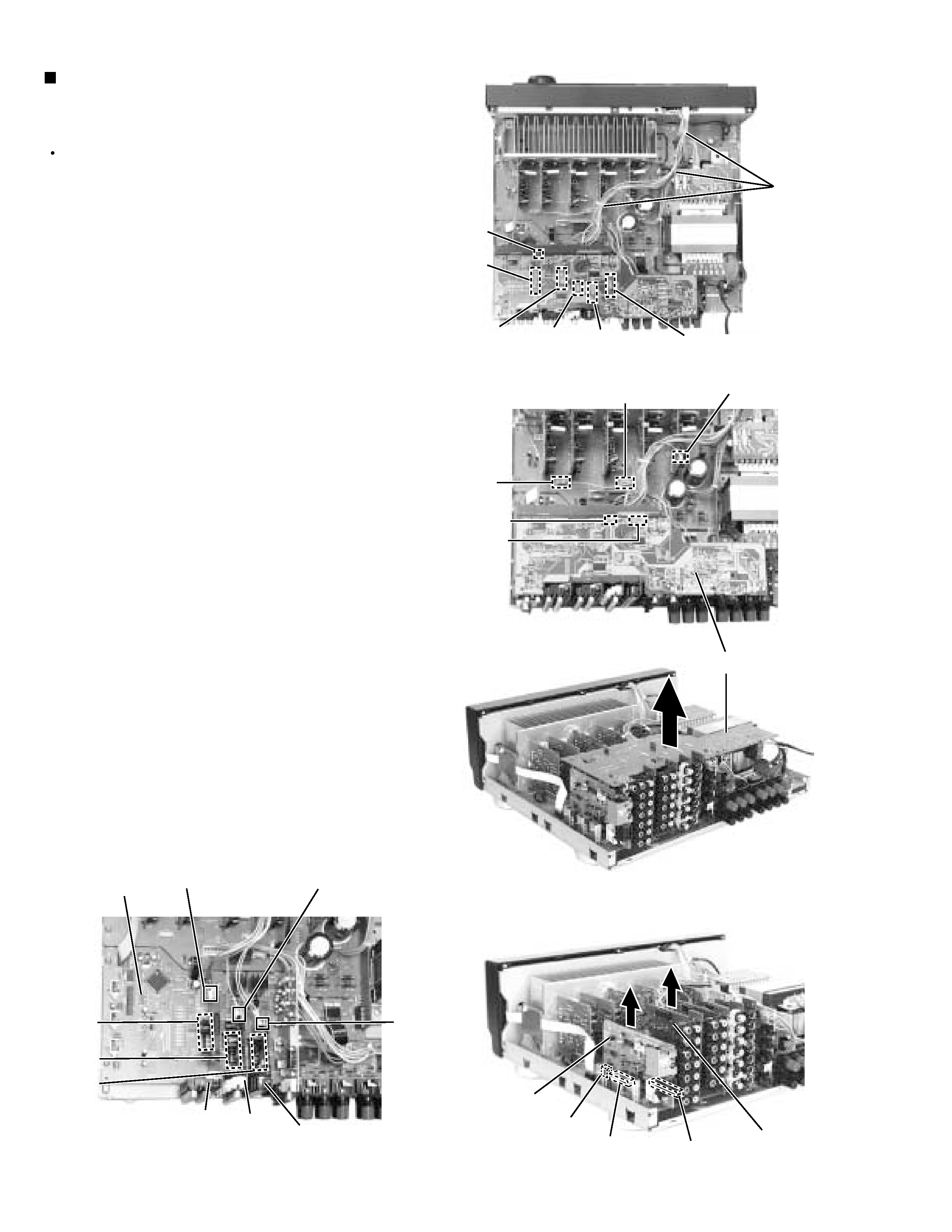
Prior to performing the following procedure, remove
the top cover and the rear panel.
Cut off the tie band fixing the harness.
Extract the plastic rivet a, which prevents the PWB
from pulling out, from the audio input board.
Disconnect the connect CN501, CN243, CN205,
CN381, CN361 on the DVD board.
Disconnect the harness from connector CN721,
CN722 and CN723.
Disconnect the tuner board and audio board from
connector CN101, CN102 and CN301 on the audio
board.
Pull out the video audio board, video board, S-video
board.
Disconnect the DSP board from connector CN601 on
the audio board.
1.
2.
3.
4.
5.
6.
7.
Removing each board connected to the
rear side of the audio board
(See Fig.5 to 11)
Fig.5
Fig.6
Fig.8
Tie band
CN101
CN723
CN361
CN381
CN243
Video
board
Tuner
board
CN501
S Video
board
CN721
CN722
CN205
Fig.9
CN301
CN206
CN416
CN244
CN303
CN201
CN241
Audio
board
CN731
CN732
Fig.7
DVD board
Audio input
board
Video audio
board
CN102
Plastic
rivet a
RX-8010RBK/ RX-8012RSL
1-5
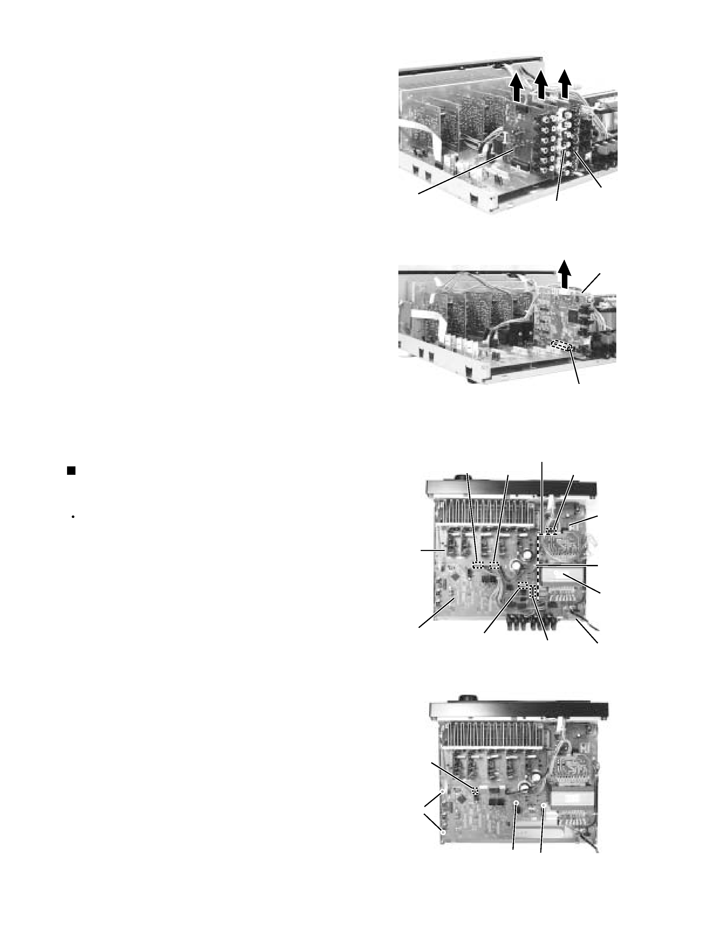
Prior to performing the following procedure, remove
the top cover and the rear panel.
Removing the audio board
(See Fig.12 and 13)
Disconnect the harness from connector CN813 and
CN814 on the main board.
Disconnect the card wire from connector CN931 and
CN932 on the audio board.
Cut off the tie band fixing the harness.
Disconnect the relay board from the audio board and
the power supply board. (CN71,CN81)
Disconnect the card wire from connector CN831 on
the main board.
Remove the three screws G
attaching the audio
board assembly.
Remove the screw H
attaching the audio board
assembly.
1.
2.
3.
4.
5.
6.
7.
Fig.10
Fig.11
power
supply
board
Power / Fuse
board
Relay board
Audio board
CN71
CN81
H
CN814
CN813
CN931/ 932
Power
transformer
G
G
Tie band
CN831
Main
board
Fig.12
DSP board
CN601
Video
board
S Video
board
Video audio
board
Fig.13