SERVICE MANUAL
AUDIO/VIDEO CONTROL RECEIVER
No.21097
Apr. 2002
COPYRIGHT
2002 VICTOR COMPANY OF JAPAN, LTD.
RX-7520VBK
RX-7520VBK
Contents
Safety precautions --------------------------------------------------------1-2
Importance administering point on the safety --------------------- 1-3
Disassembly method -----------------------------------------------------1-4
Adjustment method -------------------------------------------------------1-9
Description of major ICs -------------------------------------------------1-10~24
Area suffix
C ------------------- Canada
DVD
VCR
TV SOUND
ADJUST
RX-7520V AUDIO/VIDEO CONTROL RECEIVER
SETTING
MASTER VOLUME
CONTROL
DOWN
UP
CD
TAPE/CDR
SOURCE NAME
BASS BOOST
INPUT
ANALOG/DIGITAL
SPEAKERS ON/OFF
SURROUND MODE
PHONES
SURROUND ON/OFF
FM/AM TUNING
STANDBY
STANDBY/ON
FM/AM PRESET
FM MODE
MEMORY
INPUT ATT
AM
DVD MULTI
FM
12
COMPULINK
Remote
FM MODE
RX-7520VBK
1-2
1. This design of this product contains special hardware and many circuits and components specially for safety
purposes. For continued protection, no changes should be made to the original design unless authorized in
writing by the manufacturer. Replacement parts must be identical to those used in the original circuits. Services
should be performed by qualified personnel only.
2. Alterations of the design or circuitry of the product should not be made. Any design alterations of the product
should not be made. Any design alterations or additions will void the manufacturer`s warranty and will further
relieve the manufacture of responsibility for personal injury or property damage resulting therefrom.
3. Many electrical and mechanical parts in the products have special safety-related characteristics. These
characteristics are often not evident from visual inspection nor can the protection afforded by them necessarily
be obtained by using replacement components rated for higher voltage, wattage, etc. Replacement parts which
have these special safety characteristics are identified in the Parts List of Service Manual. Electrical
components having such features are identified by shading on the schematics and by (
) on the Parts List in
the Service Manual. The use of a substitute replacement which does not have the same safety characteristics
as the recommended replacement parts shown in the Parts List of Service Manual may create shock, fire, or
other hazards.
4. The leads in the products are routed and dressed with ties, clamps, tubings, barriers and the like to be
separated from live parts, high temperature parts, moving parts and/or sharp edges for the prevention of
electric shock and fire hazard. When service is required, the original lead routing and dress should be
observed, and it should be confirmed that they have been returned to normal, after re-assembling.
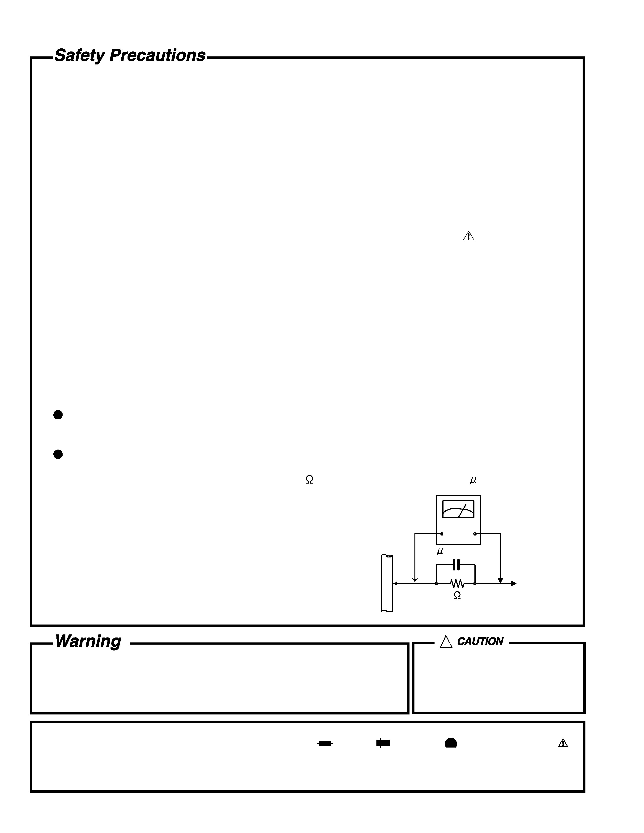
5. Leakage currnet check (Electrical shock hazard testing)
After re-assembling the product, always perform an isolation check on the exposed metal parts of the product
(antenna terminals, knobs, metal cabinet, screw heads, headphone jack, control shafts, etc.) to be sure the
product is safe to operate without danger of electrical shock.
Do not use a line isolation transformer during this check.
Plug the AC line cord directly into the AC outlet. Using a "Leakage Current Tester", measure the leakage
current from each exposed metal parts of the cabinet, particularly any exposed metal part having a return
path to the chassis, to a known good earth ground. Any leakage current must not exceed 0.5mA AC (r.m.s.).
Alternate check method
Plug the AC line cord directly into the AC outlet. Use an AC voltmeter having, 1,000 ohms per volt or more
sensitivity in the following manner. Connect a 1,500
10W resistor paralleled by a 0.15 F AC-type capacitor
between an exposed metal part and a known good earth ground.
Measure the AC voltage across the resistor with the AC
voltmeter.
Move the resistor connection to each exposed metal part,
particularly any exposed metal part having a return path to
the chassis, and meausre the AC voltage across the resistor.
Now, reverse the plug in the AC outlet and repeat each
measurement. Voltage measured any must not exceed 0.75 V
AC (r.m.s.). This corresponds to 0.5 mA AC (r.m.s.).
1. This equipment has been designed and manufactured to meet international safety standards.
2. It is the legal responsibility of the repairer to ensure that these safety standards are maintained.
3. Repairs must be made in accordance with the relevant safety standards.
4. It is essential that safety critical components are replaced by approved parts.
5. If mains voltage selector is provided, check setting for local voltage.
Good earth ground
Place this
probe on
each exposed
metal part.
AC VOLTMETER
(Having 1000
ohms/volts,
or more sensitivity)
1500
10W
0.15 F AC TYPE
!
Burrs formed during molding may
be left over on some parts of the
chassis. Therefore, pay attention to
such burrs in the case of
preforming repair of this system.
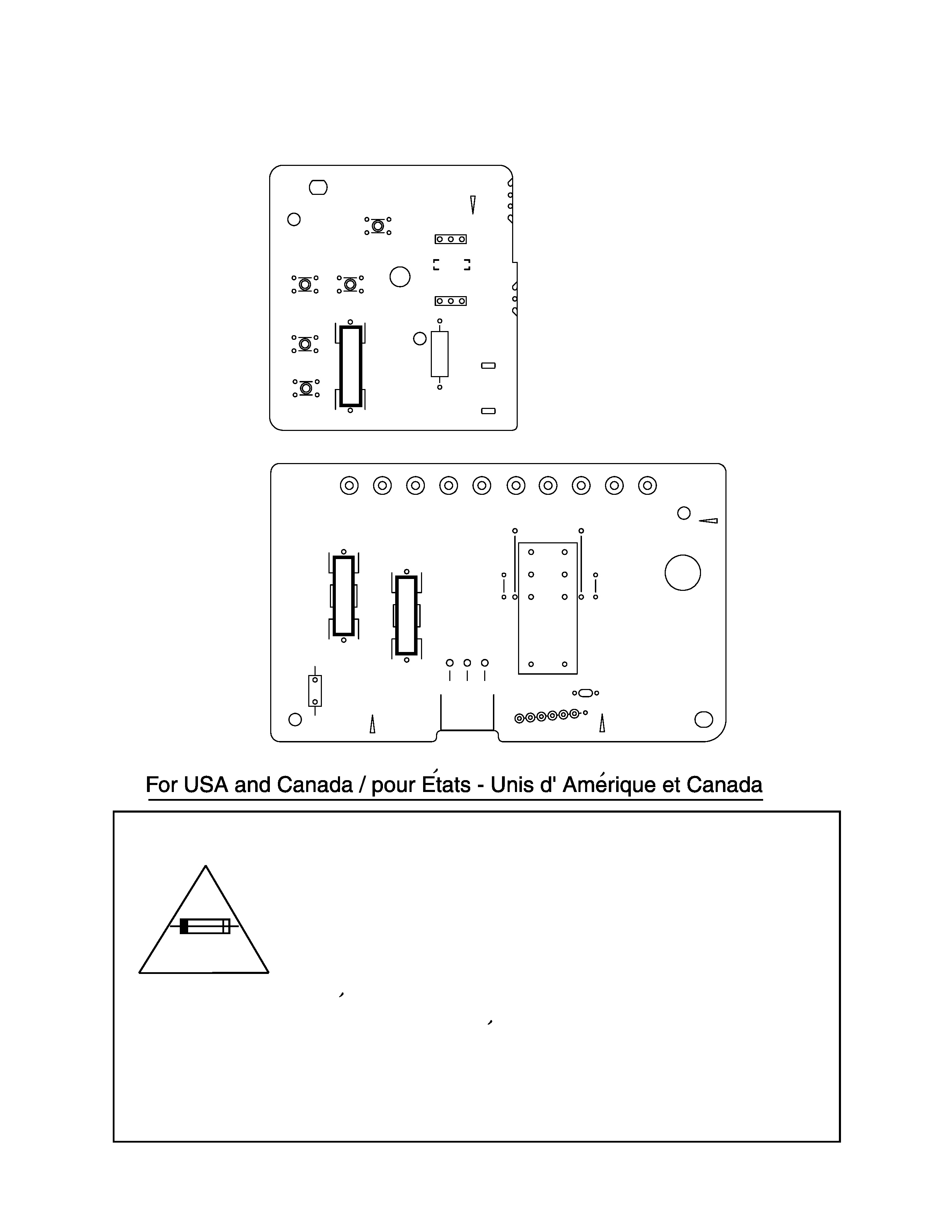
In regard with component parts appearing on the silk-screen printed side (parts side) of the PWB diagrams, the
parts that are printed over with black such as the resistor (
), diode (
) and ICP (
) or identified by the " "
mark nearby are critical for safety.
(This regulation does not correspond to J and C version.)
RX-7520VBK
1-3
Caution: For continued protection against risk of
fire, replace only with same type 6.3A/125V for
F201, 2A/125V for F202 and F203.
This symbol specifies type of fast operating fuse.
Precaution: Pour eviter risques de feux, remplacez
le fusible de surete de F201 comme le meme type
que 6.3A/125V, et 2A/125V pour F202 et F203.
Ce sont des fusibles suretes qui functionnes rapide.
^
Importance administering point on the safety
Secondary parts
Primary part
FC211
FC212
R1
EP1
B106
B105
B104
TA201
TA202
PW104
PW102
PW105
PW103
PW101
B103
B102
B101
B108
B107
B109
B110
CN251
D205
FC221
FC222
FC231
FC232
R201
RY201
110
111
112
113
114
120
121
122
130
131
B192
B191
B160
B159
6.3A-125V
2A-125V
2A-125V
F 201
F 203
F 202
LVA1029-C9
LVA1029-C7
6.3A-125V
RX-7520VBK
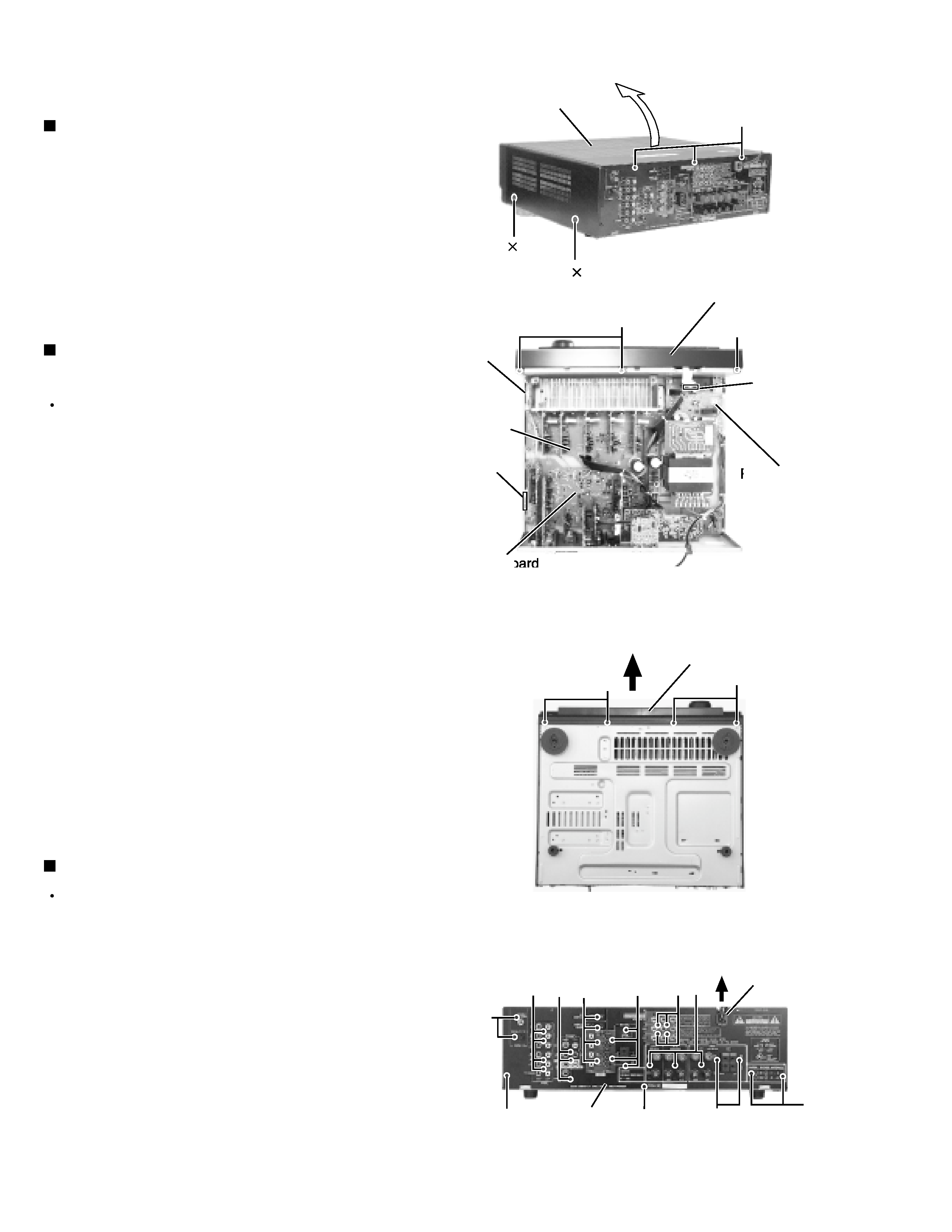
1-4
Remove the four screws A attaching the top cover on
both sides of the body.
Remove the three screws B on the back of the body.
Remove the top cover from behind in the direction of
the arrow while pulling both sides outward.
1.
2.
3.
Disassembly method
Removing the top cover (See Fig.1)
Prior to performing the following procedure, remove
the top cover.
Remove the power cord stopper from the rear panel
by moving it in the direction of the arrow.
Remove the twenty-six screws E attaching the each
boards to the rear panel on the back of the body.
Remove the four screws F attaching the rear panel
on the back of the body.
1.
2.
3.
Removing the rear panel (See Fig.4)
Prior to performing the following procedure, remove
the top cover.
Disconnect the card wire from connector CN402 on
the audio board and CN201 on the power supply
board in the front panel assembly.
Cut off the tie band fixing the harness.
Remove the three screws C attaching the front panel
assembly.
Remove the four screws D attaching the front panel
assembly on the bottom of the body. Detach the front
panel assembly toward the front.
1.
2.
3.
4.
Removing the front panel assembly
(See Fig.2 and 3)
Fig.1
Fig.2
Fig.3
Fig.4
A 2
A 2
B
Top cover
C
Power supply
board
Audio board
CN402
Main
board
Tie band
D
E
E
F
E
F
F
Cord stopper
C
Front panel assembly
Front panel assembly
D
Rear panel
CN201
E
E
E
E
E
RX-7520VBK
1-5
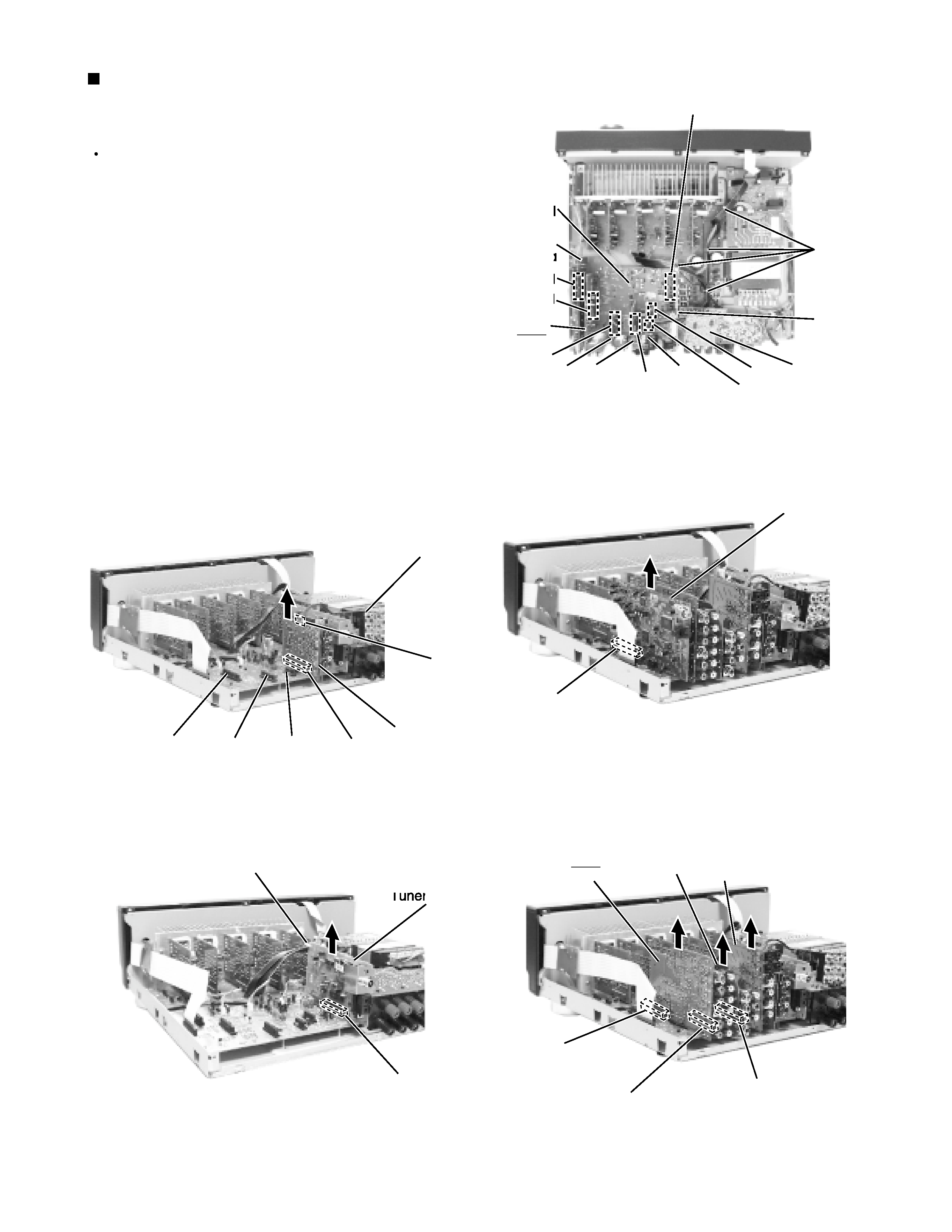
Prior to performing the following procedure, remove
the top cover and the rear panel.
Cut off the tie band fixing the harness.
Disconnect the DSP board from connector CN481 on
the audio board.
Disconnect
the
Component
video
board
from
connector CN511 on the S video board.
Disconnect the audio input board, DVD board Video
board and the S video board from connector CN421,
CN431, CN441 and CN461 on the audio board.
Disconnect the tuner board from connector CN411
on the audio board.
1.
2.
3.
4.
5.
Removing each board connected to the
rear side of the audio board
(See Fig.5 to 9)
Fig.5
Fig.6
Fig.7
Fig.8
CN411
Tie band
DSP
board
DVD
board
Video
board
Tuner
board
Audio
input
board
DSP board
CN481
CN441
CN431
CN421
CN481
CN421
CN431
CN441
CN411
Tie band
CN421
CN431
CN441
Audio
input
board
DVD
board
Video
board
Tuner board
Audio
board
CN461
S Video
board
CN461
S Video
board
Component
video board
CN511
Fig.9
Component
video board
CN511