For Customer Use:
Enter below the Model No. and Serial
No. which are located either on the rear,
bottom or side of the cabinet. Retain this
information for future reference.
Model No.
Serial No.
LVT1170-001B
[J]
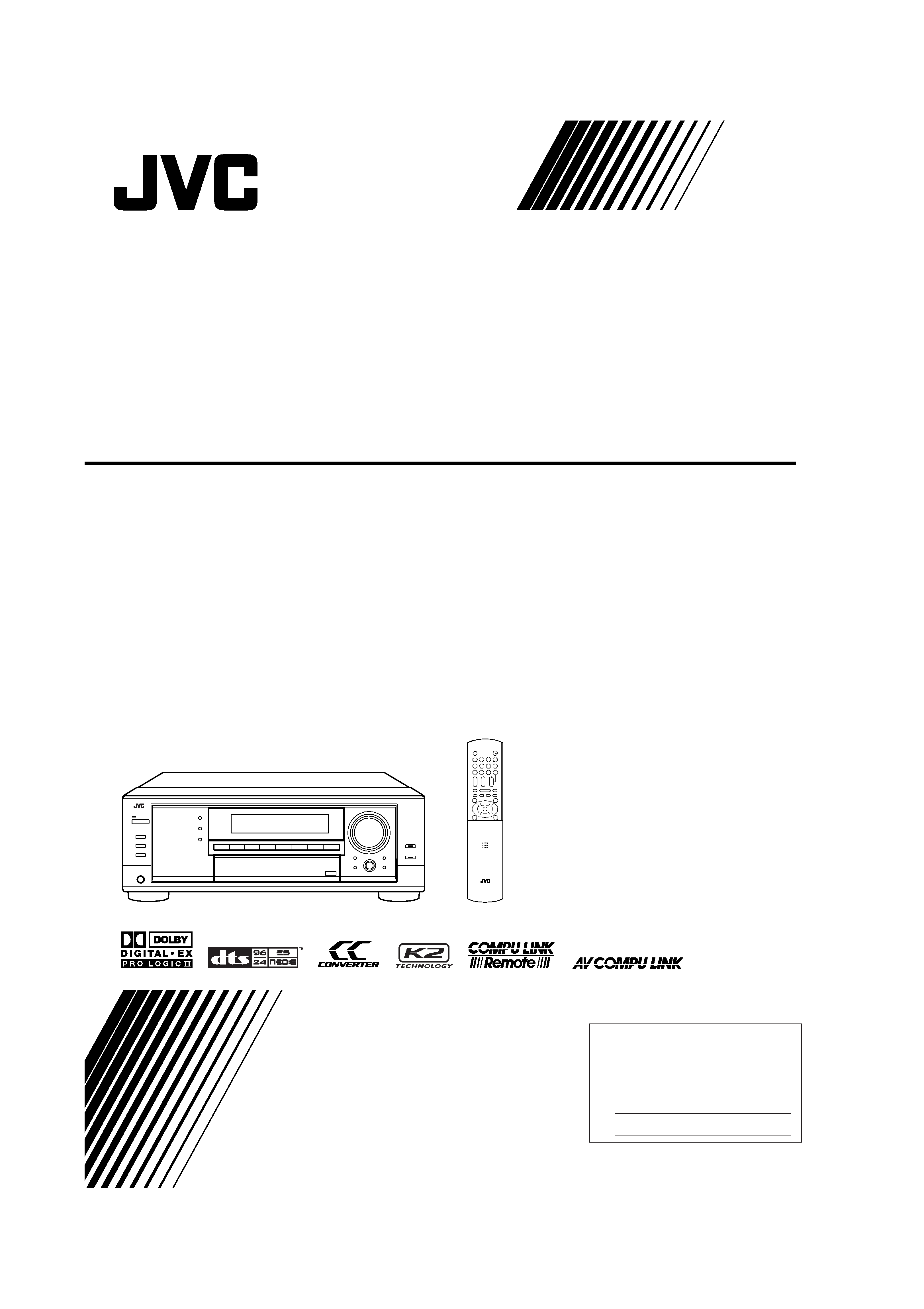
RX-7040B/RX-7042S
AUDIO/VIDEO CONTROL RECEIVER
INSTRUCTIONS
Cover_2_7040[J]
04.1.21, 15:54
1
G-1
CAUTION
To reduce the risk of electrical shocks, fire, etc.:
1.
Do not remove screws, covers or cabinet.
2.
Do not expose this appliance to rain or moisture.
ATTENTION
Afin d'éviter tout risque d'électrocution, d'incendie, etc.:
1.
Ne pas enlever les vis ni les panneaux et ne pas ouvrir le
coffret de l'appareil.
2.
Ne pas exposer l'appareil à la pluie ni à l'humidité.
Warnings, Cautions and Others/
Mises en garde, précautions et indications diverses
Caution
STANDBY/ON button!
Disconnect the mains plug to shut the power off completely. The
STANDBY/ON button in any position does not disconnect
the mains line. The power can be remote controlled.
AttentionCommutateur
STANDBY/ON!
Déconnecter la fiche de secteur pour couper complètement le
courant. Le commutateur
STANDBY/ON ne coupe jamais
complètement la ligne de secteur, quelle que soit sa position. Le
courant peut être télécommandé.
Note to CATV system installer:
This reminder is provided to call the CATV system installer's
attention to Section 820-40 of the NEC which provides guidelines for
proper grounding and, in particular, specifies that the cable ground
shall be connected to the grounding system of the building, as close
to the point of cable entry as practical.
For Canada/pour Le Canada
THIS DIGITAL APPARATUS DOES NOT EXCEED THE CLASS B
LIMITS FOR RADIO NOISE EMISSIONS FROM DIGITAL APPA-
RATUS AS SET OUT IN THE INTERFERENCE-CAUSING
EQUIPMENT STANDARD ENTITLED "DIGITAL APPARATUS,"
ICES-003 OF THE DEPARTMENT OF COMMUNICATIONS.
CET APPAREIL NUMERIQUE RESPECTE LES LIMITES DE
BRUITS RADIOELECTRIQUES APPLICABLES AUX APPAREILS
NUMERIQUES DE CLASSE B PRESCRITES DANS LA NORME
SUR LE MATERIEL BROUILLEUR; "APPAREILS NUMERIQUES",
NMB-003 EDICTEE PAR LE MINISTRE DES COMMUNICATIONS.
CAUTION:
TO REDUCE THE RISK OF ELECTRIC SHOCK.
DO NOT REMOVE COVER (OR BACK)
NO USER SERVICEABLE PARTS INSIDE.
REFER SERVICING TO QUALIFIED SERVICE PERSONNEL.
RISK OF ELECTRIC SHOCK
DO NOT OPEN
The lightning flash with arrowhead symbol,
within an equilateral triangle is intended to
alert the user to the presence of uninsulated
"dangerous voltage" within the product's
enclosure
that
may
be
of
sufficient
magnitude to constitute a risk of electric
shock to persons.
The exclamation point within an equilateral
triangle is intended to alert the user to the
presence
of
important
operating
and
maintenance (servicing) instructions in the
literature accompanying the appliance.
CAUTION
WARNING: TO REDUCE THE RISK OF FIRE
OR ELECTRIC SHOCK, DO NOT EXPOSE
THIS APPLIANCE TO RAIN OR MOISTURE.
CAUTION: TO PREVENT ELECTRIC SHOCK, MATCH WIDE
BLADE OF PLUG TO WIDE SLOT, FULLY INSERT.
ATTENTION: POUR EVITER LES CHOCS ELECTRIQUES,
INTRODUIRE LA LAME LA PLUS LARGE DE LA FICHE DANS LA
BORNE CORRESPONDANTE DE LA PRISE ET POUSSER
JUSQUAU FOND.
For U.S.A
This equipment has been tested and found to comply with the limits
for a Class B digital device, pursuant to part 15 of the FCC Rules.
These limits are designed to provide reasonable protection against
harmful interference in a residential installation.
This equipment generates, uses and can radiate radio frequency
energy and, if not installed and used in accordance with the
instructions,
may
cause
harmful
interference
to
radio
communications. However, there is no guarantee that interference
will not occur in a particular installation. If this equipment does cause
harmful interference to radio or television reception, which can be
determined by turning the equipment off and on, the user is
encouraged to try to correct the interference by one or more of the
following measures:
Reorient or relocate the receiving antenna.
Increase the separation between the equipment and receiver.
Connect the equipment into an outlet on a circuit different from that
to which the receiver is connected.
Consult the dealer or an experienced radio/TV technician for help.
Safety_7040[J]
04.1.21, 15:54
1

1
Table of Contents
Basic Settings ........................................... 21
Quick Speaker Setup ................................................................ 21
Basic Setting Items ................................................................... 22
Basic Procedure ........................................................................ 23
Setting the speakers ........................................................... 23
Setting the speaker distance ............................................... 24
Setting the bass sounds ...................................................... 24
Selecting the main or sub channel ..................................... 25
Setting for easy and effective surround operations ............ 25
Setting the digital input terminals ...................................... 25
Setting the component video input .................................... 26
Memorizing the volume level for each source ................... 26
Adjusting Sound ........................................ 27
Basic Adjustment Items ............................................................ 27
Basic Procedure ........................................................................ 27
Adjusting the equalization patterns .................................... 28
Adjusting the speaker output levels ................................... 28
Adjusting the sound parameters
for the surround and DSP modes ................................. 28
Using the Surround Modes .......................... 30
Reproducing Theater Ambience ................................................ 30
Introducing the Surround Modes ............................................. 30
Surround Modes Applicable to the Various Software .............. 32
Activating the Surround Modes ............................................... 33
7 Activating the EX/ES setting ............................................ 33
7 Activating the surround modes automatically .................. 33
7 Activating the surround modes manually ......................... 33
Using the DSP Modes ................................ 34
Reproducing the Sound Field ................................................... 34
Introducing the DSP Modes ..................................................... 34
Activating the DSP Modes ....................................................... 35
Using the DVD MULTI Playback Mode .......... 36
Activating the DVD MULTI Playback Mode .......................... 36
COMPU LINK Remote Control System ......... 37
AV COMPU LINK Remote Control System .... 38
Operating JVC's Audio/Video Components ... 40
Operating Audio Components .................................................. 40
Operating Video Components .................................................. 41
Operating Other Manufacturers'
Video Equipment .................................... 42
Troubleshooting ......................................... 45
Specifications ............................................ 46
Introduction ................................................ 2
Features ...................................................................................... 2
Precautions ................................................................................. 2
Parts Identification ...................................... 3
Getting Started ........................................... 6
Checking the Supplied Accessories ........................................... 6
Putting Batteries in the Remote Control .................................... 6
Connecting the FM and AM Antennas ....................................... 6
Connecting the Speakers and Subwoofer ................................... 7
Connecting Audio/Video Components ....................................... 9
7 Analog connections ............................................................ 9
7 Digital connections ........................................................... 12
Connecting the Power Cord ..................................................... 12
Basic Operations ....................................... 13
Daily Operational Procedure .................................................... 13
Turning On the Power .............................................................. 13
Selecting the Source to Play ..................................................... 13
Adjusting the Volume ............................................................... 14
Selecting the Front Speakers .................................................... 15
Turning On and Off the Subwoofer Sound .............................. 15
Selecting the Analog or Digital Input Mode ............................ 15
Setting the Dynamic Range ...................................................... 16
Attenuating the Input Signal .................................................... 16
Turning Analog Direct On and Off .......................................... 17
Making Sounds Natural ............................................................ 17
Changing the Source Name ...................................................... 17
Reinforcing the Bass ................................................................ 18
Muting the Sound ..................................................................... 18
Changing the Display Brightness ............................................. 18
Using the Sleep Timer .............................................................. 18
Receiving Radio Broadcasts ........................ 19
Tuning in to Stations Manually ................................................ 19
Using Preset Tuning ................................................................. 19
Selecting the FM Reception Mode ........................................... 20
This mark indicates that ONLY the remote control
CAN be used for the operation explained.
Remote
NOT
This mark indicates that the remote control
CANNOT be used for the operation explained.
Use the buttons and controls on the front panel.
01-12_7040[J]
04.1.21, 15:54
1

2
Introduction
We would like to thank you for purchasing one of our JVC products.
Before operating this unit, read this manual carefully and thoroughly to obtain the best possible performance
from your unit, and retain this manual for future reference.
Features
CC (Compensative Compression) converter
CC Converter eliminates jitter and ripples, achieving a drastic
reduction in digital distortion by processing the digital music data
in 24 bit-quantization and by expanding the sampling frequency to
128 kHz (for fs 32 kHz signals)/176.4 kHz (for fs 44.1 kHz
signals)/192 kHz (for fs 48 kHz signals). By using the CC
Converter, you can obtain a natural sound field from any source.
(See page 17 for details.)
K2 technology
K2 technology has been designed to enable natural audio
reproduction, achieving a drastic reduction in digital distortion
and creating original sound ambience with high precision.
Compatible with various audio formats including
DTS 96/24
This unit allow you to enjoy a audio format such as Dolby Digital
EX, Dolby Pro Logic II, DTS-ES, DTS Neo:6, and DTS 96/24.
· This unit is also compatible with Dual Mono signals recorded in
Dolby Digital and DTS discs.
DAP (Digital Acoustic Processor)
Sound field simulation technology allows precise ambience
recreation of existing theaters and halls. Thanks to the high-
performance DSP (Digital Signal Processor) and high-capacity
memory, you can enjoy multi-channel surround sound by playing
2-channel or multi-channel software according to the speaker
setting.
Multi-channel headphone virtual surround
sound--3D Headphone mode
The built-in headphone virtual surround system is compatible with
Multi-channel software like Dolby Digital, DTS Surround, etc.
Thanks to the signal processing algorithms used by the high-
performance DSP, you can enjoy a natural surround sound through
the headphones.
COMPU LINK/AV COMPU LINK remote control
systems
These COMPU LINK remote control systems allow you to
operate other JVC's audio/video components from this receiver.
Precautions
General
· Be sure your hands are dry.
· Turn the power off to all components.
· Read the manuals supplied with the components you are going to
connect.
Power sources
· When unplugging the receiver from the wall outlet, always pull
the plug, not the AC power cord.
· Do not handle the AC power cord with wet hands.
· If you are not going to operate the receiver for an extended period
of time, unplug the AC power cord from the wall outlet.
Locations
· Install the receiver in a location that is level and protected from
moisture and dust.
· The temperature around the receiver must be between 5°C and
35°C (23°F and 95°F).
Ventilation
High power amplifiers built in this receiver will generate heat inside
the cabinet. For safety, observe the following carefully.
· Make sure there is good ventilation around the receiver. Poor
ventilation could overheat and damage the receiver.
· Do not block the ventilation openings or holes. (If the ventilation
openings or holes are blocked by a newspaper or cloth, etc., the
heat may not be able to get out.)
Others
· Do not insert any metal object into the receiver.
· Should any metallic object or liquid fall onto the unit, unplug the
unit and consult your dealer before operating any further.
· Do not expose this apparatus to rain, moisture, dripping or
splashing and that no objects filled with liquids, such as vases
shall be placed on the apparatus.
· Do not disassemble the receiver or remove screws, covers, or
cabinet.
If anything goes wrong, unplug the AC power cord and consult your
JVC dealer.
01-12_7040[J]
04.1.21, 15:54
2
3
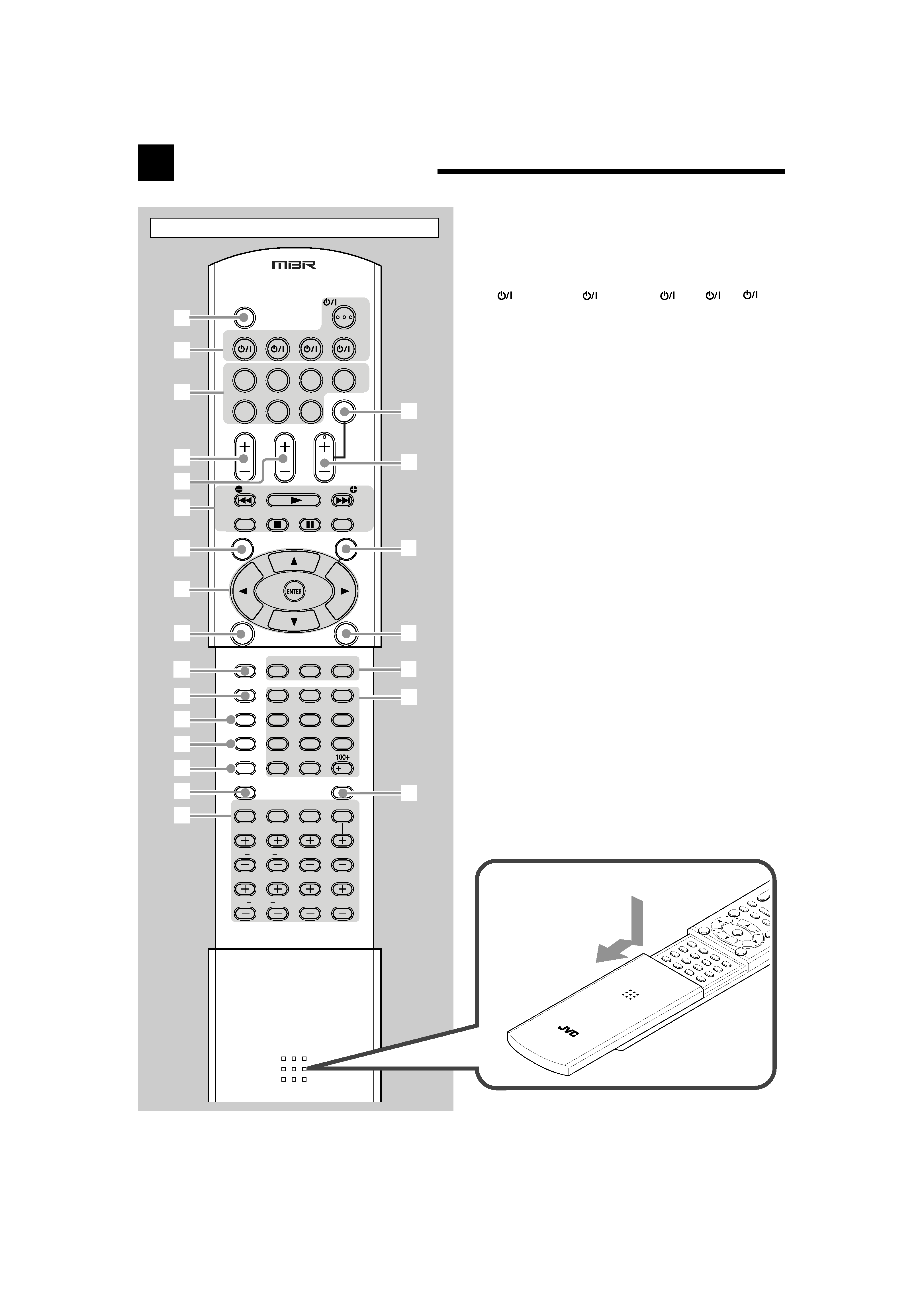
Parts Identification
See pages in parentheses for details.
1 DIMMER button (18, 40)
2 Standby/On buttons (13, 40 43)
AUDIO, DVD
, CATV/DBS
, VCR
, TV
3 Source selection buttons (13 15, 19, 20, 36, 40 43)
DVD MULTI, DVD, CD*, TAPE/CDR*, TV/DBS, VCR,
FM/AM*
* When you press one of these source selection buttons on
the remote control, the receiver automatically turns on.
4 TV VOL (volume) +/ button (41, 42)
5 CHANNEL +/ button (41 43)
6 Operating buttons for audio/video components (40, 41, 43)
REW
4, 3, FF ¢, 7, 8
Operating buttons for tuner (19, 40)
( TUNING, TUNING 9
REC PAUSE button (41, 43)
TV/VIDEO button (41, 42)
7 SURROUND button (33, 40)
8 Operating buttons for DVD player (40, 41, 43)
ENTER,
3, 2, 5,
9 DSP button (34, 35, 40)
p CC CONVERTER button (17, 40)
q EX/ES button (33, 40)
w ANALOG DIRECT button (17, 40)
e ANALOG/DIGITAL INPUT button (16, 40)
r MIDNIGHT MODE button (16, 40)
t CD-DISC button (40)
y Sound adjustment buttons (15, 18, 28, 29, 40)
u MUTING button (18, 40)
i VOLUME +/ button (14, 18, 40)
o DVD MENU button (41, 43)
; SURR (surround) /DSP OFF button (33, 35, 40)
a CATV/DBS CONT (control) button (42)
VCR CONT (control) button (41)
TAPE/CDR CONT (control) button (41)
s 10 keys for operating audio/video components (40 43)
10 keys for operating the tuner (20, 40)
d SLEEP button (18, 40)
1
2
3
4
5
6
7
8
e
u
i
o
;
a
s
d
r
w
q
p
9
t
y
DIMMER
DVD MULTI
DVD
CD
TAPE/CDR
MUTING
FM/AM
VCR
TV/DBS
TV VOL
CHANNEL VOLUME
TUNING
/FF
REW/
TUNING
TV/VIDEO
DVD MENU
SURROUND
SURR/DSP
OFF
DSP
CC CONVERTER CATV/DBS
VCR
TAPE/CDR
EX/ES
ANALOG
ANALOG/DIGITAL
MIDNIGHT
RETURN FM MODE
CD-DISC
SLEEP
TEST
BASS
BOOST
CENTER
TONE
D.EQ FREQ
LR
FRONT
CENTER D.EQ LEVEL
LR
SURR
S.BACK
SUBWFR
CONT
CONT
CONT
12
3
45
6
7/P
89
10
0
10
DIRECT
INPUT
MODE
TV
VCR
CATV/DBS
DVD
REC PAUSE
AUDIO
A/V
CONTR
OL RECEIVER
Remote Control
To open the cover of the
remote control, push here
then slide downward.
01-12_7040[J]
04.1.21, 15:54
3