For Customer Use:
Enter below the Model No. and Serial
No. which are located either on the rear,
bottom or side of the cabinet. Retain this
information for future reference.
Model No.
Serial No.
LVT0396-001A
[J]
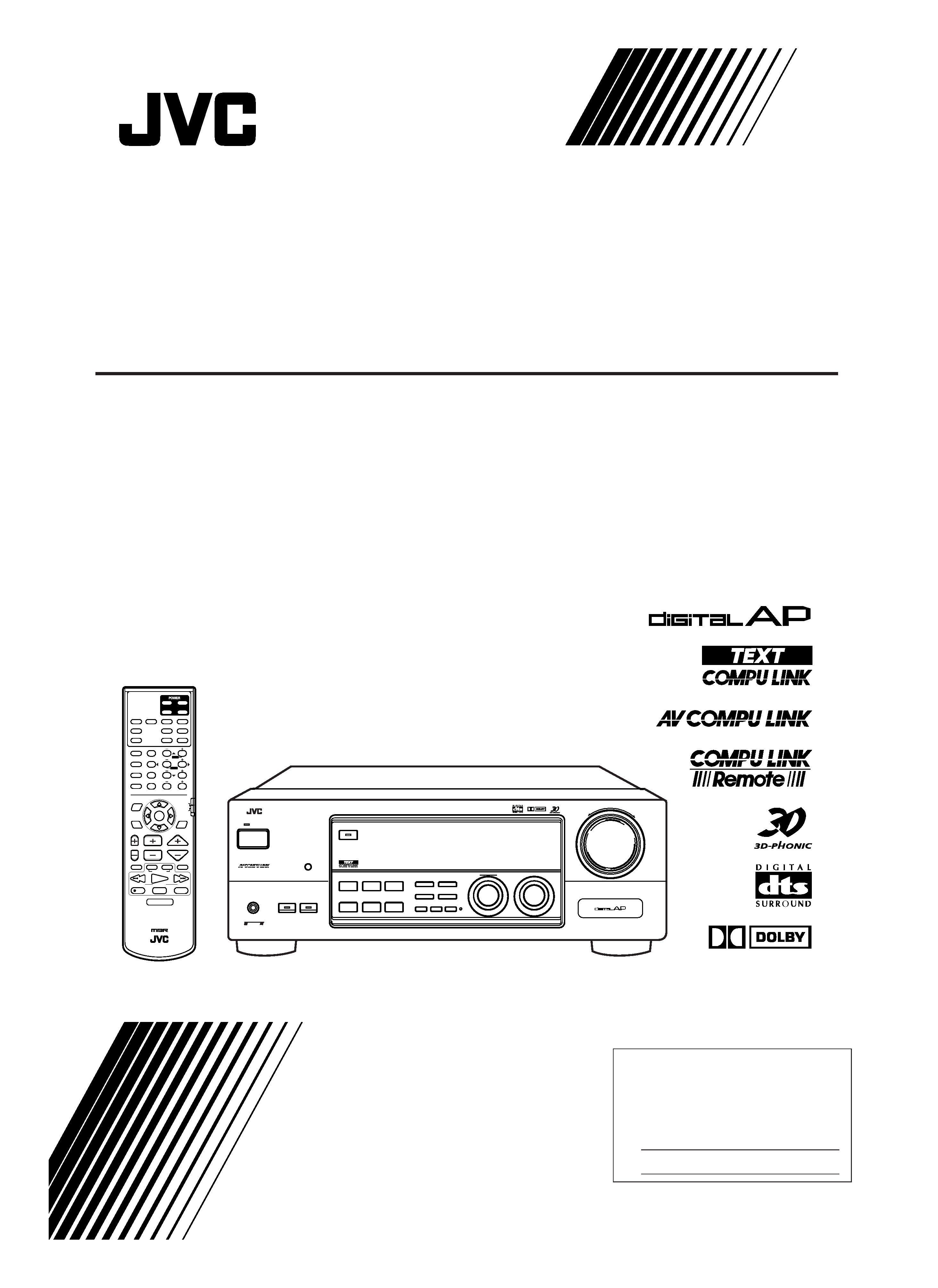
RX-7000VBK
INSTRUCTIONS
AUDIO/VIDEO CONTROL RECEIVER
DIGITAL
RM-SRX7000J
REMOTE CONTROL
CONTROL
CHANNEL
VOLUME
TV VOL
TUNING
STOP
PAUSE
FF/
/REW
VCR
TV/VIDEO
TAPE/MD
MUTING
REC
PLAY
DOWN
UP
AUDIO
TV
DVD
DVD MUILTI
CD
TAPE/MD
TV/DBS
PHONO
FM/AM
VCR
ANALOG/DIGITAL
SURROUND
CENTER
SURROUND
TEST
REAR-L
CD-DISC
MODE
ON/OFF
EFFECT
REAR-R
SOUND
SEA MODE
SUBWOOFER
RETURN
SET
MENU
AUDIO/
TV/VCR
EXIT
TEXT
DISPLAY
SLEEP
12
3
45
6
7/P
89
10
0
+10
100+
FM MODE
CATV/DBS
MENU
MENU
ENTER
ENTER
CATV/DBS
VCR
+
RX-7000V
AUDIO/VIDEO CONTROL RECEIVER
POWER
STANDBY
SPEAKERS
12
PHONES
SURROUND ON/OFF
DSP MODE
BALANCE/SURROUND
ADJUST
SEA MODE
SEA ADJUST
SETTING
MULTI JOG
MASTER VOLUME
SOURCE SELECTOR
THEATER
LIVE CLUB
DANCE CLUB
HALL
PAVILION
INPUT
ANALOG/DIGITAL
FM/AM TUNING
TUNER PRESET
TUNER/SEA MEMORY
FM MODE
DVD
TV SOUND/DBS
PHONO
TAPE/MD
VCR
FM
AM
CD
SOUND SELECT
INPUT ATT.
BASS BOOST ONETOUCHOPERATION
SOURCENAME
COMPULINK
Remote
DIGITAL
RX-7000V[J]COVER/f
00.1.12, 11:11 AM
1
G-1
Warnings, Cautions and Others
RX-7000VBK
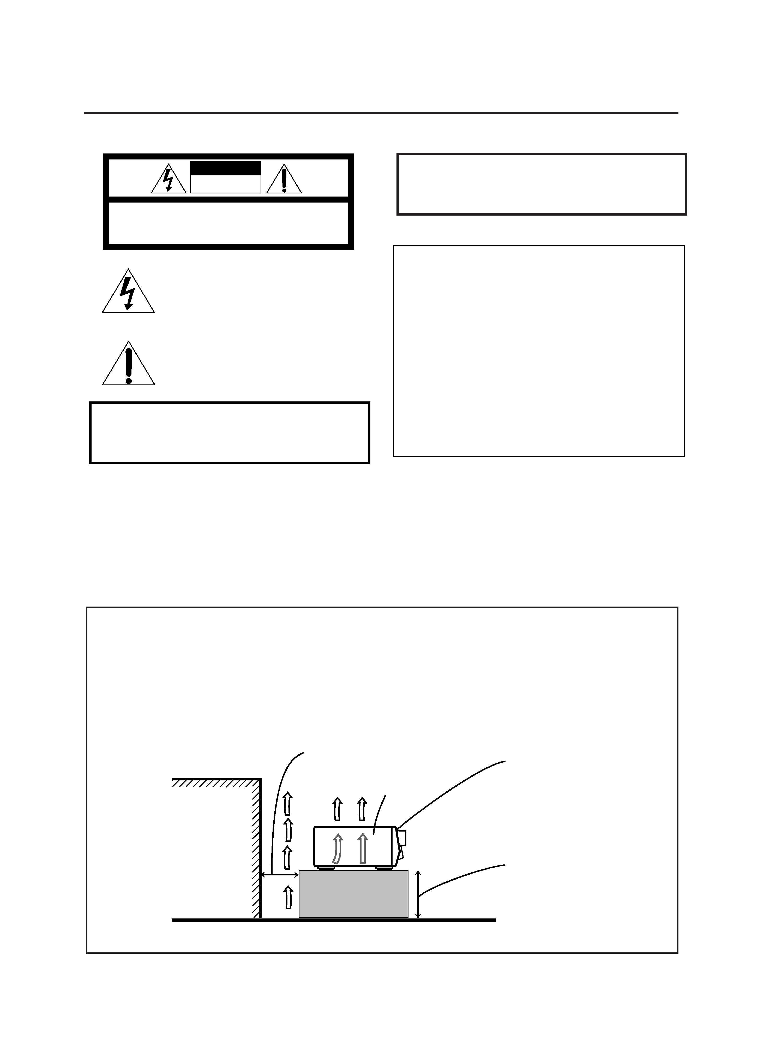
Floor
Spacing 15 cm or more
Stand height 15 cm or more
Wall or obstructions
Front
Caution: Proper Ventilation
To avoide risk of electric shock and fire and to protect from damage.
Locate the apparatus as follows:
Front:
No obstructions open spacing.
Sides:
No obstructions in 10 cm from the sides.
Top:
No obstructions in 10 cm from the top.
Back:
No obstructions in 15 cm from the back
Bottom:
No obstructions, place on the level surface.
In addition, maintain the best possible air circulation as illustrated.
CAUTION:
TO REDUCE THE RISK OF ELECTRIC SHOCK.
DO NOT REMOVE COVER (OR BACK)
NO USER SERVICEABLE PARTS INSIDE.
REFER SERVICING TO QUALIFIED SERVICE PERSONNEL.
RISK OF ELECTRIC SHOCK
DO NOT OPEN
The lightning flash with arrowhead symbol,
within an equilateral triangle is intended to
alert the user to the presence of uninsulated
"dangerous voltage" within the product's
enclosure
that
may
be
of
sufficient
magnitude to constitute a risk of electric
shock to persons.
The exclamation point within an equilateral
triangle is intended to alert the user to the
presence
of
important
operating
and
maintenance (servicing) instructions in the
literature accompanying the appliance.
CAUTION
WARNING: TO REDUCE THE RISK OF FIRE
OR ELECTRIC SHOCK, DO NOT EXPOSE
THIS APPLIANCE TO RAIN OR MOISTURE.
CAUTION
To reduce the risk of electrical shocks, fire, etc.:
1. Do not remove screws, covers or cabinet.
2. Do not expose this appliance to rain or moisture.
Caution POWER switch!
Disconnect the mains plug to shut the power off completely. The
POWER switch in any position does not disconnect the mains line.
The power can be remote controlled.
For U.S.A.
This equipment has been tested and found to comply with the limits
for a Class B digital device, pursuant to part 15 of the FCC Rules.
These limits are designed to provide reasonable protection against
harmful interference in a residential installation.
This equipment generates, uses and can radiate radio frequency
energy and, if not installed and used in accordance with the
instructions,
may
cause
harmful
interference
to
radio
communications. However, there is no guarantee that interference
will not occur in a particular installation. If this equipment does cause
harmful interference to radio or television reception, which can be
determined by turning the equipment off and on, the user is
encouraged to try to correct the interference by one or more of the
following measures:
Reorient or relocate the receiving antenna.
Increase the separation between the equipment and receiver.
Connect the equipment into an outlet on a circuit different from that
to which the receiver is connected.
Consult the dealer or an experienced radio/TV technician for help.
RX-7000V[J]Safety/f
00.1.12, 11:11 AM
1

1
Table of Contents
Using the DSP Modes ................................ 21
Available DSP Modes According to the Speaker Arrangement .. 23
Adjusting the 3D-PHONIC Modes .......................................... 24
Adjusting the DAP Modes ....................................................... 24
Adjusting the Surround Modes ................................................ 25
Activating the DSP Modes ....................................................... 27
Using the DVD MULTI Playback Mode .......... 29
Activating the DVD MULTI Playback Mode .......................... 29
Using the On-Screen Menus ........................ 30
Selecting the Source to Play ..................................................... 30
Selecting Different Sources for Picture and Sound .................. 30
Activating the DSP Modes ....................................................... 30
Selecting the Analog or Digital Input Mode .............................. 30
Adjusting the Front Speaker Output Balance ........................... 31
Reinforcing the Bass ................................................................ 31
Attenuating the Input Signal .................................................... 31
Adjusting the Subwoofer Output Level .................................... 31
Adjusting the DSP Modes ........................................................ 31
Adjusting the DVD MULTI Playback Mode ........................... 32
Selecting Your Favorite SEA Mode ......................................... 32
Creating Your Own SEA Mode ................................................ 32
Setting the Basic Setting Items ................................................ 33
Operating the Tuner .................................................................. 33
Storing the Preset Stations ....................................................... 34
Assigning Names to Preset Stations ......................................... 34
COMPU LINK Remote Control System ......... 35
TEXT COMPU LINK Remote Control System .. 36
7 Showing the Disc Information on the TV Screen................. 37
7 Searching for a Disc (Only for the CD player) .................... 38
7 Entering the Disc Information .............................................. 39
AV COMPU LINK Remote Control System .... 41
Operating JVC's Audio/Video Components ... 43
Operating Audio Components .................................................. 43
Operating Video Components .................................................. 45
Operating Other Manufacturers' Video
Equipment ............................................ 46
Troubleshooting ......................................... 48
Specifications ............................................ 49
Parts Identification ...................................... 2
Getting Started ........................................... 3
Before Installation ...................................................................... 3
Checking the Supplied Accessories ........................................... 3
Connecting the FM and AM Antennas ....................................... 3
Connecting the Speakers ............................................................ 4
Connecting Audio/Video Components ....................................... 5
Connecting the Power Cord ....................................................... 9
Putting Batteries in the Remote Control .................................... 9
Basic Operations ....................................... 10
Turning the Power On and Off (Standby) ................................ 10
Selecting the Source to Play ..................................................... 10
Adjusting the Volume ............................................................... 11
Selecting the Front Speakers .................................................... 11
Muting the Sound ..................................................................... 12
Reinforcing the Bass ................................................................ 12
Attenuating the Input Signal .................................................... 12
Adjusting the Subwoofer Output Level .................................... 12
Basic Settings ........................................... 13
Recording a Source .................................................................. 13
Adjusting the Front Speaker Output Balance ........................... 13
Changing the Source Name ...................................................... 13
Setting the Subwoofer Information .......................................... 14
Setting the Speakers for the DSP Modes ................................. 14
Digital Input (DIGITAL IN) Terminal Setting ......................... 16
Selecting the Analog or Digital Input Mode ............................ 16
Showing the Text Information on the Display ......................... 17
Storing the Basic Settings and Adjustments -- One Touch
Operation ........................................................................... 17
Using the Sleep Timer .............................................................. 17
Receiving Radio Broadcasts ........................ 18
Tuning in Stations Manually .................................................... 18
Using Preset Tuning ................................................................. 18
Selecting the FM Reception Mode ........................................... 19
Assigning Names to Preset Stations ......................................... 19
Using the SEA Modes ................................ 20
Selecting Your Favorite SEA Mode ........................................... 20
Creating Your Own SEA Mode ................................................ 20
EN01-09.RX-7000V[J]/f
00.1.12, 11:36 AM
1
2
Parts Identification
Become familiar with the buttons and controls on the receiver before use.
Refer to the pages in parentheses for details.
+
AUDIO/VIDEO CONTROL RECEIVER
RX-7000V
POWER
STANDBY
SPEAKERS
12
PHONES
SURROUND ON/OFF
DSP MODE
BALANCE/SURROUND
ADJUST
SEA MODE
SEA ADJUST
SETTING
MULTI JOG
MASTER VOLUME
SOURCE SELECTOR
INPUT
ANALOG/DIGITAL
FM/AM TUNING
TUNER PRESET
TUNER/SEA MEMORY
FM MODE
DVD
TV SOUND/DBS
PHONO
TAPE/MD
VCR
FM
AM
THEATER
LIVE CLUB
DANCE CLUB
HALL
PAVILION
CD
SOUND SELECT
INPUT ATT.
BASS BOOST ONETOUCHOPERATION
SOURCENAME
COMPULINK
Remote
DIGITAL
1
2
34
5
6 7
8
9
p
d
s
a
;
o
i
u
y
t
r
e
w
q
RM-SRX7000J
REMOTE CONTROL
CONTROL
CHANNEL
VOLUME
TV VOL
TUNING
STOP
PAUSE
FF/
/REW
VCR
TV/VIDEO
TAPE/MD
MUTING
REC
PLAY
DOWN
UP
AUDIO
TV
TV/CATV/DBS
VCR 1
DVD
DVD MUILTI
CD
TAPE/MD
TV/DBS
PHONO
FM/AM
VCR
ANALOG/DIGITAL
SURROUND
CENTER
SURROUND
TEST
REAR-L
CD-DISC
MODE
ON/OFF
EFFECT
REAR-R
SOUND
SEA MODE
SUBWOOFER
RETURN
FM MODE
SET
MENU
AUDIO/
TV/VCR
EXIT
TEXT
DISPLAY
SLEEP
12
3
45
6
7/P
89
10
0
+10
100+
CATV/DBS
MENU
MENU
ENTER
ENTER
CATV/DBS
VCR
2
3
4
5
6
7
8
9
p
;
o
i
u
y
t
r
e
w
q
1
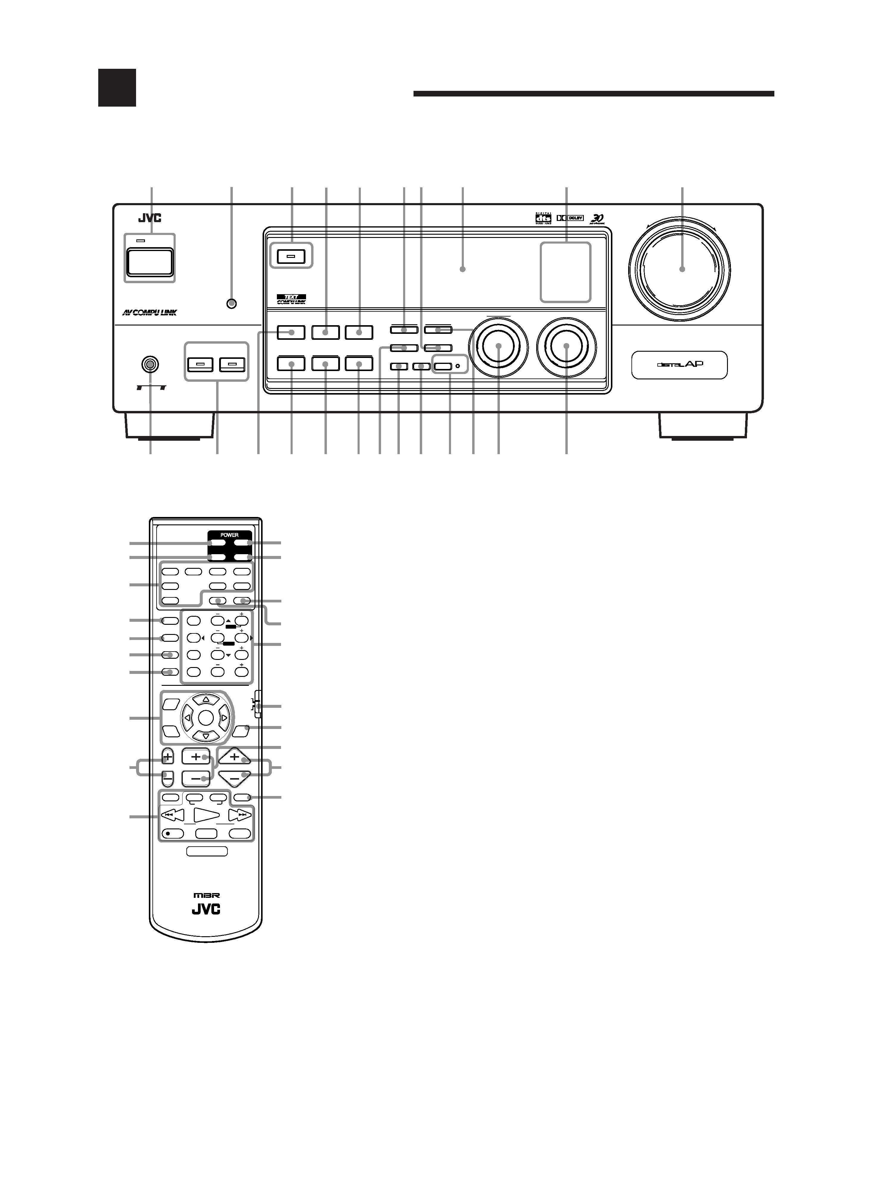
Front Panel
1 POWER button and STANDBY lamp (10)
2 Remote sensor (9)
3 SURROUND ON/OFF button and lamp (26, 27)
4 SEA MODE button (20)
5 INPUT ANALOG/DIGITAL button (16)
6 FM/AM TUNING button (18) *
7 FM MODE button (19)
8 Display (10)
9 Source lamps (10)
p MASTER VOLUME control (11)
q PHONES jack (12)
w SPEAKERS 1/2 buttons and lamps (11)
e DSP MODE button (24)
r BALANCE/SURROUND ADJUST button
(12, 13, 24) *
t SEA ADJUST button (20) *
y SETTING button (14 17) *
u TUNER/SEA MEMORY button (18 20)
i SOUND SELECT/INPUT ATT. button
(11, 12)
o BASS BOOST/SOURCE NAME button
(12, 13)
; ONE TOUCH OPERATION button and lamp
(17)
a TUNER PRESET button (19) *
s MULTI JOG control
What this control actually does depends on which
function you are trying to adjust. Before using
this control, select the function by pressing one
of the buttons marked with *.
d SOURCE SELECTOR control (10)
Remote Control
1 TV POWER button (45, 46)
2 VCR POWER button (45, 47)
3 Source selecting buttons (10)
DVD, DVD MULTI, CD, TAPE/MD, TV/DBS,
PHONO, FM/AM, VCR
4 SURROUND ON/OFF button (25, 27)
5 SURROUND MODE button (25, 26)
6 CD-DISC button (44)
7 SOUND button (20, 24, 29)
8 On-screen operation buttons (30, 37)
MENU, SET, EXIT,
%, fi, @, #
9 TV VOL +/ buttons (45, 46)
p Operating buttons for audio/video components
(43 47)
q AUDIO POWER buttons (10)
w CATV/DBS POWER button (47)
e SLEEP button (17)
r ANALOG/DIGITAL button (16)
t · 10 keys for selecting preset channels (19)
· 10 keys for adjusting sound (20, 24 27, 29)
· 10 keys for operating audio/video components
(43 47)
y Remote control mode selector (10, 43, 46)
u TEXT DISPLAY button (37)
i CHANNEL +/ button (45 47)
o VOLUME +/ button (11)
; MUTING button (12)
EN01-09.RX-7000V[J]/f
00.1.12, 11:36 AM
2
3
ANTENNA
AM
EXT
AM
LOOP
FM 75
COAXIAL
AM
LOOP
ANTENNA
AM
EXT
FM
75
CO
AX
IAL
AM
LOOP
ANTENNA
AM
EXT
FM
75
CO
AX
IAL
Getting Started
This section explains how to connect audio/video components and speakers to the receiver, and how to connect the
power supply.
Before Installation
General
· Be sure your hands are dry.
· Turn the power off to all components.
· Read the manuals supplied with the components you are going to
connect.
Locations
· Install the receiver in a location that is level and protected from
moisture.
· The temperature around the receiver must be between 5° C and
35° C (23° F and 95° F).
· Make sure there is good ventilation around the receiver. Poor
ventilation could cause overheating and damage the receiver.
Handling the receiver
· Do not insert any metal object into the receiver.
· Do not disassemble the receiver or remove screws, covers, or
cabinet.
· Do not expose the receiver to rain or moisture.
Checking the Supplied Accessories
Check to be sure you have all of the following items, which are
supplied with the receiver.
The number in the parentheses indicates quantity of the pieces
supplied.
· Remote Control (1)
· Batteries (2)
· AM Loop Antenna (1)
· FM Antenna (1)
If anything is missing, contact your dealer immediately.
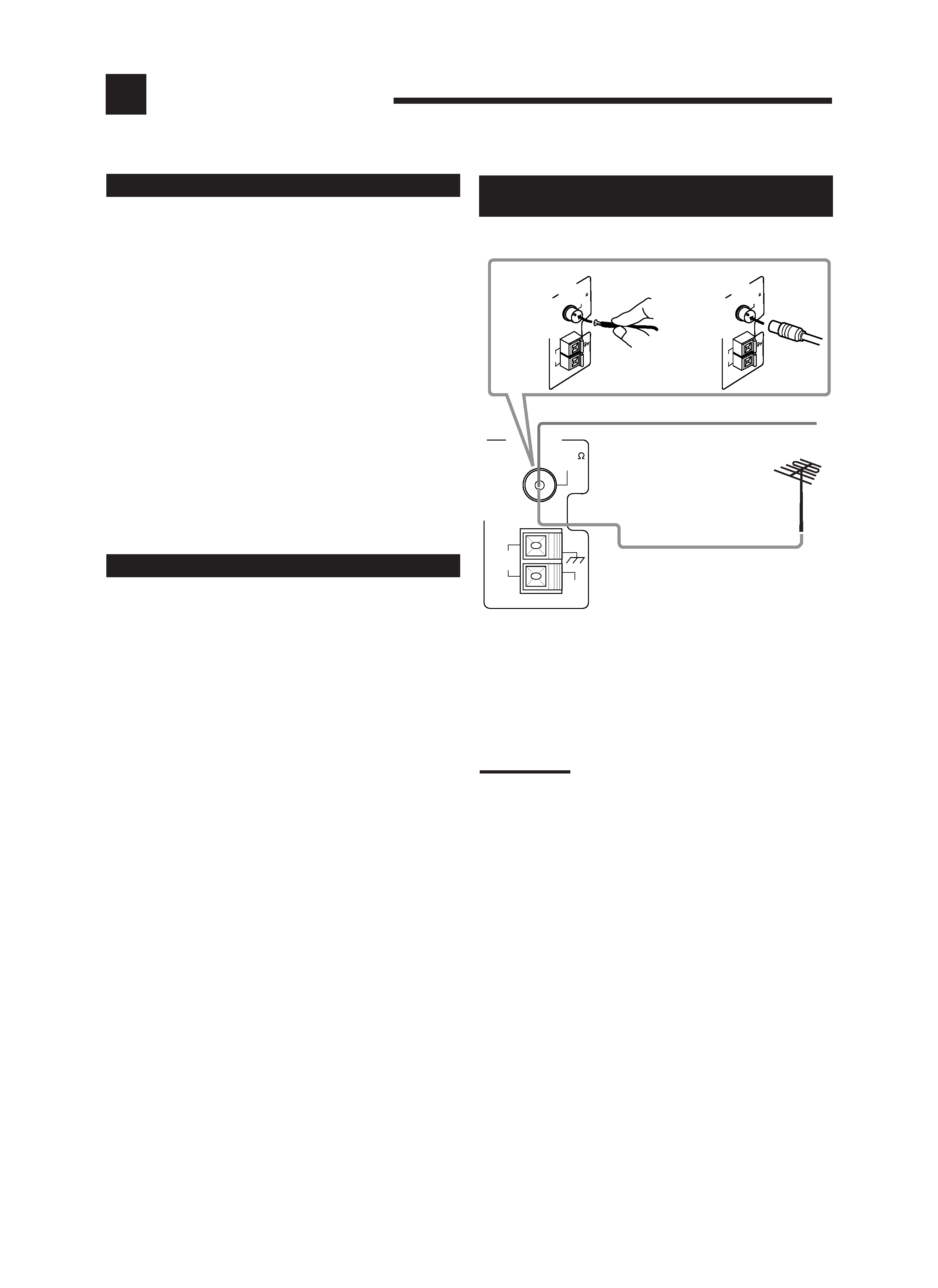
A. Using the Supplied FM Antenna
The FM antenna provided can be connected to the FM 75
COAXIAL terminal as temporary measure.
B. Using the Standard Type Connector (Not Supplied)
A standard type connector should be connected to the FM 75
COAXIAL terminal.
Note:
If reception is poor, connect the outdoor antenna.
Before attaching a 75
coaxial cable (the kind with a round wire going
to an outdoor antenna), disconnect the supplied FM antenna.
Connecting the FM and AM
Antennas
FM Antenna Connections
B
FM Antenna
Outdoor FM Antenna Cable
Extend the supplied FM antenna horizontally.
A
EN01-09.RX-7000V[J]/f
00.1.12, 11:36 AM
3