For Customer Use:
Enter below the Model No. and Serial
No. which are located either on the rear,
bottom or side of the cabinet. Retain this
information for future reference.
Model No.
Serial No.
LVT0578-005A
[B]
RX-6010RBK / RX-6012RSL
INSTRUCTIONS
AUDIO/VIDEO CONTROL RECEIVER
1
7
1
DISPLAY
REMOTE CONTROL
SURROUND
SURROUND
MODE
SOUND
TV/VIDEO
CD-DISC
1
5
SUBWOOFER +
TEST
6
5
4
EFFECT
CENTER +
5
9
8
REAR·L +
VCR CH +
5
TV
VCR
AUDIO
SLEEP
+10
10
REAR·R +
MENU
ENTER
5
TAPE/CDR
FM/AM
MUTING
CD
TV SOUND
VCR ANALOG/DIGITAL
TV VOL
TV CH
DVD
+
+
VOLUME
£
8
+
7/P
RM-SRX6010R
A/V CONTROL RECEIVER
3
2
PTY
+ PTY
PTY SEARCH
DVD
VCR
TV SOUND
ADJUST
AUDIO/VIDEO CONTROL RECEIVER
SETTING
MASTER VOLUME
CONTROL
DOWN
UP
CD
TAPE/CDR
SOURCE NAME
INPUT DIGITAL
INPUT ANALOG
SPEAKERS ON/OFF
DSP MODE
PHONES
SURROUND ON/OFF
FM/AM TUNING
STANDBY
FM/AM PRESET
FM MODE
MEMORY
INPUT ATT
FM/AM
DIGITAL
DIGITAL
SURROUND
STANDBY/ON
EON
DISPLAY MODE
PTY SEARCH
TA/NEWS/INFO
DIGITAL
RX-6010&6012R[B]COVER_f
01.1.9, 5:51 PM
1
G-1
Warnings, Cautions and Others
IMPORTANT for the U.K.
DO NOT cut off the mains plug from this equipment. If the plug
fitted is not suitable for the power points in your home or the
cable is too short to reach a power point, then obtain an
appropriate safety approved extension lead or consult your
dealer.
BE SURE to replace the fuse only with an identical approved
type, as originally fitted.
If nonetheless the mains plug is cut off ensure to remove the
fuse and dispose of the plug immediately, to avoid a possible
shock hazard by inadvertent connection to the mains supply.
If this product is not supplied fitted with a mains plug then follow
the instructions given below:
IMPORTANT.
DO NOT make any connection to the terminal which is marked
with the letter E or by the safety earth symbol or coloured green
or green-and-yellow.
The wires in the mains lead on this product are coloured in
accordance with the following code:
Blue :
Neutral
Brown :
Live
As these colours may not correspond with the coloured
markings identifying the terminals in your plug proceed as
follows:
The wire which is coloured blue must be connected to the
terminal which is marked with the letter N or coloured black.
The wire which is coloured brown must be connected to the
terminal which is marked with the letter L or coloured red.
IF IN DOUBT - CONSULT A COMPETENT ELECTRICIAN.
CAUTION
To reduce the risk of electrical shocks, fire, etc.:
1.
Do not remove screws, covers or cabinet.
2.
Do not expose this appliance to rain or moisture.
Caution
switch!
Disconnect the mains plug to shut the power off completely.
The
switch in any position does not disconnect the mains
line. The power can be remote controlled.
CAUTION
·
Do not block the ventilation openings or holes.
(If the ventilation openings or holes are blocked by a
newspaper or cloth, etc., the heat may not be able to get
out.)
·
Do not place any naked flame sources, such as lighted
candles, on the apparatus.
·
When discarding batteries, environmental problems must
be considered and local rules or laws governing the
disposal of these batteries must be followed strictly.
·
Do not use this apparatus in a bathroom or places with
water. Also do not place any containers filled with water or
liquids (such as cosmetics or medicines, flower vases,
potted plants, cups, etc.) on top of this apparatus.
RX-6010&6012R[B]SAFETY_f
01.1.9, 5:51 PM
1
G-2
SAFETY INSTRUCTIONS
"SOME DOS AND DON'TS ON THE SAFE USE OF EQUIPMENT"
This equipment has been designed and manufactured to meet international safety standards but, like any electrical equipment, care must be
taken if you are to obtain the best results and safety is to be assured.
Do read the operating instructions before you attempt to use the equipment.
Do ensure that all electrical connections (including the mains plug, extension leads and interconnections between pieces of equipment) are
properly made and in accordance with the manufacturer's instructions. Switch off and withdraw the mains plug when making or changing
connections.
Do consult your dealer if you are ever in doubt about the installation, operation or safety of your equipment.
Do be careful with glass panels or doors on equipment.
DON'T continue to operate the equipment if you are in any doubt about it working normally, or if it is damaged in any wayswitch off, withdraw
the mains plug and consult your dealer.
DON'T remove any fixed cover as this may expose dangerous voltages.
DON'T leave equipment switched on when it is unattended unless it is specifically stated that it is designed for unattended operation or has
a standby mode.
Switch off using the switch on the equipment and make sure that your family know how to do this.
Special arrangements may need to be made for infirm or handicapped people.
DON'T use equipment such as personal stereos or radios so that you are distracted from the requirements of traffic safety. It is illegal to watch
television whilst driving.
DON'T listen to headphones at high volume as such use can permanently damage your hearing.
DON'T obstruct the ventilation of the equipment, for example with curtains or soft furnishings.
Overheating will cause damage and shorten the life of the equipment.
DON'T use makeshift stands and NEVER fix legs with wood screws -- to ensure complete safety always fit the manufacturer's approved
stand or legs with the fixings provided according to the instructions.
DON'T allow electrical equipment to be exposed to rain or moisture.
ABOVE ALL
-- NEVER let anyone, especially children, push anything into holes, slots or any other opening in the case -this could result in a fatal
electrical shock.;
-- NEVER guess or take chances with electrical equipment of any kind -- it is better to be safe than sorry!
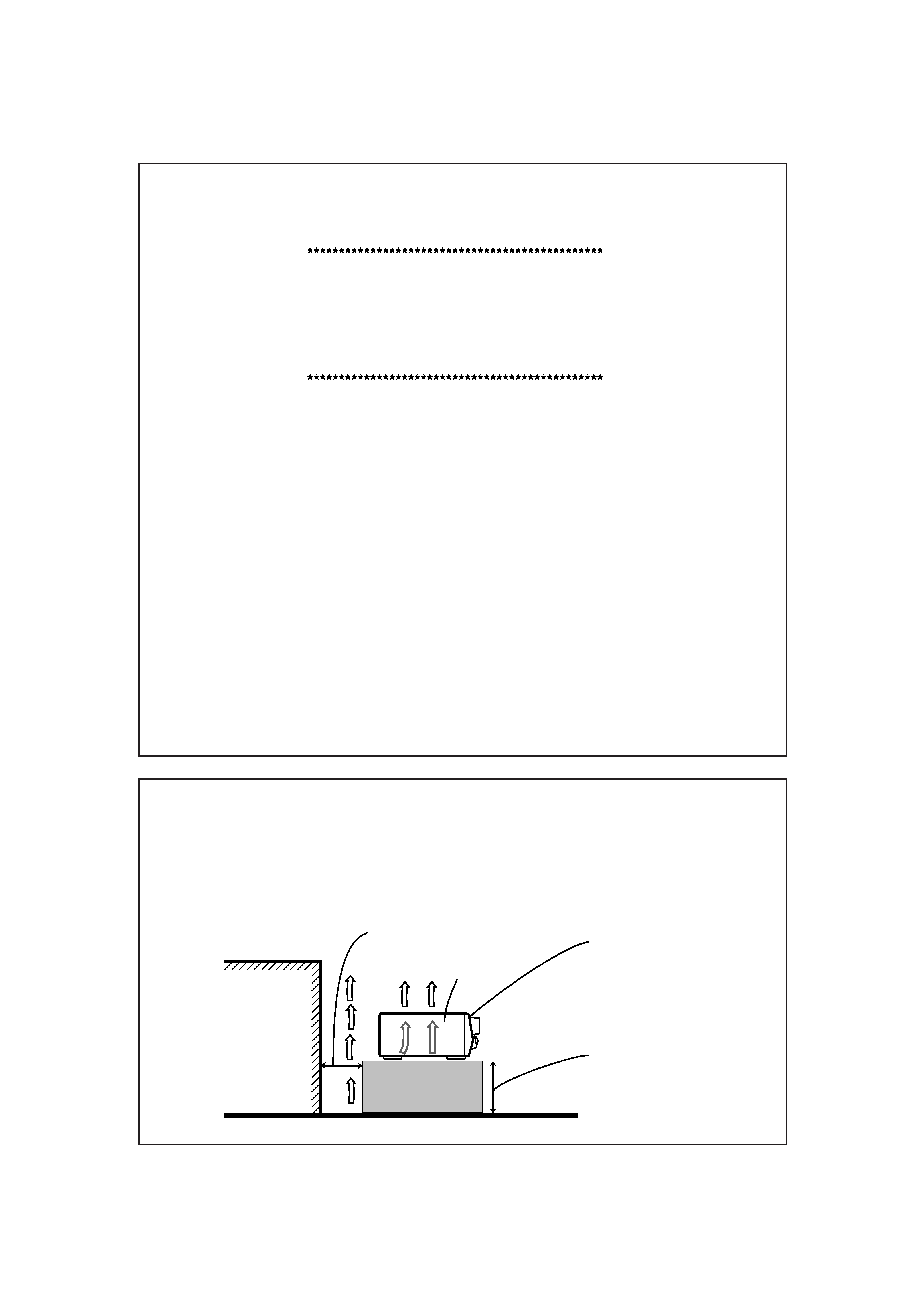
Floor
Front
Spacing 15 cm or more
Wall or obstructions
Stand height 15 cm or more
RX-6010RBK/
RX-6012RSL
Caution: Proper Ventilation
To avoid risk of electric shock and fire and to protect from damage.
Locate the apparatus as follows:
Front:
No obstructions open spacing.
Sides:
No obstructions in 10 cm from the sides.
Top:
No obstructions in 10 cm from the top.
Back:
No obstructions in 15 cm from the back
Bottom:
No obstructions, place on the level surface.
In addition, maintain the best possible air circulation as illustrated.
RX-6010&6012R[B]SAFETY_f
01.2.7, 3:09 PM
2

1
Table of Contents
Parts Identification ...................................... 2
Getting Started ........................................... 3
Before Installation ...................................................................... 3
Checking the Supplied Accessories ........................................... 3
Connecting the FM and AM (MW/LW) Antennas ..................... 3
Connecting the Speakers ............................................................ 4
Connecting Audio/Video Components ....................................... 5
Connecting the Power Cord ....................................................... 7
Putting Batteries in the Remote Control .................................... 7
Basic Operations ......................................... 8
Turning the Power On and Off (Standby) .................................. 8
Selecting the Source to Play ....................................................... 8
Adjusting the Volume ................................................................. 9
Listening Only with Headphones ............................................... 9
Muting the Sound ....................................................................... 9
Adjusting the Subwoofer Output Level .................................... 10
Attenuating the Input Signal .................................................... 10
Adjusting the Tone ................................................................... 10
Basic Settings ........................................... 11
Recording a Source .................................................................. 11
Adjusting the Front Speaker Output Balance ........................... 11
Setting the Subwoofer Information .......................................... 11
Changing the Source Name ...................................................... 11
Setting the Speakers for the DSP Modes ................................. 12
Digital Input (DIGITAL IN) Terminal Setting ......................... 14
Selecting the Analog or Digital Input Mode ............................ 14
Storing the Basic Settings and Adjustments ............................. 15
Using the Sleep Timer .............................................................. 15
Receiving Radio Broadcasts ........................ 16
Tuning in Stations Manually .................................................... 16
Using Preset Tuning ................................................................. 16
Selecting the FM Reception Mode ........................................... 17
Using the RDS (Radio Data System) to Receive FM Stations .. 18
Searching for a Program by PTY Codes .................................. 18
Switching to a Broadcast Program of
Your Choice Temporarily ................................................... 19
Using the DSP Modes ................................ 21
What are the DSP Modes? ....................................................... 21
Reproducing the Sound Field ................................................... 22
Available DSP Modes According to the Speaker Arrangement .. 23
Adjusting the Surround Modes ................................................ 24
Adjusting the DAP Modes ....................................................... 26
Activating the DSP Modes ....................................................... 27
COMPU LINK Remote Control System ......... 28
Operating JVC's Audio/Video Components ... 29
Operating Audio Components .................................................. 29
Operating Video Components .................................................. 30
Troubleshooting ......................................... 31
Specifications ............................................ 32
EN01-07.RX-6010&6012R[B]_f
01.1.18, 3:36 PM
1
2
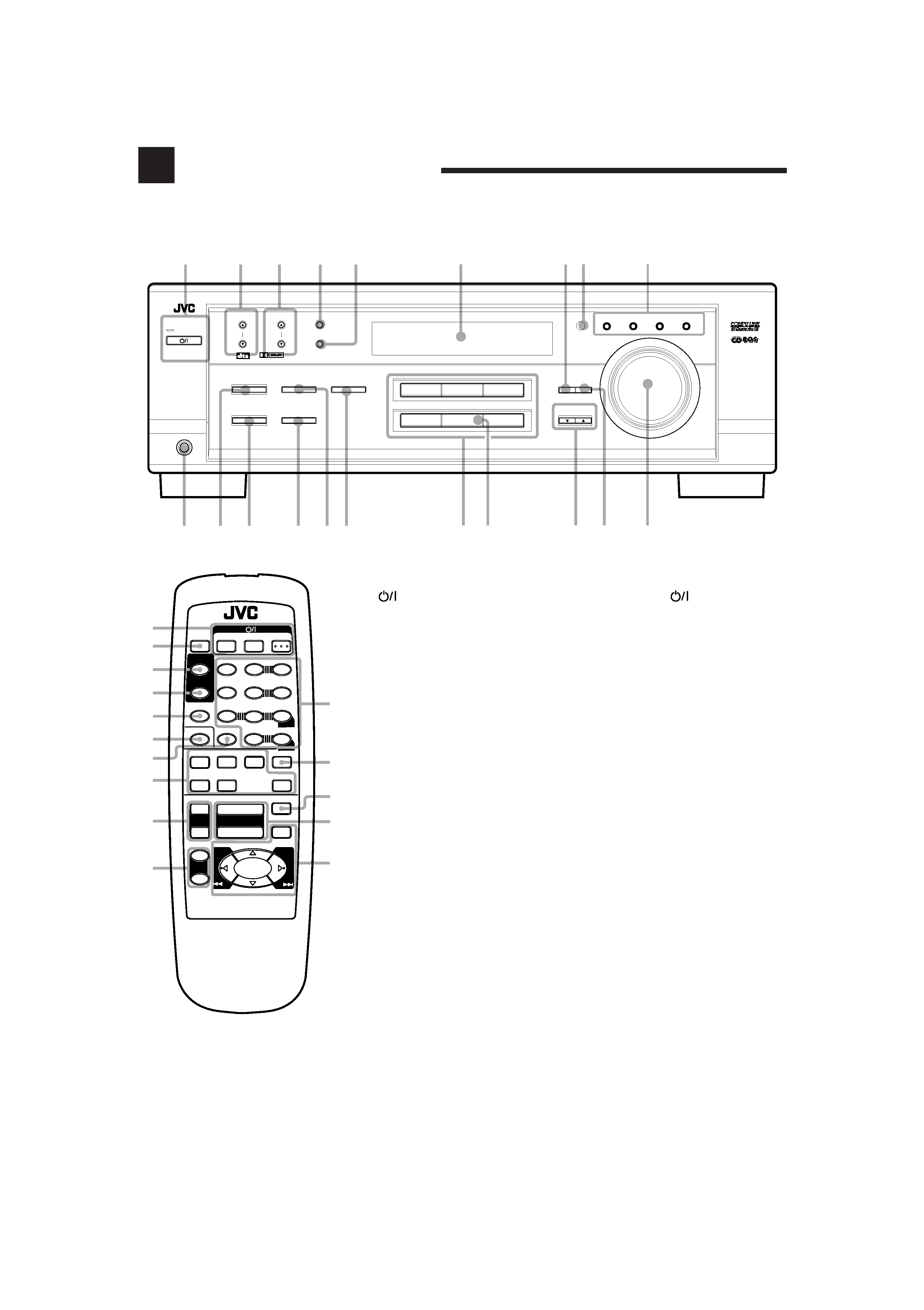
Parts Identification
Become familiar with the buttons and controls on the receiver before use.
Refer to the pages in parentheses for details.
Front Panel
1 STANDBY/ON
button and
STANDBY lamp (8)
2 FM/AM TUNING
5/ buttons (16)
3 FM/AM PRESET
5/ buttons (16, 17)
4 FM MODE button (17)
5 MEMORY button (16)
6 Display (8)
7 ADJUST button (10, 11, 24 26)
8 Remote sensor (7)
9 RDS operation buttons (18, 19)
EON, PTY SEARCH,
TA/NEWS/INFO, DISPLAY MODE
p PHONES jack (9)
q SURROUND ON/OFF button (24, 27)
w DSP MODE button (25 27)
e SPEAKERS ON/OFF button (9)
r INPUT ANALOG button (15)
INPUT ATT button (10)
t INPUT DIGITAL button (14)
y Source selecting buttons (8, 9, 14)
DVD, VCR, TV SOUND, CD,
TAPE/CDR, FM/AM
u SOURCE NAME button (11)
* TAPE/CDR button also functions as
the SOURCE NAME button.
i CONTROL UP
5/DOWN buttons
o SETTING button (11 14)
; MASTER VOLUME control (9)
Remote Control
1
(standby/on) buttons (8, 30)
TV, VCR, AUDIO
2 SLEEP button (15)
3 SURROUND button (24, 27, 29)
4 SURROUND MODE button
(25 27, 29)
5 SOUND button (10, 24 26, 29)
6 TV/VIDEO button (30)
7 CD-DISC button (30)
8 Source selecting buttons (8, 9, 15)
DVD, TV SOUND, VCR, CD,
TAPE/CDR, FM/AM
9 TV VOL +/ buttons (30)
p TV CH +/ buttons (30)
q · 10 keys for selecting preset channels
(17)
· 10 keys for adjusting sound
(24 26, 29)
· 10 keys for operating audio/video
components (29, 30)
w ANALOG/DIGITAL button (15)
e MUTING button (9)
r VOLUME +/ buttons (9)
t · RDS operation buttons (18, 19)
PTY SEARCH, PTY +/, DISPLAY
· Operating buttons for audio/video
components (29, 30)
DVD
VCR
TV SOUND
AUDIO/VIDEO CONTROL RECEIVER
MASTER VOLUME
CONTROL
DOWN
UP
CD
TAPE/CDR
SOURCE NAME
INPUT DIGITAL
INPUT ANALOG
SPEAKERS ON/OFF
DSP MODE
PHONES
SURROUND ON/OFF
FM/AM TUNING
STANDBY
FM/AM PRESET
FM MODE
MEMORY
INPUT ATT
FM/AM
DIGITAL
DIGITAL
SURROUND
12
3
4
5
6
7 8
pq
e
wr ty
i
9
o
ADJUST
SETTING
STANDBY/ON
EON
DISPLAY MODE
PTY SEARCH
TA/NEWS/INFO
;
u
1
REMOTE CONTROL
SURROUND
SURROUND
MODE
SOUND
TV/VIDEO
CD-DISC
1
5
SUBWOOFER +
TEST
6
5
4
EFFECT
CENTER +
5
9
8
REAR·L +
VCR CH +
5
SLEEP
REAR·R +
MENU
5
TAPE/CDR
FM/AM
MUTING
CD
TV SOUND
VCR
TV VOL
TV CH
DVD
+
+
VOLUME
1
3
4
5
6
7
8
9
w
q
r
t
2
p
7/P
RM-SRX6010R
A/V CONTROL RECEIVER
3
2
ANALOG/DIGITAL
ENTER
+10
10
+
+
7
TV
VCR
AUDIO
e
DISPLAY
+ PTY
8
£ PTY SEARCH
PTY
1
EN01-07.RX-6010&6012R[B]_f
01.1.18, 3:36 PM
2