LVT1140-001A
[J]
RX-6040B/RX-6042S
RX-5040B/RX-5042S/RX-5045B
AUDIO/VIDEO CONTROL RECEIVER
INSTRUCTIONS
For Customer Use:
Enter below the Model No. and Serial
No. which are located either on the rear,
bottom or side of the cabinet. Retain this
information for future reference.
Model No.
Serial No.
TA/NEWS/INFO
DISPLAY MODE
Cover_RX-60_5040[J]f.p65
03.12.18, 15:19
3
G-1
CAUTION
To reduce the risk of electrical shocks, fire, etc.:
1. Do not remove screws, covers or cabinet.
2. Do not expose this appliance to rain or moisture.
ATTENTION
Afin d'éviter tout risque d'électrocution, d'incendie, etc.:
1. Ne pas enlever les vis ni les panneaux et ne pas ouvrir
le coffret de l'appareil.
2. Ne pas exposer l'appareil à la pluie ni à l'humidité.
Warnings, Cautions and Others/
Mises en garde, précautions et indications diverses
CautionSTANDBY/ON
button!
Disconnect the mains plug to shut the power off completely.
The STANDBY/ON
button in any position does not
disconnect the mains line. The power can be remote controlled.
AttentionCommutateur STANDBY/ON
!
Déconnecter la fiche de secteur pour couper complètement le
courant. Le commutateur STANDBY/ON
ne coupe jamais
complètement la ligne de secteur, quelle que soit sa position.
Le courant peut être télécommandé.
Note to CATV system installer:
This reminder is provided to call the CATV system installer's
attention to Section 820-40 of the NEC which provides
guidelines for proper grounding and, in particular, specifies
that the cable ground shall be connected to the grounding
system of the building, as close to the point of cable entry as
practical.
For Canada/pour le Canada
THIS DIGITAL APPARATUS DOES NOT EXCEED THE
CLASS B LIMITS FOR RADIO NOISE EMISSIONS FROM
DIGITAL APPARATUS AS SET OUT IN THE INTERFER-
ENCE-CAUSING EQUIPMENT STANDARD ENTITLED
"DIGITAL APPARATUS," ICES-003 OF THE DEPARTMENT
OF COMMUNICATIONS.
CET APPAREIL NUMERIQUE RESPECTE LES LIMITES
DE BRUITS RADIOELECTRIQUES APPLICABLES AUX
APPAREILS NUMERIQUES DE CLASSE B PRESCRITES
DANS LA NORME SUR LE MATERIEL BROUILLEUR;
"APPAREILS NUMERIQUES", NMB-003 EDICTEE PAR LE
MINISTRE DES COMMUNICATIONS.
CAUTION:
TO REDUCE THE RISK OF ELECTRIC SHOCK.
DO NOT REMOVE COVER (OR BACK)
NO USER SERVICEABLE PARTS INSIDE.
REFER SERVICING TO QUALIFIED SERVICE PERSONNEL.
RISK OF ELECTRIC SHOCK
DO NOT OPEN
The lightning flash with arrowhead symbol,
within an equilateral triangle is intended to
alert the user to the presence of uninsulated
"dangerous voltage" within the product's
enclosure
that
may
be
of
sufficient
magnitude to constitute a risk of electric
shock to persons.
The exclamation point within an equilateral
triangle is intended to alert the user to the
presence
of
important
operating
and
maintenance (servicing) instructions in the
literature accompanying the appliance.
CAUTION
CAUTION: TO PREVENT ELECTRIC SHOCK, MATCH WIDE
BLADE OF PLUG TO WIDE SLOT, FULLY INSERT.
ATTENTION: POUR EVITER LES CHOCS ELECTRIQUES,
INTRODUIRE LA LAME LA PLUS LARGE DE LA FICHE DANS LA
BORNE CORRESPONDANTE DE LA PRISE ET POUSSER
JUSQUAU FOND.
For U.S.A
This equipment has been tested and found to comply with the limits
for a Class B digital device, pursuant to part 15 of the FCC Rules.
These limits are designed to provide reasonable protection against
harmful interference in a residential installation.
This equipment generates, uses and can radiate radio frequency
energy and, if not installed and used in accordance with the
instructions,
may
cause
harmful
interference
to
radio
communications. However, there is no guarantee that interference
will not occur in a particular installation. If this equipment does cause
harmful interference to radio or television reception, which can be
determined by turning the equipment off and on, the user is
encouraged to try to correct the interference by one or more of the
following measures:
Reorient or relocate the receiving antenna.
Increase the separation between the equipment and receiver.
Connect the equipment into an outlet on a circuit different from that
to which the receiver is connected.
Consult the dealer or an experienced radio/TV technician for help.
WARNING: TO REDUCE THE RISK OF FIRE
OR ELECTRIC SHOCK, DO NOT EXPOSE
THIS APPLIANCE TO RAIN OR MOISTURE.
Safety_RX_60_5040[J]f.p65
03.12.18, 15:28
1

1
Table of Contents
Adjusting Sound ........................................ 23
Basic Adjustment Items ............................................................ 23
Basic Procedure ........................................................................ 23
7 Adjusting the Equalization Patterns ..................................... 24
7 Adjusting the Speaker Output Levels ................................... 24
7 Adjusting the Sound Parameters for the Surround
and DSP Modes .................................................................... 24
Using the Surround Modes .......................... 25
Reproducing Theater Ambience ................................................ 25
Introducing the Surround Modes ............................................. 25
Activating the Surround Modes ............................................... 27
Using the DSP Modes ................................ 28
Reproducing the Sound Field ................................................... 28
Introducing the DSP Modes ..................................................... 28
Activating the DSP Modes ....................................................... 29
COMPU LINK Remote Control System ......... 30
AV COMPU LINK Remote Control System .... 31
Operating JVC's Audio/Video Components ... 33
Operating Audio Components .................................................. 33
Operating Video Components .................................................. 34
Operating Other Manufacturers' Video
Equipment ............................................ 35
Troubleshooting ......................................... 37
Specifications ............................................ 38
Parts Identification ...................................... 2
Getting Started ........................................... 5
Before Installation ...................................................................... 5
Checking the Supplied Accessories ........................................... 5
Putting Batteries in the Remote Control .................................... 5
Connecting the FM and AM Antennas ....................................... 5
Connecting the Speakers and Subwoofer ................................... 6
Connecting Audio/Video Components ....................................... 7
7 Analog Connections ............................................................... 7
7 Digital Connections .............................................................. 10
Connecting the Power Cord ..................................................... 10
Basic Operations ....................................... 11
Daily Operational Procedure .................................................... 11
Turning On the Power .............................................................. 11
Selecting the Source to Play ..................................................... 11
Adjusting the Volume ............................................................... 12
Turning On and Off the Subwoofer Sound .............................. 13
Selecting the Analog or Digital Input Mode ............................ 13
Changing the Display Brightness ............................................. 14
Attenuating the Input Signal .................................................... 14
Changing the Source Name ...................................................... 14
Reinforcing the Bass ................................................................ 15
Muting the Sound ..................................................................... 15
Using the Sleep Timer .............................................................. 15
Receiving Radio Broadcasts ........................ 16
Tuning in to Stations Manually ................................................ 16
Using Preset Tuning ................................................................. 16
Selecting the FM Reception Mode ........................................... 17
Basic Settings ........................................... 18
Quick Speaker Setup ................................................................ 18
Basic Setting Items ................................................................... 19
Basic Procedure ........................................................................ 19
7 Setting the Speakers ............................................................. 20
7 Setting the Speaker Distance ................................................ 20
7 Setting the Bass Sounds ....................................................... 20
7 Selecting the Main or Sub Channel ...................................... 21
7 Setting for Easy and Effective Surround Operations ............ 21
7 Setting the Digital Input Terminals ...................................... 22
7 Setting the Component Video Input ..................................... 22
This mark indicates that ONLY the remote control
CAN be used for the operation explained.
Remote
NOT
This mark indicates that the remote control
CANNOT be used for the operation explained.
Use the buttons and controls on the front panel.
01-10_5040&6040[J]f.p65
03.12.18, 15:20
1
2
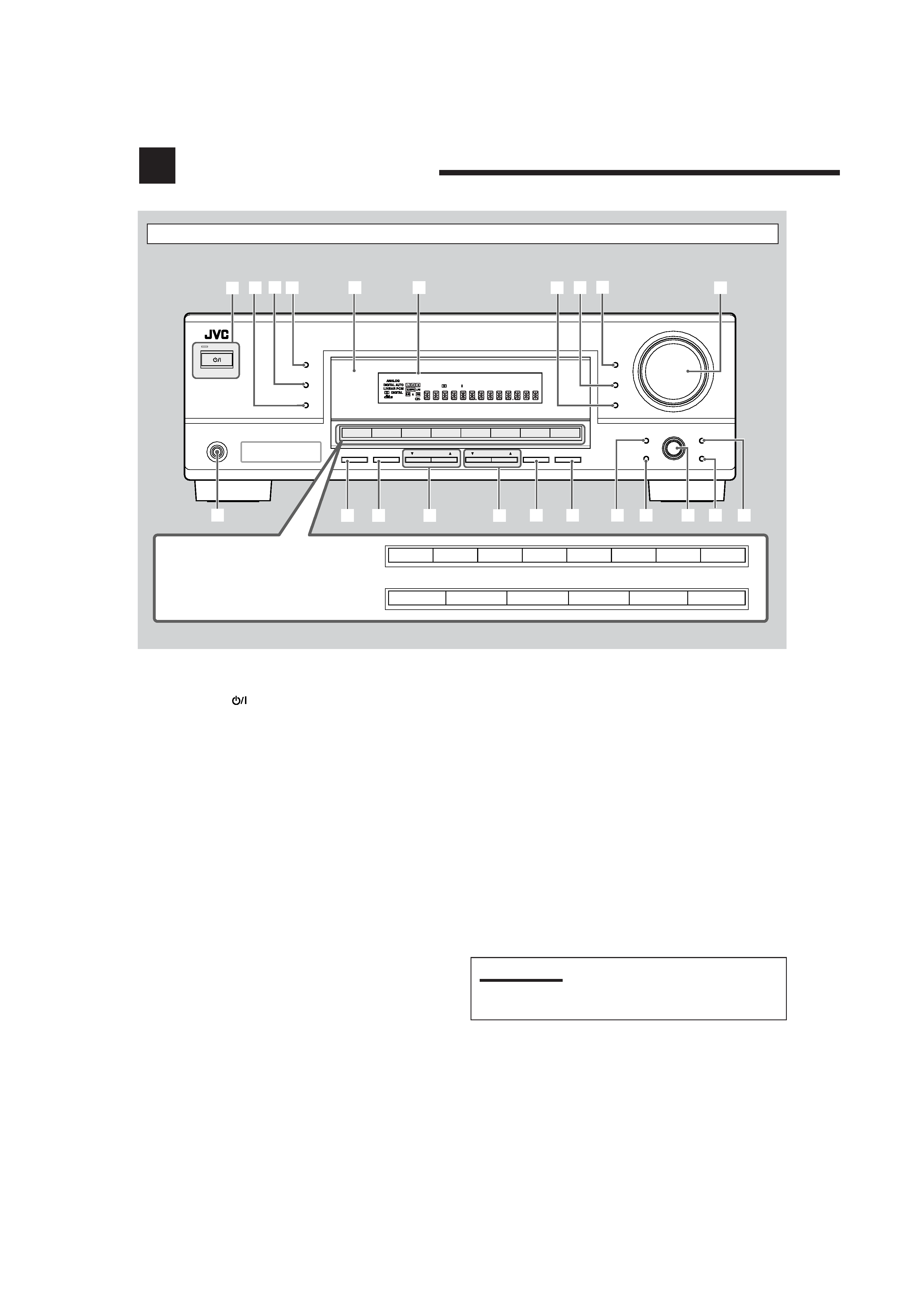
Front Panel
Parts Identification
DIGITAL
PRO LOGIC
STANDBY
STANDBY/ON
PHONES
SURROUND
DSP
SPEAKERS
ON/OFF
SUBWOOFER OUT
FM MODE
MEMORY
ON/OFF
FM/AM TUNING
SURROUND/DSP
OFF
DIMMER
MASTER VOLUME
INPUT DIGITAL
RX6030V
AUDIO/VIDEO CONTROL RECEIVER
SETTING
MULTI JOG
PUSH SET
QUICK SPEAKER
SETUP
ADJUST
EXIT
INPUT ANALOG
INPUT ATT
FM/AM PRESET
3D - PHONIC
DUAL MONO
H.PHONE
SB
DSP DIGITAL EQ BASS BOOST
INPUT ATT VOLUME
PROLOGIC
VIRTUAL SB
TUNED STEREO AUTO MUTING SLEEP
96/24
1 2 3 4
5
q
w
e
y
u
io
as
RX-6040B/RX-6042S
RX-5040B/RX-5042S/RX-5045B
r
t
DVD MULTI
DVD
DVD
VCR
VCR
CD
CD
FM
FM/AM
AM
TAPE/CDR
TAPE/CDR
TV SOUND
TV SOUND
SOURCE NAME
6
7 8 9
p
SOURCE NAME
;
d
See pages in parentheses for details.
1 STANDBY/ON
button and STANDBY lamp (11)
2 SURROUND/DSP OFF button (27, 29)
3 DSP button (28, 29)
4 SURROUND button (27)
5 Remote sensor
6 Display (For details, see "Display" on the next page.)
7 INPUT ANALOG button (14)
INPUT ATT button (14)
8 INPUT DIGITAL button (13)
9 DIMMER button (14)
p MASTER VOLUME control (12)
q PHONES jack (13)
w SPEAKERS ON/OFF button (13)
e SUBWOOFER OUT ON/OFF button (13)
r FM/AM TUNING
5/ buttons (16)
t FM/AM PRESET
5/ buttons (16)
y FM MODE button (17)
u MEMORY button (16)
i SETTING button (19)
o QUICK SPEAKER SETUP button (18)
; MULTI JOG (PUSH SET) dial (19, 23)
a EXIT button (19, 23)
s ADJUST button (23)
d Source selection buttons (11 ,14)
· For RX-6040B/RX-6042S: DVD MULTI, DVD, VCR,
TV SOUND, CD, TAPE/CDR (SOURCE NAME), FM, AM
· For RX-5040B/RX-5042S/RX-5045B: DVD, VCR,
TV SOUND, CD, TAPE/CDR (SOURCE NAME), FM/AM
IMPORTANT:
Illustrations used in this manual are of RX-6040B/RX-6042S
unless mentioned otherwise.
01-10_5040&6040[J]f.p65
03.12.18, 15:20
2
3
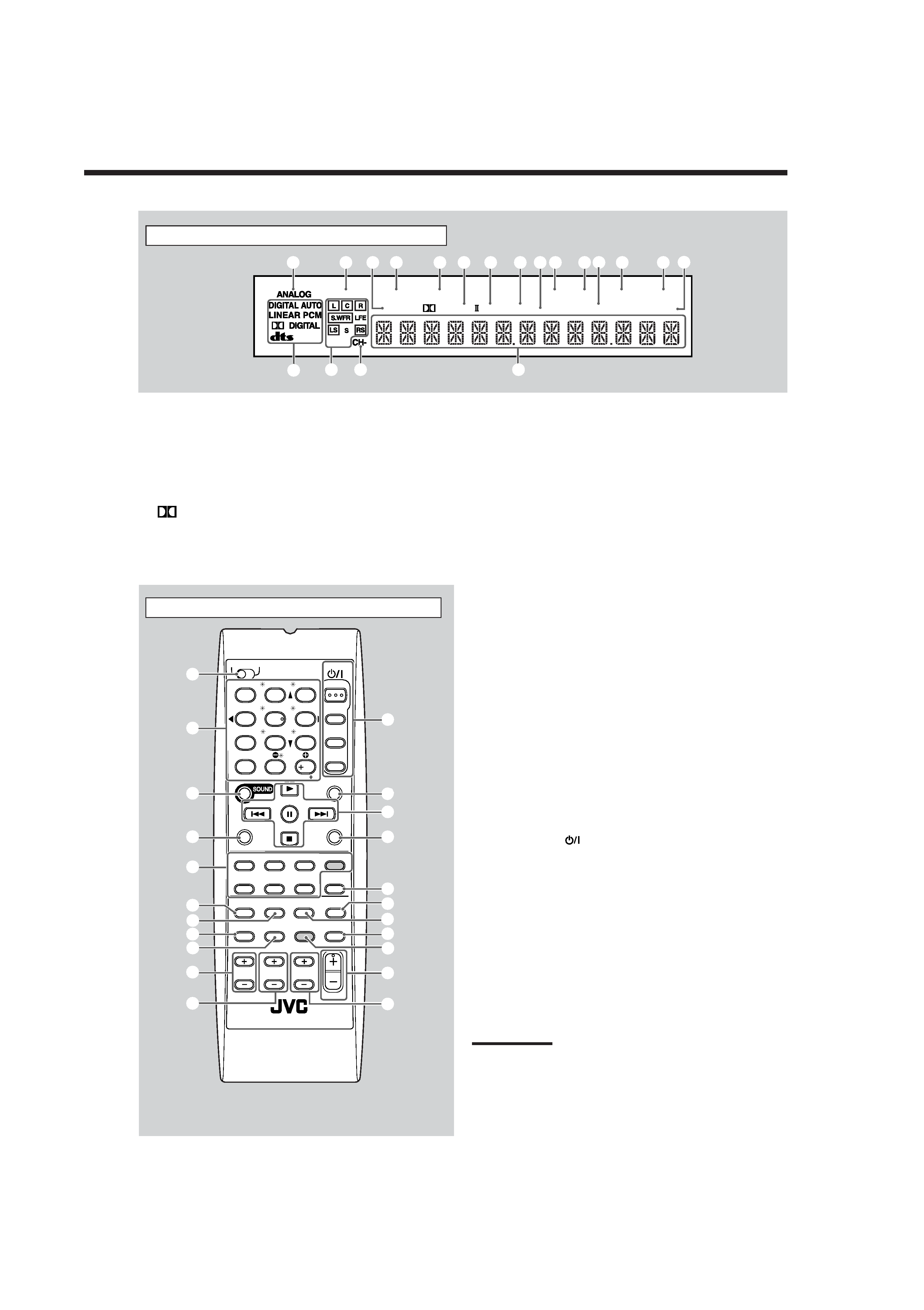
Remote Control
Remote Control
See pages in parentheses for details.
1 TV/CATV selector (35)
2 10 keys for selecting preset channels (17, 33)
10 keys for sound adjustment (24, 33)
10 keys for operating audio/video components (33 35)
3 SOUND button (24, 33)
4 REC PAUSE button (34, 36)
5 Source selection buttons (11, 12)
TAPE/CDR, CD, DVD, DVD MULTI (only for RX-6040B/
RX-6042S), FM/AM, TV SOUND, VCR
6 FM MODE button (17, 33)
7 SURROUND button (27, 33)
8 DIMMER button (14, 33)
9 TV/VIDEO button (34, 35)
0 VCR CH +/ buttons (34, 36)
- TV/CATV CH +/ buttons (34, 35)
= STANDBY/ON
buttons (11, 33 36)
AUDIO, TV/CATV, VCR, DVD
~ SLEEP button (15, 33)
! Operating buttons for audio/video components
3, 8, 7, ¢/4, FF/REW (33, 34, 36)
@ CD-DISC button (33)
# ANALOG/DIGITAL button (13, 14, 33)
$ SURROUND/DSP OFF button (27, 29, 33)
% DSP button (28, 29, 33)
^ MUTING button (15, 33)
& Only for RX-6040B/RX-6042S: BASSBOOST button (15, 33)
* VOLUME +/ button (12, 33)
( TV VOLUME +/ buttons (34, 35)
Note:
When you press the one of the audio source selection buttons--
TAPE/CDR, CD, and FM/AM--on the remote control, the receiver
automatically turns on.
See pages in parentheses for details.
1 ANALOG indicator (14)
2 DUAL MONO indicator (26, 27)
3 H.PHONE indicator (13, 26, 28)
4 3D-PHONIC indicator (26, 28)
5 VIRTUAL SB indicator (22)
6
PRO LOGIC II indicator (25, 27, 28)
7 DSP indicator (28, 29)
8 DIGITAL EQ indicator (24)
9 Only for RX-6040B/RX-6042S: BASS BOOST indicator (15)
0 TUNED indicator (16)
- STEREO indicator (16)
= INPUT ATT indicator (14)
~ AUTO MUTING indicator (17)
! SLEEP indicator (15)
@ VOLUME indicator (11)
# Digital signal format indicators (13)
$ Speaker indicators and signal indicators (12)
% CH indicator (16)
^ Main display
Display
The buttons shaded in the illustration--DVD MULTI and
BASSBOOST--are only for RX-6040B/RX-6042S.
3D - PHONIC
DUAL MONO
H.PHONE
SB
DSP DIGITAL EQ BASS BOOST
INPUT ATT VOLUME
PROLOGIC
VIRTUAL SB
TUNED STEREO AUTO MUTING SLEEP
96/24
=
%^
@
#
13
24
5 6
7
8 9 0
-
~
!
$
AUDIO
TV/CATV
VCR
DVD
TEST
EFFECT
MENU
ENTER
LEVEL
RETURN
SURROUND
/DSP
CD-DISC
SLEEP
REC PAUSE
FM MODE SURROUND
DSP
DIMMER
TV/VIDEO BASSBOOST MUTING
OFF
VCR CH
TV/CATV CH
VOLUME
SURR R
SURR L
SUBWFR
CENTER
FRONT R
FRONT L
100
1
4
7/P
10
2
5
8
0
3
6
9
10
REW
FF
TV VOLUME
STANDBY/ON
TV
CATV
TA/NEWS/INFO
A/V CONTROL
RECEIVER
TAPE/CDR
CD
DVD
DVD MULTI
FM/AM
TV SOUND
VCR
ANALOG
/DIGITAL
2
5
=
~
$
%
#
&
@
^
4
3
1
8
7
0
-
(
*
6
9
!
01-10_5040&6040[J]f.p65
03.12.18, 15:20
3