LVT1140-003A
[UJ]
AUDIO/VIDEO CONTROL RECEIVER
INSTRUCTIONS
RX-5040B
TA/NEWS/INFO
DISPLAY MODE
Cover_5040B[UJ]1.p65
04.4.15, 2:30 PM
3
G-1
CautionSTANDBY/ON
button!
Disconnect the mains plug to shut the power off completely. The
STANDBY/ON
button in any position does not disconnect the
mains line. The power can be remote controlled.
Warnings, Cautions, and Others
CAUTION
·
Do not block the ventilation openings or holes.
(If the ventilation openings or holes are blocked by a
newspaper or cloth, etc., the heat may not be able to
get out.)
·
Do not place any naked flame sources, such as
lighted candles, on the apparatus.
·
When discarding batteries, environmental problems
must be considered and local rules or laws governing
the disposal of these batteries must be followed strictly.
·
Do not expose this apparatus to rain, moisture,
dripping or splashing and that no objects filled with
liquids, such as vases, shall be placed on the
apparatus.
CAUTION
To reduce the risk of electrical shocks, fire, etc.:
1.
Do not remove screws, covers or cabinet.
2.
Do not expose this appliance to rain or moisture.
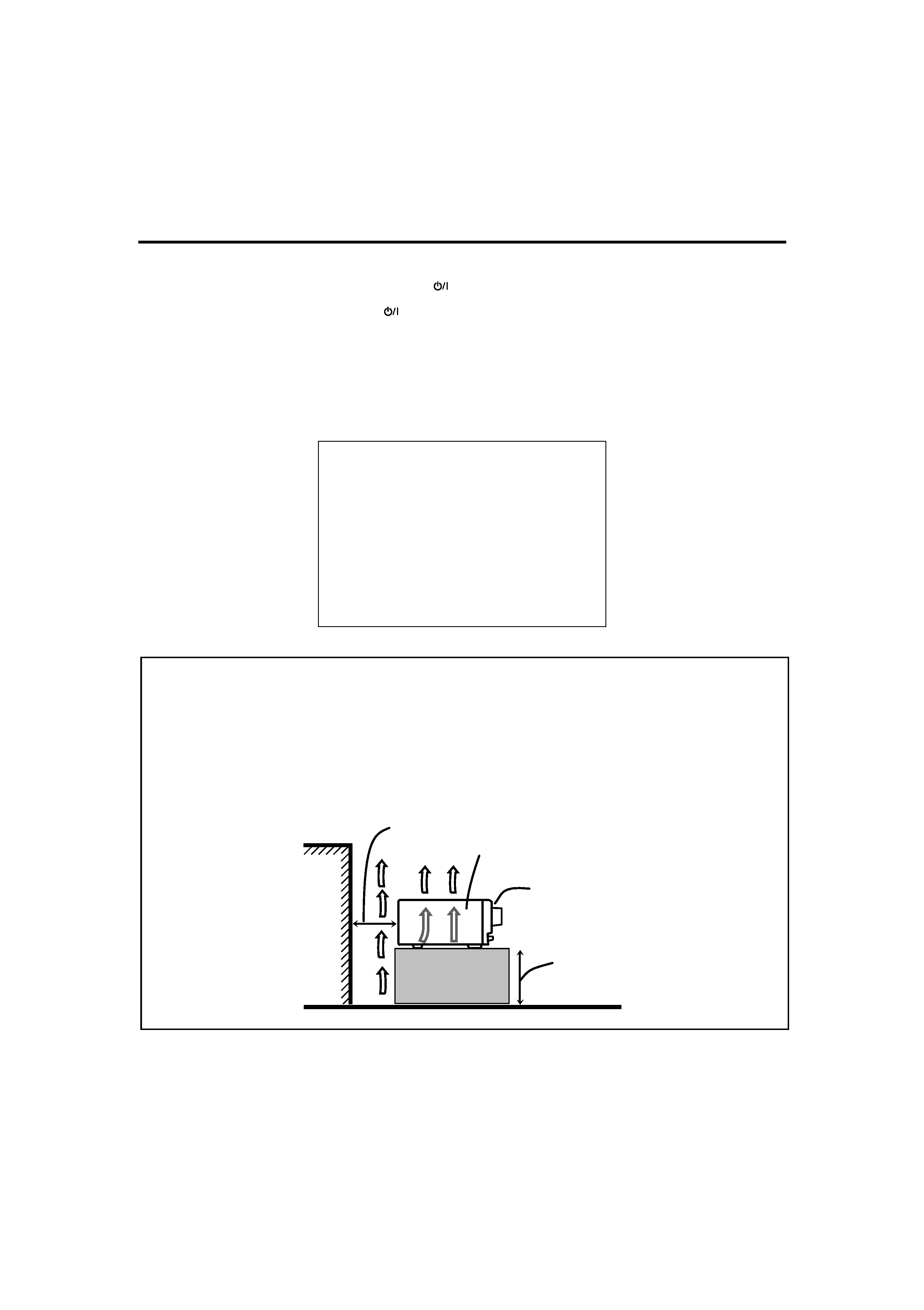
Caution: Proper Ventilation
To avoid risk of electric shock and fire and to protect from damage.
Locate the apparatus as follows:
Front:
No obstructions open spacing.
Sides:
No obstructions in 10 cm from the sides.
Top:
No obstructions in 10 cm from the top.
Back:
No obstructions in 15 cm from the back.
Bottom:
No obstructions, place on the level surface.
In addition, maintain the best possible air circulation as illustrated.
Wall or obstructions
Front
Stand height 15 cm or more
RX-5040B
Spacing 15 cm or more
Floor
Safety_RX-5040B[UJ]1.p65
04.4.15, 2:30 PM
1

1
Table of Contents
Adjusting Sound ........................................ 21
Basic Adjustment Items ............................................................ 21
Basic Procedure ........................................................................ 21
7 Adjusting the Equalization Patterns ..................................... 22
7 Adjusting the Speaker Output Levels ................................... 22
7 Adjusting the Sound Parameters for the Surround
and DSP Modes .................................................................... 22
Using the Surround Modes .......................... 23
Reproducing Theater Ambience ................................................ 23
Introducing the Surround Modes ............................................. 23
Activating the Surround Modes ............................................... 25
Using the DSP Modes ................................ 26
Reproducing the Sound Field ................................................... 26
Introducing the DSP Modes ..................................................... 26
Activating the DSP Modes ....................................................... 27
COMPU LINK Remote Control System ......... 28
AV COMPU LINK Remote Control System .... 29
Operating JVC's Audio/Video Components ... 31
Operating Audio Components .................................................. 31
Operating Video Components .................................................. 32
Operating Other Manufacturers' Video
Equipment ............................................ 33
Troubleshooting ......................................... 35
Specifications ............................................ 36
Parts Identification ...................................... 2
Getting Started ........................................... 4
Before Installation ...................................................................... 4
Checking the Supplied Accessories ........................................... 4
Putting Batteries in the Remote Control .................................... 4
Connecting the FM and AM Antennas ....................................... 4
Connecting the Speakers and Subwoofer ................................... 5
Connecting Audio/Video Components ....................................... 6
7 Analog Connections ............................................................... 6
7 Digital Connections ................................................................ 8
Adjusting the Voltage Selector ................................................... 8
Connecting the Power Cord ....................................................... 8
Basic Operations ......................................... 9
Daily Operational Procedure ...................................................... 9
Turning On the Power ................................................................ 9
Selecting the Source to Play ....................................................... 9
Adjusting the Volume ............................................................... 10
Turning On and Off the Subwoofer Sound .............................. 11
Selecting the Analog or Digital Input Mode ............................ 11
Changing the Display Brightness ............................................. 12
Attenuating the Input Signal .................................................... 12
Changing the Source Name ...................................................... 12
Muting the Sound ..................................................................... 13
Using the Sleep Timer .............................................................. 13
Receiving Radio Broadcasts ........................ 14
Setting the AM Tuner Interval Spacing .................................... 14
Tuning in to Stations Manually ................................................ 14
Using Preset Tuning ................................................................. 14
Selecting the FM Reception Mode ........................................... 15
Basic Settings ........................................... 16
Quick Speaker Setup ................................................................ 16
Basic Setting Items ................................................................... 17
Basic Procedure ........................................................................ 17
7 Setting the Speakers ............................................................. 18
7 Setting the Speaker Distance ................................................ 18
7 Setting the Bass Sounds ....................................................... 18
7 Selecting the Main or Sub Channel ...................................... 19
7 Setting for Easy and Effective Surround Operations ............ 20
7 Setting the Digital Input Terminals ...................................... 20
This mark indicates that ONLY the remote control
CAN be used for the operation explained.
Remote
NOT
This mark indicates that the remote control
CANNOT be used for the operation explained.
Use the buttons and controls on the front panel.
01-08_5040B[UJ].p65
04.4.15, 2:30 PM
1
2
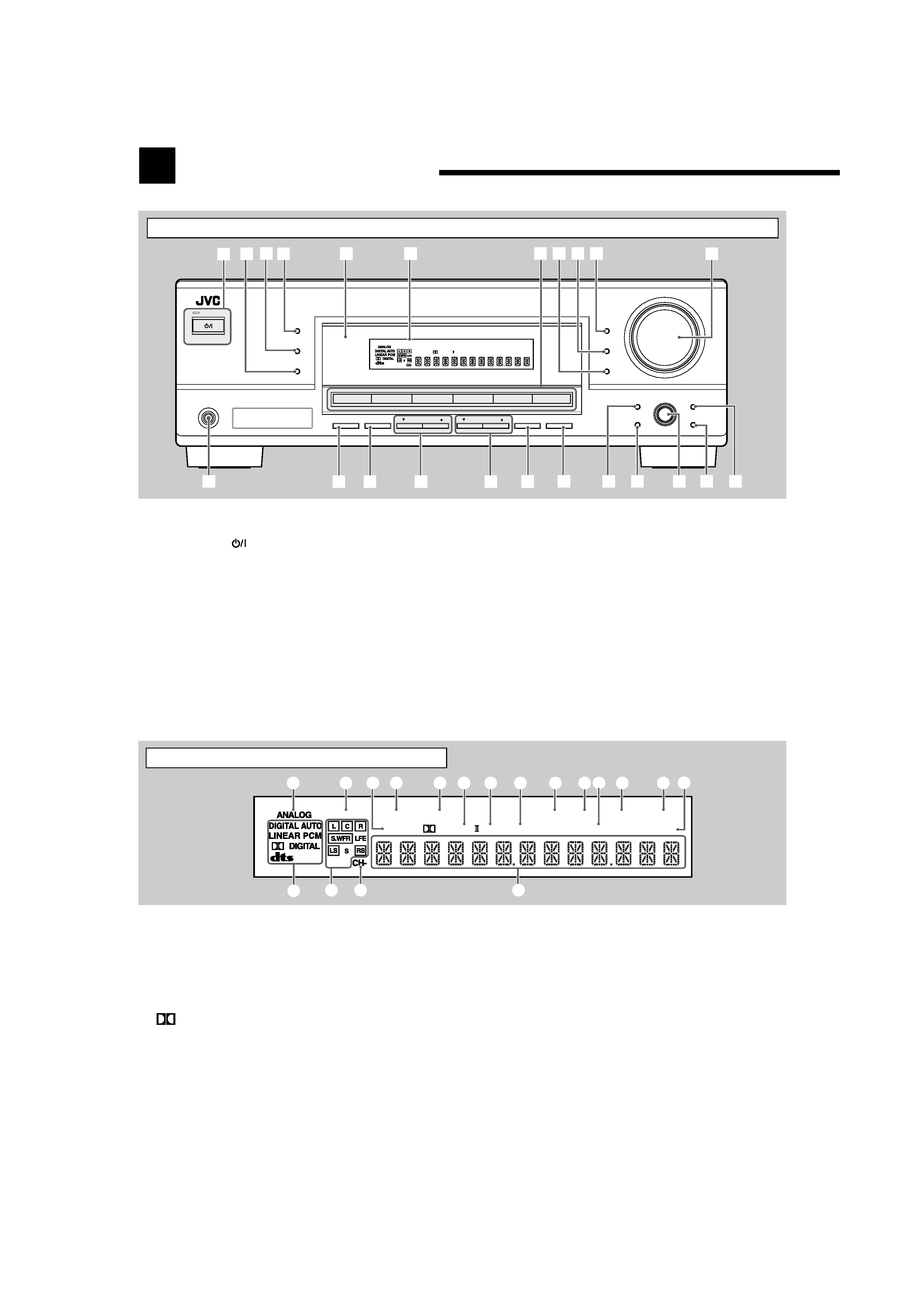
See pages in parentheses for details.
1 ANALOG indicator (12)
2 DUAL MONO indicator (24, 25)
3 H.PHONE indicator (11, 24, 26)
4 3D-PHONIC indicator (24, 26)
5 VIRTUAL SB indicator (20)
6
PRO LOGIC II indicator (23, 25, 26)
7 DSP indicator (26, 27)
8 DIGITAL EQ indicator (22)
9 TUNED indicator (14)
0 STEREO indicator (14)
- INPUT ATT indicator (12)
= AUTO MUTING indicator (15)
~ SLEEP indicator (13)
! VOLUME indicator (9)
@ Digital signal format indicators (11)
# Speaker indicators and signal indicators (10)
$ CH indicator (14)
% Main display
Front Panel
Parts Identification
DIGITAL
PRO LOGIC
STANDBY
STANDBY/ON
PHONES
SURROUND
DSP
SPEAKERS
ON/OFF
SUBWOOFER OUT
FM MODE
MEMORY
ON/OFF
FM/AM TUNING
SURROUND/DSP
OFF
DIMMER
MASTER VOLUME
INPUT DIGITAL
RX6030V
AUDIO/VIDEO CONTROL RECEIVER
SETTING
MULTI JOG
PUSH SET
QUICK SPEAKER
SETUP
ADJUST
EXIT
INPUT ANALOG
INPUT ATT
FM/AM PRESET
DVD
VCR
CD
FM/AM
TAPE/CDR
TV SOUND
SOURCE NAME
3D - PHONIC
DUAL MONO
H.PHONE
SB
DSP DIGITAL EQ
INPUT ATT VOLUME
PRO LOGIC
VIRTUAL SB
TUNED STEREO AUTO MUTING SLEEP
96/24
1 2 3 4
5
w
e
r
u
i
o;
s
d
t
y
6
7 8 9 p
q
a
See pages in parentheses for details.
1 STANDBY/ON
button and STANDBY lamp (9, 14)
2 SURROUND/DSP OFF button (25, 27)
3 DSP button (26, 27)
4 SURROUND button (25)
5 Remote sensor
6 Display (For details, see "Display" below.)
7 Source selection buttons (9, 12)
DVD, VCR, TV SOUND, CD, TAPE/CDR (SOURCE
NAME), FM/AM
8 INPUT ANALOG button (12)
INPUT ATT button (12)
9 INPUT DIGITAL button (11)
Display
3D - PHONIC
DUAL MONO
H.PHONE
SB
DSP DIGITAL EQ
INPUT ATT VOLUME
PROLOGIC
VIRTUAL SB
TUNED STEREO AUTO MUTING SLEEP
96/24
-
$%
!
@
13
24
5 6
7
8
9
0
=
~
#
p DIMMER button (12)
q MASTER VOLUME control (10)
w PHONES jack (11)
e SPEAKERS ON/OFF button (11)
r SUBWOOFER OUT ON/OFF button (11)
t FM/AM TUNING
5/ buttons (14)
y FM/AM PRESET
5/ buttons (14)
u FM MODE button (15)
i MEMORY button (14)
o SETTING button (17)
; QUICK SPEAKER SETUP button (16)
a MULTI JOG (PUSH SET) dial (17, 21)
s EXIT button (17, 21)
d ADJUST button (21)
01-08_5040B[UJ].p65
04.4.15, 2:30 PM
2
3
Remote Control
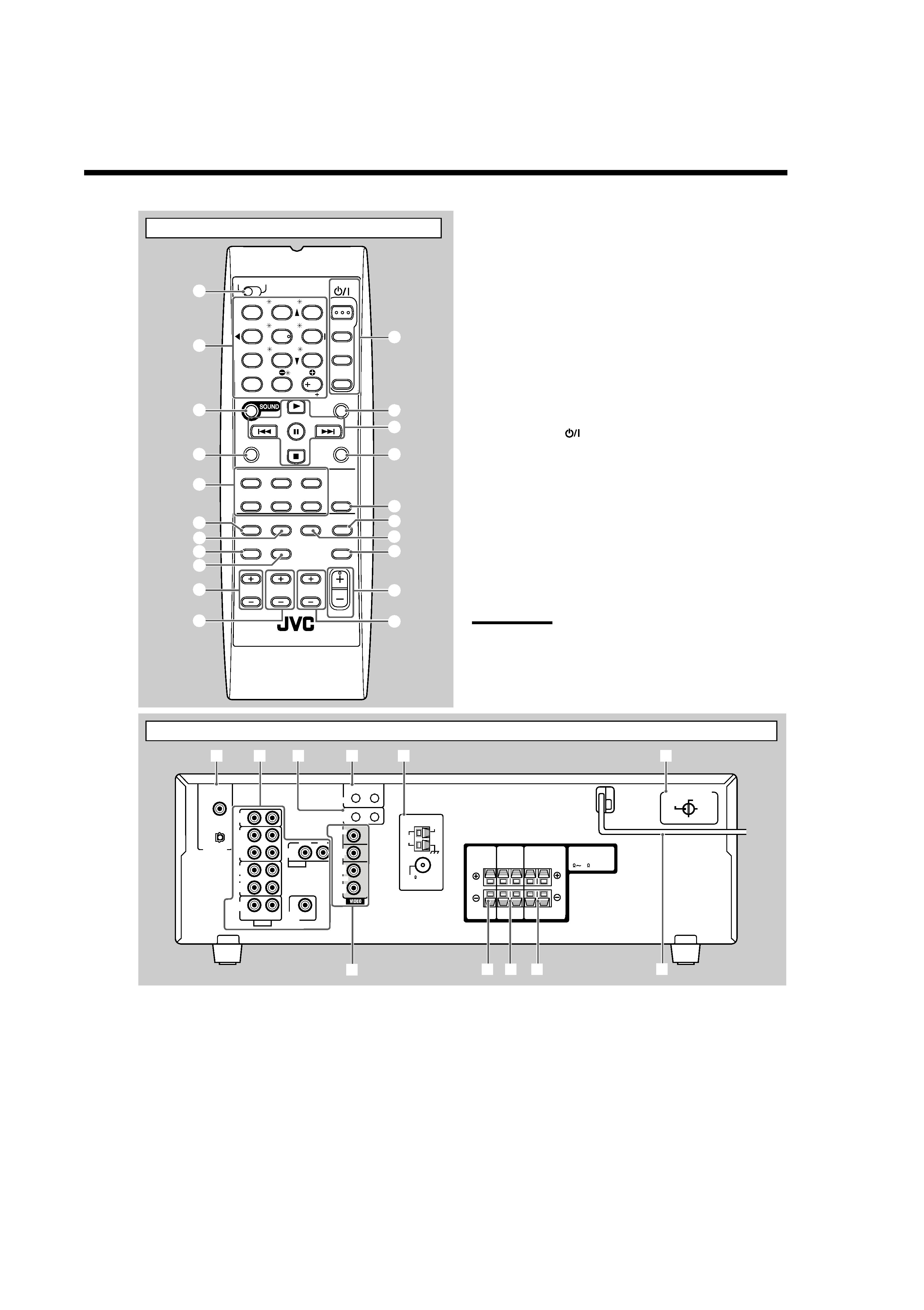
See pages in parentheses for details.
1 TV/CATV selector (33)
2 10 keys for selecting preset channels (15, 31)
10 keys for sound adjustment (22, 31)
10 keys for operating audio/video components (31 33)
3 SOUND button (22, 31)
4 REC PAUSE button (32, 34)
5 Source selection buttons (9, 10)
TAPE/CDR, CD, DVD, FM/AM, TV SOUND, VCR
6 FM MODE button (15, 31)
7 SURROUND button (25, 31)
8 DIMMER button (12, 31)
9 TV/VIDEO button (32, 33)
0 VCR CH +/ buttons (32, 34)
- TV/CATV CH +/ buttons (32, 33)
= STANDBY/ON
buttons (9, 31 34)
AUDIO, TV/CATV, VCR, DVD
~ SLEEP button (13, 31)
! Operating buttons for audio/video components
3, 8, 7, ¢/4, FF/REW (31 34)
@ CD-DISC button (31)
# ANALOG/DIGITAL button (11, 12, 31)
$ SURROUND/DSP OFF button (25, 27, 31)
% DSP button (26, 27, 31)
^ MUTING button (13, 31)
& VOLUME +/ button (10, 31)
* TV VOLUME +/ buttons (32, 33)
Note:
When you press the one of the audio source selection buttons--
TAPE/CDR, CD, and FM/AM--on the remote control, the receiver
automatically turns on.
AUDIO
TV/CATV
VCR
DVD
TEST
EFFECT
MENU
ENTER
LEVEL
RETURN
SURROUND
/DSP
CD-DISC
SLEEP
REC PAUSE
FM MODE SURROUND
DSP
DIMMER
TV/VIDEO
MUTING
OFF
VCR CH
TV/CATV CH
VOLUME
SURR R
SURR L
SUBWFR
CENTER
FRONT R
FRONT L
100
1
4
7/P
10
2
5
8
0
3
6
9
10
TV VOLUME
STANDBY/ON
TV
CATV
A/V CONTROL
RECEIVER
TAPE/CDR
CD
DVD
FM/AM
TV SOUND
VCR
ANALOG
/DIGITAL
REW
FF
2
5
=
$
%
#
@
^
4
8
7
0
-
*
&
6
9
~
3
1
!
Rear Panel
See pages in parentheses for details.
1 DIGITAL IN terminals (8)
· Coaxial:
DIGITAL 1 (DVD)
· Optical:
DIGITAL 2 (CD)
2 Audio input/output jacks (6, 7)
· Input:
CD IN, TAPE/CDR IN (PLAY), VCR IN (PLAY),
TV SOUND IN, DVD IN
· Output: TAPE/CDR OUT (REC), VCR OUT (REC),
SUBWOOFER OUT
3 COMPU LINK-4 (SYNCHRO) jacks (28)
4 AV COMPU LINK jacks (29)
5 ANTENNA terminals (4, 5)
6 VOLTAGE SELECTOR switch (8)
7 VIDEO input/output jacks (7)
· Input:
DVD IN, VCR IN (PLAY)
· Output:
MONITOR OUT, VCR OUT (REC)
8 CENTER SPEAKER terminals (5)
9 SURROUND SPEAKERS terminals (5)
p FRONT SPEAKERS terminals (5)
q AC power cord (8)
CAUTION :
SPEAKER IMPEDANCE
AM
LOOP
AM
EXT
CD
IN
OUT
(REC)
IN
(PLAY)
OUT
(REC)
VCR
TV SOUND
IN
AV
COMPU LINK
COMPU LINK-4
(SYNCHRO)
ANTENNA
CENTER
SPEAKER
SURROUND
SPEAKERS
RIGHT LEFT
FRONT
SPEAKERS
RIGHT LEFT
AUDIO
RIGHT
LEFT
IN
(PLAY)
TAPE
/CDR
DIGITAL 1
DIGITAL 2 ( CD )
DIGITAL IN
(DVD)
SUBWOOFER
OUT
AUDIO
COAXIAL
FM 75
816
MONITOR
OUT
DVD
IN
OUT
(REC)
VCR
IN
(PLAY)
DVD
IN
RIGHT
LEFT
3
14
5
q
8 9p
2
7
VOLTAGE SELECTOR
220V
230 - 240V
127V
110V
6
01-08_5040B[UJ].p65
04.4.15, 2:30 PM
3