SERVICE MANUAL
AUDIO/VIDEO CONTROL RECEIVER
No.20883
Nov. 2000
COPYRIGHT
2000 VICTOR COMPANY OF JAPAN, LTD.
RX-5000VBK
RX-5001VGD
UF
US
China
Singapore
Area Suffix
Contents
Safety precautions ---------------- 1-2
Disassembly method ------------- 1-3
Adjustment method --------------- 1-5
Description of major ICs --------- 1-6
Internal connections for
FL display tube ----- 1-15
4
1
7
4
1
RM-SR558U REMOTE CONTROL
TAPE/MD
FM/AM
VCR
DVD
SOUND
CONTROL
SLEEP
8
3
2
1
5
SURROUND
TEST
DELAY
6
5
4
EFFECT
CENTER +
5
9
8
7/P
REAR·L +
5
TV
VCR
AUDIO
CD
+10
10
REAR·R +
MENU
ENT
5
+
TV CH
TV/VIDEO
PHONO
CD-DISC
+
TV VOL.
DVD MULTI
ONE TOUCH
OPERATION
VCR CH
+
+
MUTING
VOLUME
£
POWER
RX-5000V
AUDIO/VIDEO CONTROL RECEIVER
STANDBY
PHONES
SPEAKERS
12
ADJUST
BASS BOOST
SETTING
MEMORY
DVD MULTI
CD
DVD
PHONO
VCR
TAPE/MD
SOURCE NAME
FM
SURROUND
MULTI CURSOR
INPUT ATT.
ONE TOUCH OPERATION
AM
MASTER VOLUME
+
OFF
_ ON
POWER
RX-5000VBK
RX-5001VGD
RX-5000VBK/RX-5001VGD
1-2
Safety Precautions
1. This design of this product contains special hardware and many circuits and components specially
for safety purposes.
For continued protection, no changes should be made to the original design
unless authorized in writing by the manufacturer.
Replacement parts must be identical to those
used in the original circuits.
Services should be performed by qualified personnel only.
2. Alterations of the design or circuitry of the product should not be made.
Any design alterations of
the product should not be made.
Any design alterations or additions will
void the manufacturer`s
warranty and will further relieve the manufacture of responsibility for personal injury or property
damage resulting therefrom.
3. Many electrical and mechanical parts in the products have special safety-related characteristics.
These characteristics are often not evident from visual inspection nor can the protection afforded
by them necessarily be obtained by using replacement components rated for higher voltage,
wattage, etc.
Replacement parts which have these special safety characteristics are identified in
the Parts List of Service Manual.
Electrical components having such features are identified by
shading on the schematics and by (
) on the Parts List in the Service Manual.
The use of a
substitute replacement which does not have the same safety characteristics as the recommended
replacement parts shown in the Parts List of Service Manual may create shock, fire, or other
hazards.
4. The leads in the products are routed and dressed with ties, clamps, tubings, barriers and the
like to be separated from live parts, high temperature parts, moving parts and/or sharp edges
for the prevention of electric shock and fire hazard.
When service is required, the original lead
routing and dress should be observed, and it should be confirmed that they have been returned
to normal, after re-assembling.
5. Leakage currnet check (Electrical shock hazard testing)
After re-assembling the product, always perform an isolation check on the exposed metal parts
of the product (antenna terminals, knobs, metal cabinet, screw heads, headphone jack, control
shafts, etc.) to be sure the product is safe to operate without danger of electrical shock.
Do not use a line isolation transformer during this check.
Plug the AC line cord directly into the AC outlet.
Using a "Leakage Current Tester", measure
the leakage
current from each exposed metal parts of the cabinet , particularly any exposed
metal part having a return path to the chassis, to a known good earth ground. Any leakage
current must not exceed 0.5mA AC (r.m.s.)
Alternate check method
Plug the AC line cord directly into the AC outlet.
Use an AC voltmeter having, 1,000 ohms
per volt or more sensitivity in the following manner. Connect a 1,500
10W resistor paralleled by
a 0.15 F AC-type capacitor between an exposed
metal part and a known good earth ground.
Measure the AC voltage across the resistor with the
AC voltmeter.
Move the resistor connection to eachexposed metal
part, particularly any exposed metal part having a
return path to the chassis, and meausre the AC
voltage across the resistor. Now, reverse the plug in
the AC outlet and repeat each measurement. voltage
measured Any must not exceed 0.75 V AC (r.m.s.).
This corresponds to 0.5 mA AC (r.m.s.).
Warning
1. This equipment has been designed and manufactured to meet international safety standards.
2. It is the legal responsibility of the repairer to ensure that these safety standards are maintained.
3. Repairs must be made in accordance with the relevant safety standards.
4. It is essential that safety critical components are replaced by approved parts.
5. If mains voltage selector is provided, check setting for local voltage.
Good earth ground
Place this
probe on
each exposed
metal part.
AC VOLTMETER
(Having 1000
ohms/volts,
or more sensitivity)
1500
10W
0.15 F AC TYPE
! CAUTION Burrs formed during molding may be left over on some parts of the chassis. Therefore,
pay attention to such burrs in the case of preforming repair of this system.
RX-5000VBK/RX-5001VGD
1-3
Disassembly method
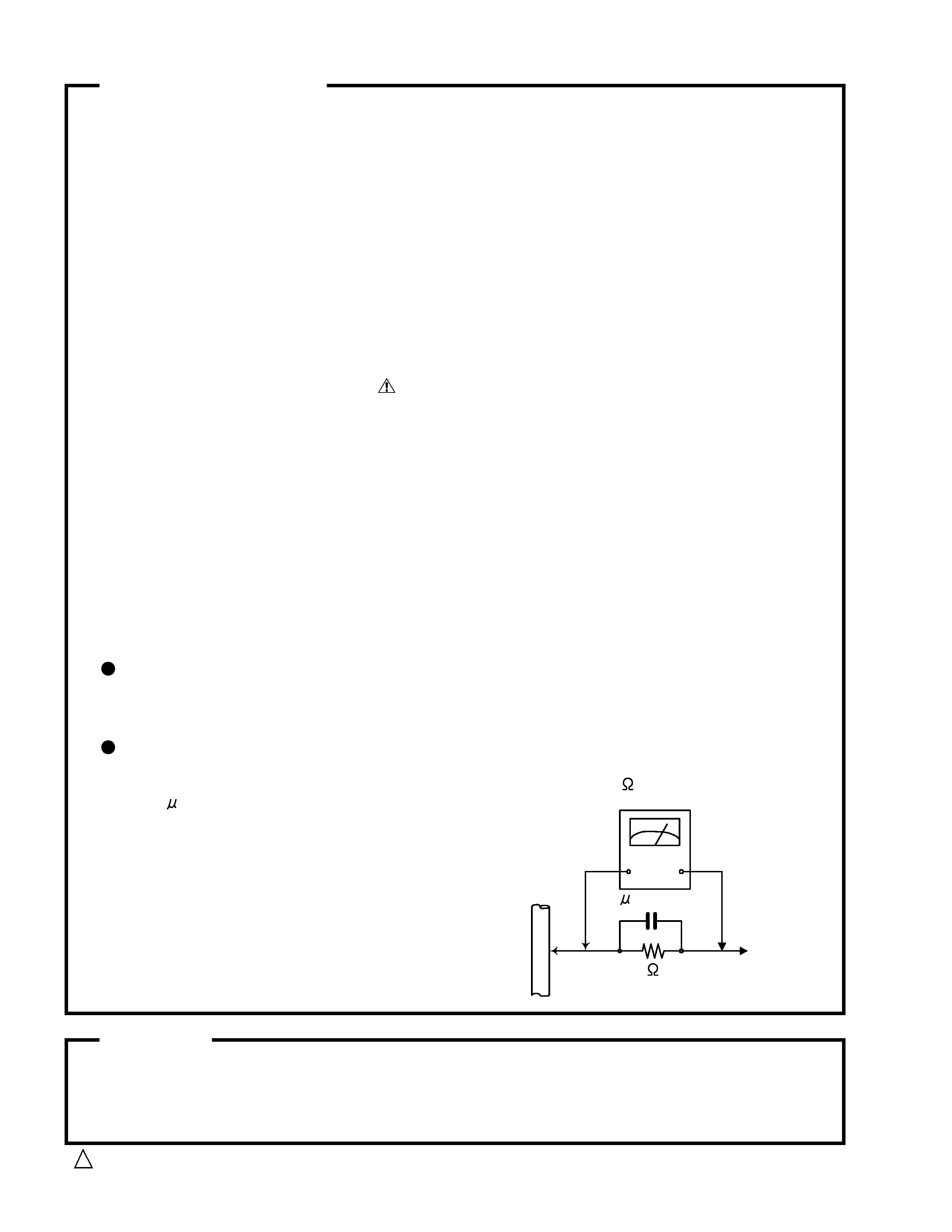
Removing the top cover (See Fig.1)
1. Remove 4 screws "A" on both sides of the top cover
and 3 screws "B" on the rear side.
2. Lift the back of the top cover spreading both sides
to remove.
Removing the front panel assembly (See Fig.2,3)
1. Remove the top cover.
2. Remove 4 screws "C" on the bottom side and 3 screws
"D" on the top side.
3. Disconnect the wire CN811 on the main board.
4. Disconnect the wire CN314 on the audio & source
selector board.
5. Remove the front panel assembly.
Removing the rear panel (See Fig.4)
1. Remove the top cover.
2. Remove 21 screws "E" on the rear panel.
3. Remove 3 screws "F" on the rear panel.
4. Remove the power cord stopper up side.
5. Remove the rear panel.
Removing the tuner board and
video board (See Fig.5)
1. Remove the rear panel.
2. Remove 1 screw "G" on the video board
3. Disconnect the connector CN311 on the
video board
4. Disconnect the connector CN111 on the
audio & source selector board.
A 2
A 2
B
B
B
Fig.1
C
C
C
C
Fig.2
BOTTOM COVER
Fig.4
Power cord
Stopper
E
CN311
G
VIDEO board
Fig.5
Audio &
source
selector
board
Tuner
board
CN111
D
D
D
Fig.3
CN811
CN314
Main
board
Audio &
source
selector
board
F
F
F
E
E
E
E
RX-5000VBK/RX-5001VGD
1-4
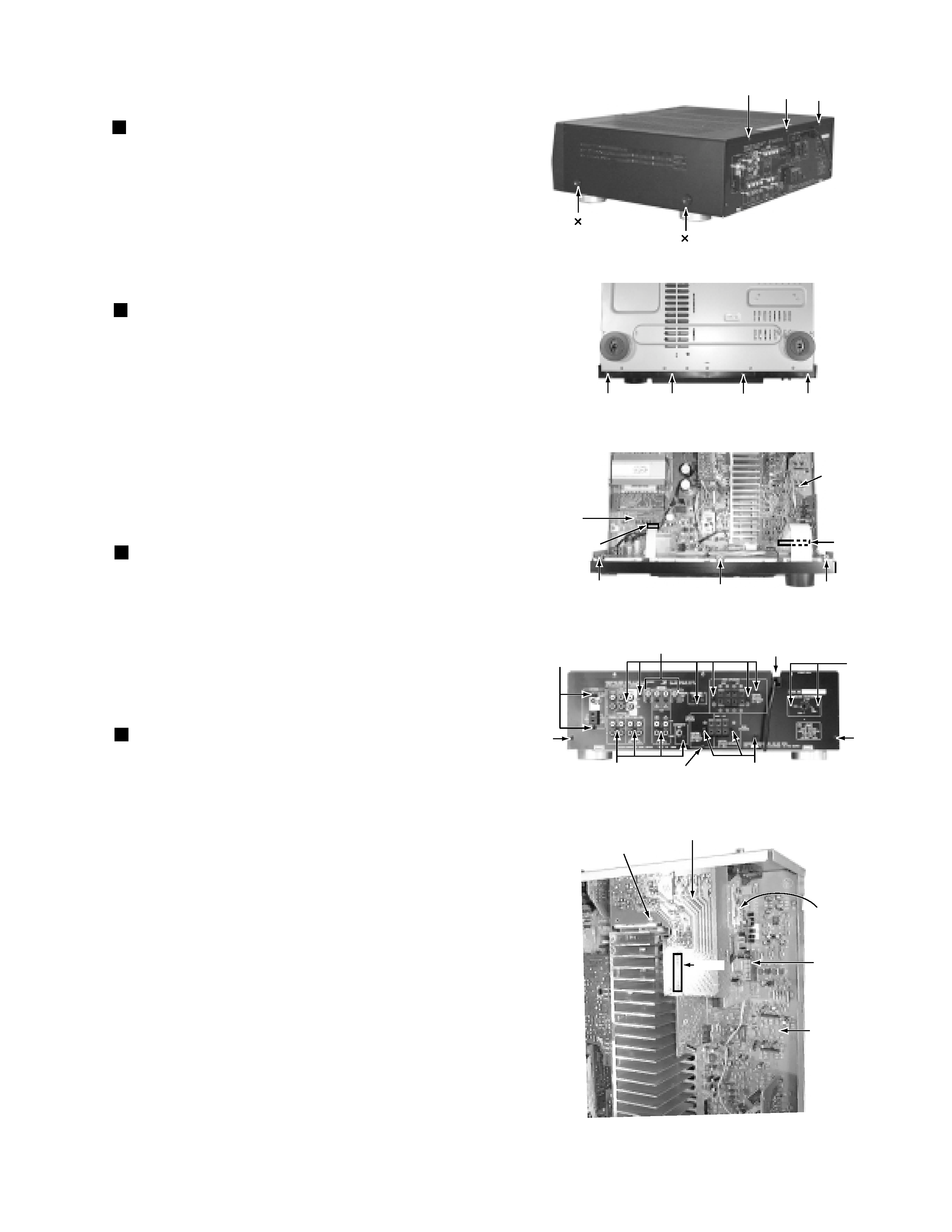
Removing the audio & source selector
board (See Fig.6)
1. Remove the rear panel.
2. Remove the video board and Tuner board.
3. Disconnect the connector CN512 and CN619 on the
audio & source selector board.
4. Disconnect to the card wire CN314 on the audio &
source selector board.
5. Disconnect the connector CN712 on the AMP board.
6. Each tie band is cut out.
7. Pullout the connection board.
8. Remove 4 screws "H" on the audio & source
selector board.
9. Remove the audio & source selector board.
Removing the main board (See Fig.6 to 8)
1. Remove the rear panel and front panel assembly.
2. Pull out the pre AMP board and connection board.
3. Remove 8 screws "I" on the main board.
4. Remove 8 screws "J" on the power transistor.
5. Disconnect the connector CN511 and wire
CN831 on the main board.
6. Each tie band is cut out.
7. Remove 2 screws "K" on push switch of the front side.
8. Remove nut on terminal of the headphone.
9. The solder of the wire connected with the
transformer is removed.
10. Remove the main board.
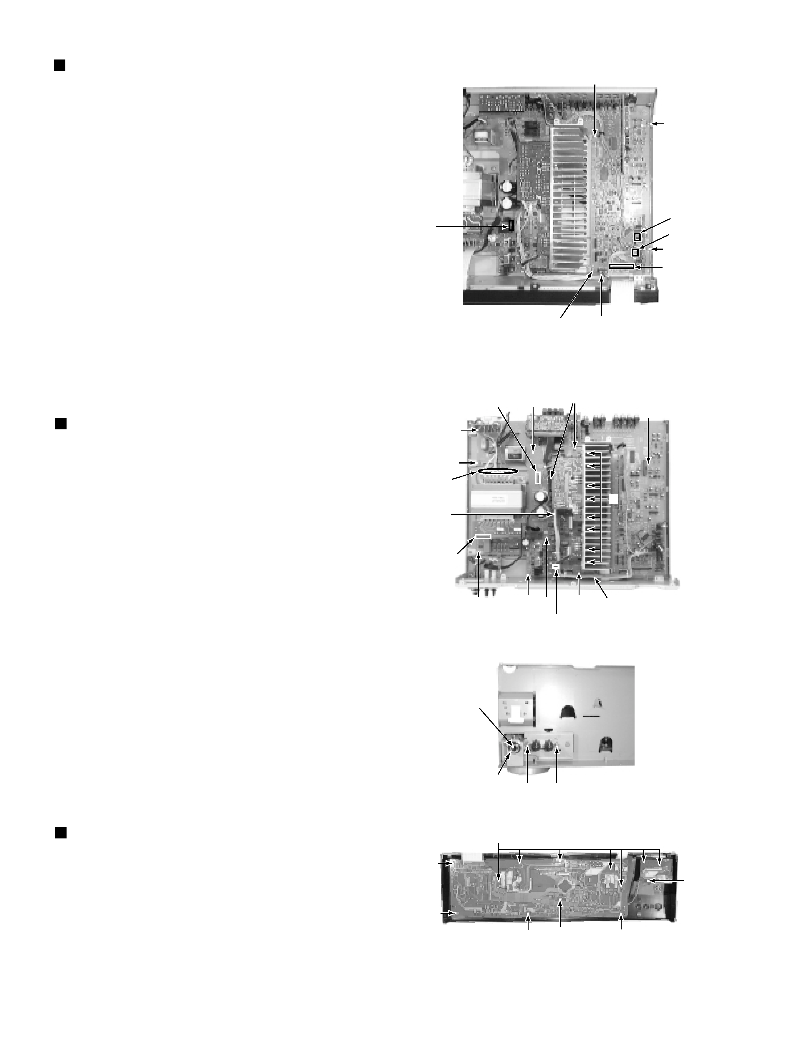
Removing the front board (See Fig.9)
1. Remove the top cover.
2. Remove the Front panel assembly.
3. Remove the master volume knob and nut.
4. Remove the 13 screws "L" on the Front board.
CN712
H
H
H
Connection board
(Standing substrate)
H
CN512
CN314
Fig.6
Audio & source
selector board
Audio & source
selector board
Fig.8
NUT
KK
Headphone jack
Fig.9
L
L
L
L
L
L
L
CN511
Pre AMP board
(Standing substrate)
CN831
J
Main
PCB
Fig.7
I
I
I
I
I
I
I
Solder
Solder
Audio & source
selector board
Connection
board
CN619
RX-5000VBK/RX-5001VGD
1-5
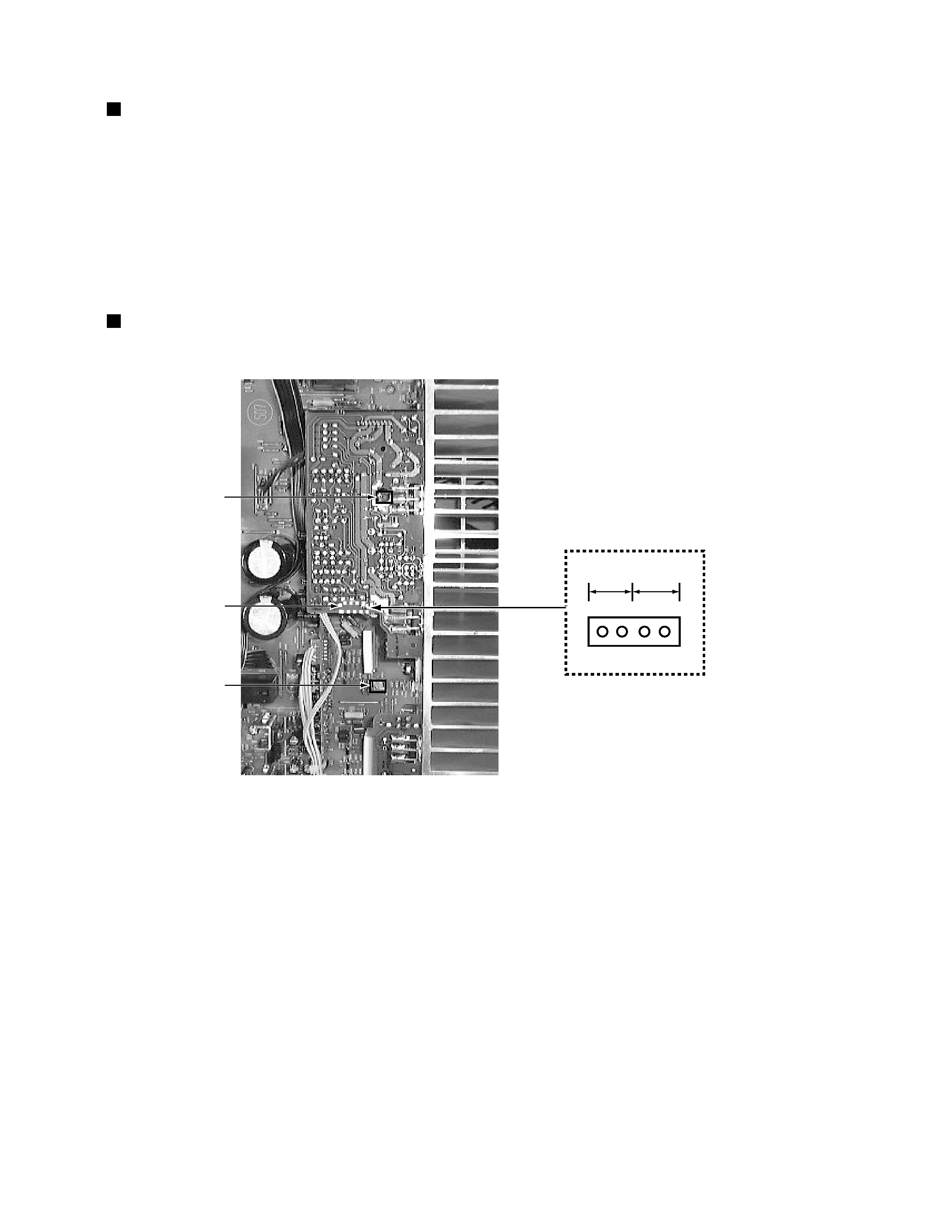
Adjustment method
IDLING CURRENT
1.Set the volume control to minimum during this adjustment.
2.Set the surround mode OFF.
2.Turn VR741 and VR742 fully counterclockwise to warm up before adjustment.
If the heat sink is already warm from previous use the correct adjustment can not be made.
3.For L-ch,connect a DC voltmeter between TP001's pin1 and pin2 (Lch)
And,connect it between pin3 and pin4(Rch).
4.30 minutes later after power on, adjust VR741 for L-ch, or VR742 for R-ch so that the DC voltmeter
value has 1mV~10mV.
1.Tuner range
FM
87.5MHz~108.0MHz
AM(MW)
530kHz~1710kHz
VR742
TP001
VR741
4 3 2 1
Lch
Rch
TP001
TUNER SECTION
POWER AMPLIFIER SECTION