SERVICE MANUAL
COPYRIGHT © 2003 VICTOR COMPANY OF JAPAN, LTD.
No.52110
2003/04
RK-CPDP1
TABLETOP STAND
52110
2003
04
RK-CPDP1
TABLE OF CONTENTS
1
ASSEMBLY INSTRUCTIONS . . . . . . . . . . . . . . . . . . . . . . . . . . . . . . . . . . . . . . . . . . . . . . . . . . . . . . . . . . . . 1-2
2
PARTS LIST . . . . . . . . . . . . . . . . . . . . . . . . . . . . . . . . . . . . . . . . . . . . . . . . . . . . . . . . . . . . . . . . . . . . . . . . . . 1-4
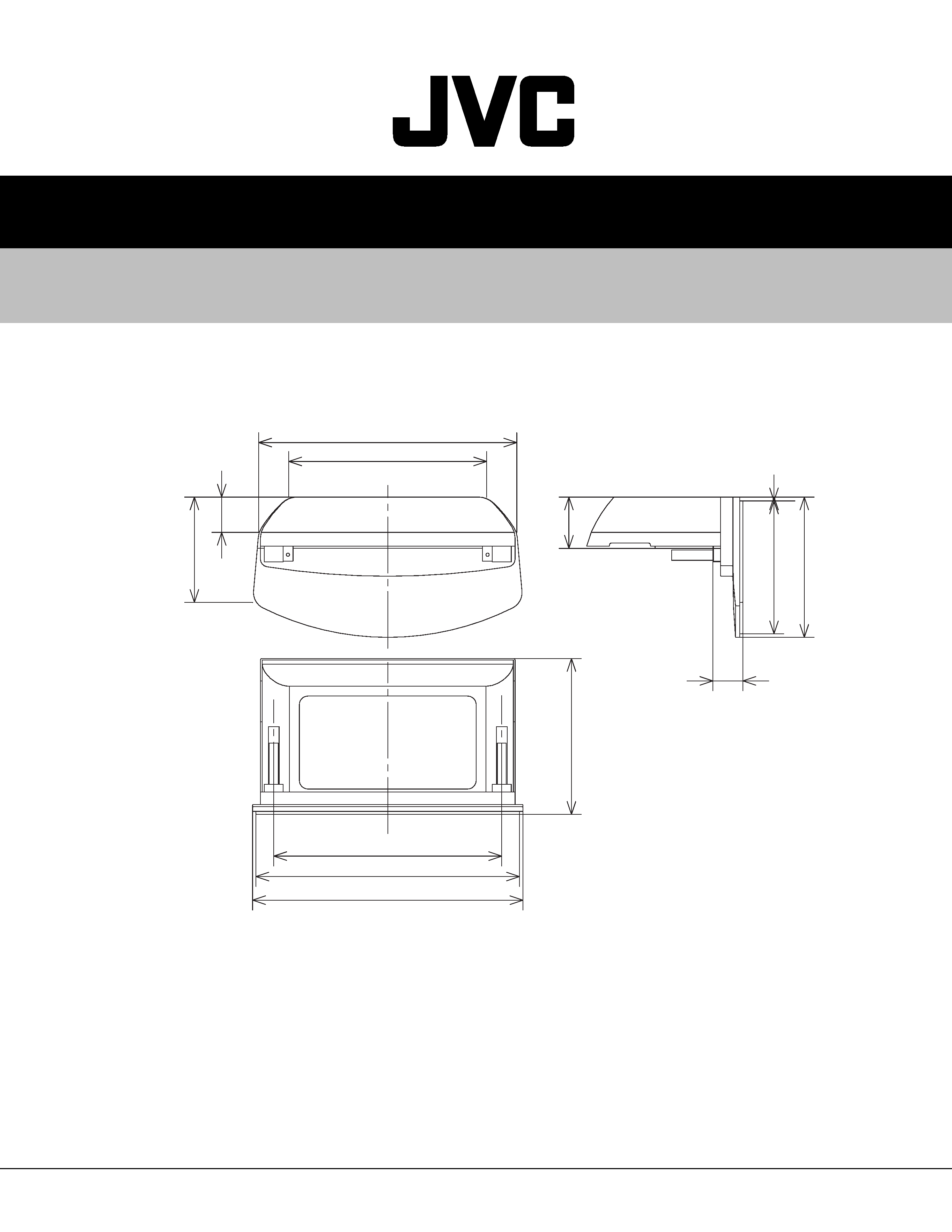
710
362.3
326
9
309
119.3
70
612.5
460
245
530
600
82
Mass : 8kg
RK-CPDP1
1-2 (No.52110)
ASSEMBLY INSTRUCTIONS
Assembly
Instructions
Tabletop
Stand
RK-CPDP1
Thank
you
for
purchasing
the
Tabletop
Stand.
Please
read
this
manual
thoroughly
in
order
to
ensure
correct
assembly
of
the
product.
The
safety
precautions
on
the
back
should
be
read
first.
Look
at
the
diagram
below
and
check
the
number
of
parts.
If
any
parts
are
missing,
please
contact
your
retailer.
You
will
need
a
Phillips
screwdriver
(+).
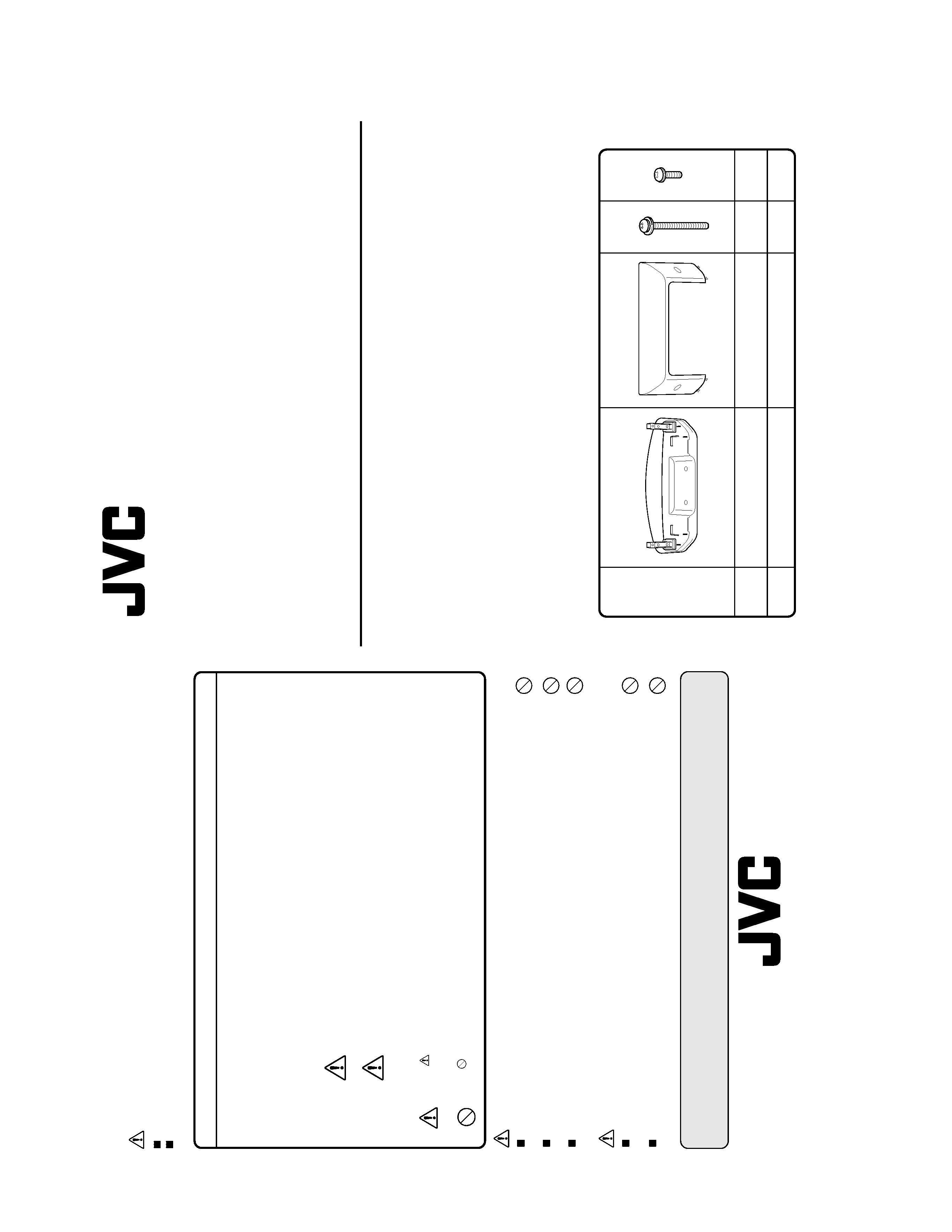
Composite
Parts
Diagram
Part
Name
Quantity
Washer
Washer
Stand
Cover
Screws
Screws
(long)
(short)
11
4
2
For
correct
and
safe
use
Please
read
these
precautions
carefully
before
use.
The
Symbols
The
symbols
used
in
this
manual
provide
information
and
precautions
regarding
the
product
to
encourage
safe
use
and
to
protect
people
and
property
from
damage.
The
symbols
and
their
meanings
are
as
follows.
Make
sure
you
are
aware
of
the
meaning
of
each
symbol
before
reading
the
instructions.
Mistaken
use
resulting
from
failure
to
read
content
marked
with
this
symbol
may
cause
accidents
leading
to
death
or
serious
injury.
Mistaken
use
resulting
from
failure
to
read
content
marked
with
this
symbol
may
cause
accidents
limited
to
minor
injury
or
property
damage.
Example
of
symbol
use
The
symbol
indicates
content
advising
caution
(including
possible
dangers
and
warnings).
Specific
caution
content
is
written
within
the
diagram.
The
symbol
indicates
content
which
explains
actions
that
are
prohibited.
Details
of
prohibited
content
are
written
either
within
the
diagram
or
nearby.
Precautions
During
Use
Precautions
when
installing
a
Plasma
Display
Caution
Carry
out
Plasma
Display
installation
with
at
least
2
persons.
Avoid
inserting
fingers
into
the
gap
between
the
Tabletop
Stand
and
the
Plasma
Display
during
installation,
as
fingers
may
get
trapped,
causing
injury.
Warning
Caution
Warning
Do
not
place
the
Tabletop
Stand
on
an
unsteady
or
slanting
surface
or
other
unstable
location,
as
falls
or
injury
may
result.
Do
not
move
the
Tabletop
Stand
with
the
device
mounted.
Vibration
or
shock
may
cause
damage
to
the
Tabletop
Stand's
connectors,
or
the
device
may
fall,
causing
injury.
Do
not
place
heavy
objects
other
than
the
stipulated
device
on
the
Tabletop
Stand,
as
balance
may
be
affected
and
the
device
may
fall
and
cause
injuries.
Caution
Do
not
place
the
Tabletop
Stand
in
direct
sunlight
or
next
to
a
heat
source,
as
this
may
cause
deformation
or
discoloration.
Do
not
drag
the
Tabletop
Stand
when
moving
it,
as
the
metal
legs
may
become
bent
or
leave
scratch
marks
on
floors.
Maintenance
Wipe
the
Tabletop
Stand
gently
with
a
soft,
dry
cloth.
Use
of
a
wet
cloth
may
result
in
surface
discoloration
or
rusting
of
the
frame.
©
2002
VICTOR
COMPANY
OF
JAPAN,
LIMITED
VICTOR
COMPANY
OF
JAPAN,
LIMITED
RK-CPDP1
(No.52110)1-3
Mounting
the
Plasma
Display
on
the
Tabletop
Stand
*
This
task
must
be
performed
by
at
least
two
persons.
q
Insert
the
Plasma
Display
Base
(A)
into
the
Plasma
Mounting
Brackets
(B).
w
Secure
the
Plasma
Display
at
(C)
with
the
4
long
Washer
Screws.
(A)
(B)
(C)
Connecting
the
Plasma
Display
wiring
(D)
(Indented
section)
q
The
system
cable
should
be
fed
out
through
(D)
(indented
section).
w
Connect
the
Speaker
Cord
(for
the
Front
Speaker)
to
the
Front
Speaker
and
the
Plasma
Display.
Fitting
the
Cover
on
the
Tabletop
Stand
w
Secure
the
cover
in
position
at
(H)
with
the
2
short
Washer
Screws.
(F)
(G)
(H)
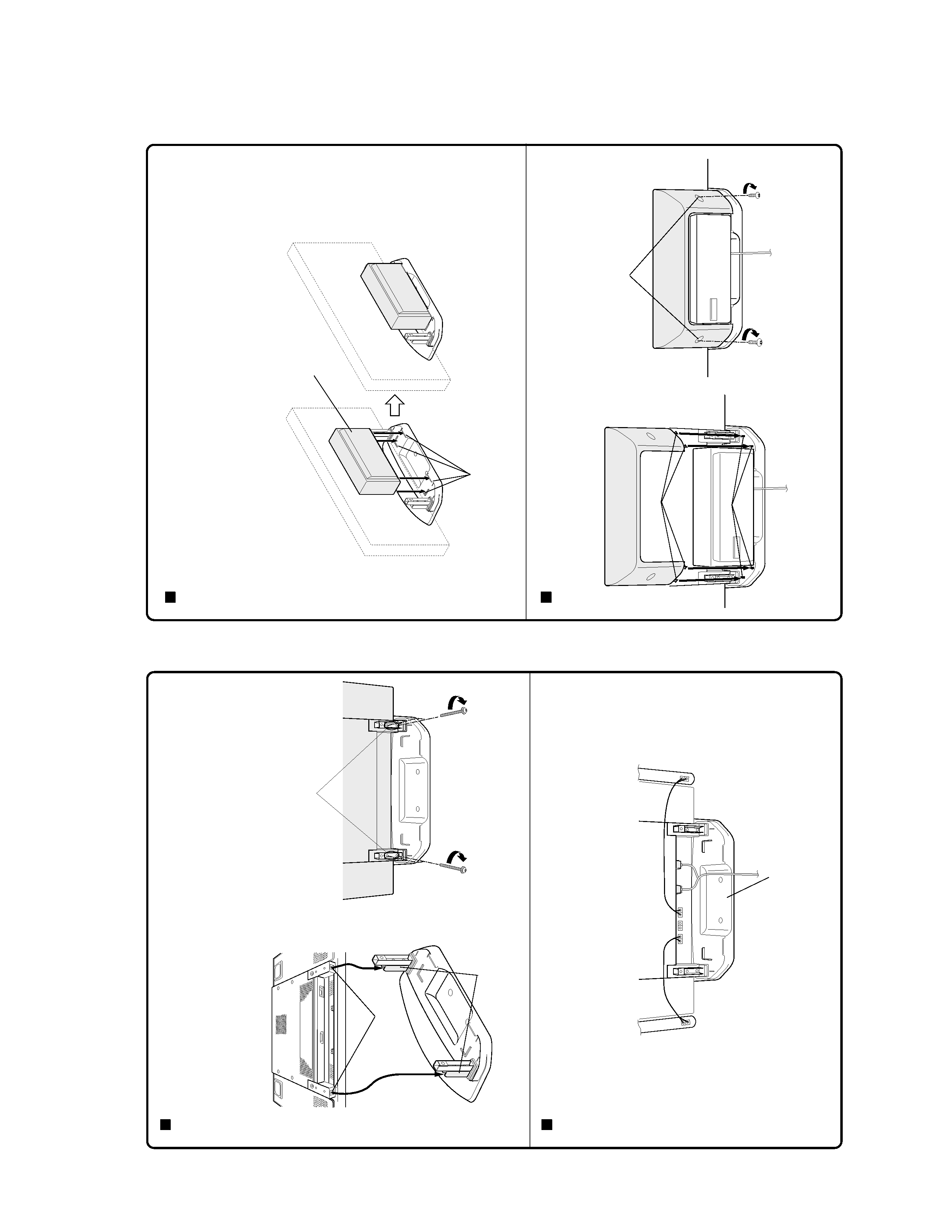
Attaching
the
Sub-Woofer
to
the
Tabletop
Stand.
q
Connect
the
Speaker
Cord
(For
the
Woofer)
to
the
Sub-Woofer
and
Plasma
Display.
w
After
connecting
the
Speaker
Cord,
turn
the
Sub-Woofer
so
that
the
net
cover
faces
outwards,
and
fit
the
Sub-Woofer
into
(E)
(Sub-Woofer
Positioning
Tabs).
*
While
positioning
the
Sub-Woofer,
care
should
be
taken
that
the
power
cord/system
cord
should
not
get
unplugged
or
loosened-up
from
the
Plasma
Display.
(E)
(Sub-Woofer
Positioning
Tabs)
The
above
diagram
shows
the
Sub-Woofer
in
position
in
the
Tabletop
Stand.
q
Insert
the
Tabs
(F)
on
the
bottom
of
the
Cover
into
slots
(G)
on
the
Tabletop
Stand.
(NET
COVER)
RK-CPDP1
1-4 (No.52110)
PARTS LIST
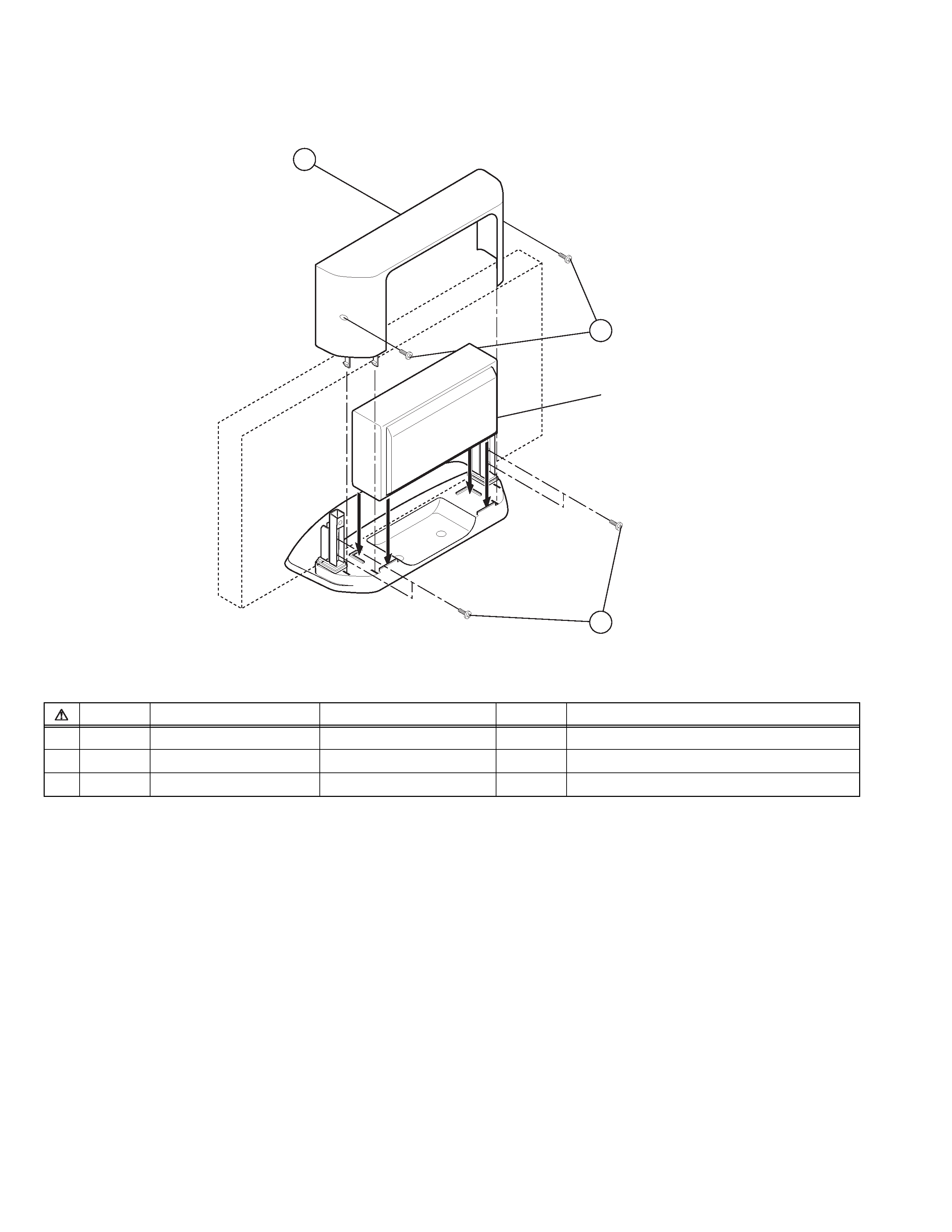
EXPLODED VIEW
EXPLODED VIEW PARTS LIST
Ref.No.
Part No.
Part Name
Qty
Description
1
LC11579-001A
COVER
1
2
C500S1
SCREW
4
For STAND (LONG) M5 x 30
3
C500S2
SCREW
2
For COVER (SHORT) M4 x 12
2
3
Sub-Woofer
1
RK-CPDP1
(No.52110)1-5
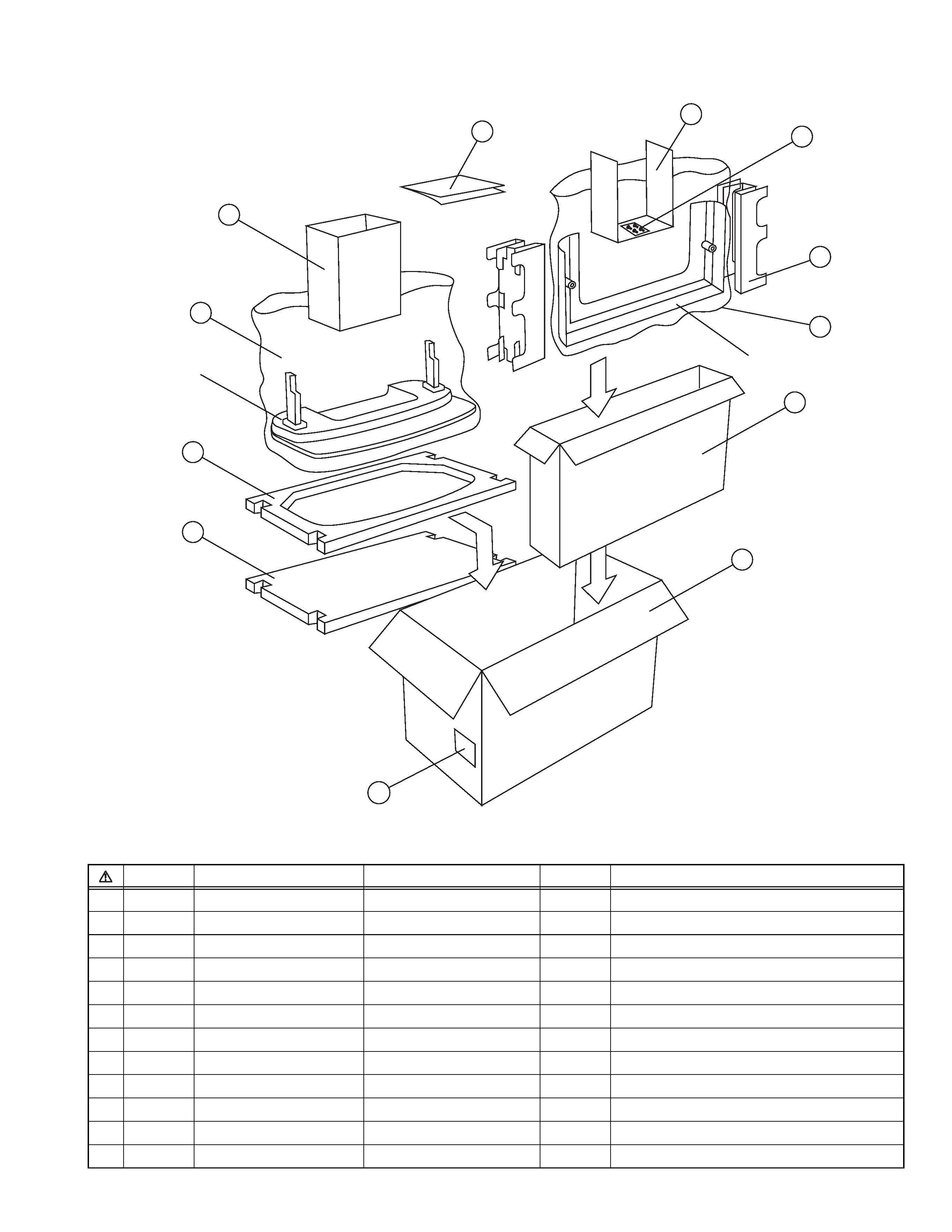
PACKING
PACKING PARTS LIST
Ref.No.
Part No.
Part Name
Qty
Description
1
C500P1
PACKING CASE
1
2
C500P3
CUSHION
1
3
C500P4
CUSHION
1
4
C500P6
CUSHION
1
5
C500P2
PACKING CASE
1
6
C500P7
CUSHION
2
7
C500P5
CUSHION
1
8
C500F1
POLY BAG
1
For STAND
9
C500F2
POLY BAG
1
For COVER
10
C500F3
POLY BAG
1
For SCREW
11
CPDP1INST
INSTSHEET
1
12
CP30902-074
POS LABEL
1
12
4
11
7
10
6
9
5
1
2
3
8
Stand
Cover