SERVICE MANUAL
CD PORTABLE SYSTEM
No.MB062
2003/11
COPYRIGHT
2003 VICTOR COMPANY OF JAPAN, LTD.
RC-ST1SL
RC-ST1RD
RC-ST1BK
Contents
Area Suffix
B -------------------------- U.K.
E -------Contnental Europe
EN ------- Northern Europe
EV --------- Eastern Europe
Specification--------------------------------------------------------------------------------------------1-2
SafetyPrecautions-----------------------------------------------------------------------------------1-3
Importantoflaserproducts------------------------------------------------------------------------1-5
preventingstaticelectricity-------------------------------------------------------------------------1-6
BlockDiagram----------------------------------------------------------------------------------------1-8
SchematicDiagrams------------------------------------------------------------------------------1-10
Assembly---------------------------------------------------------------------------------------------1-14
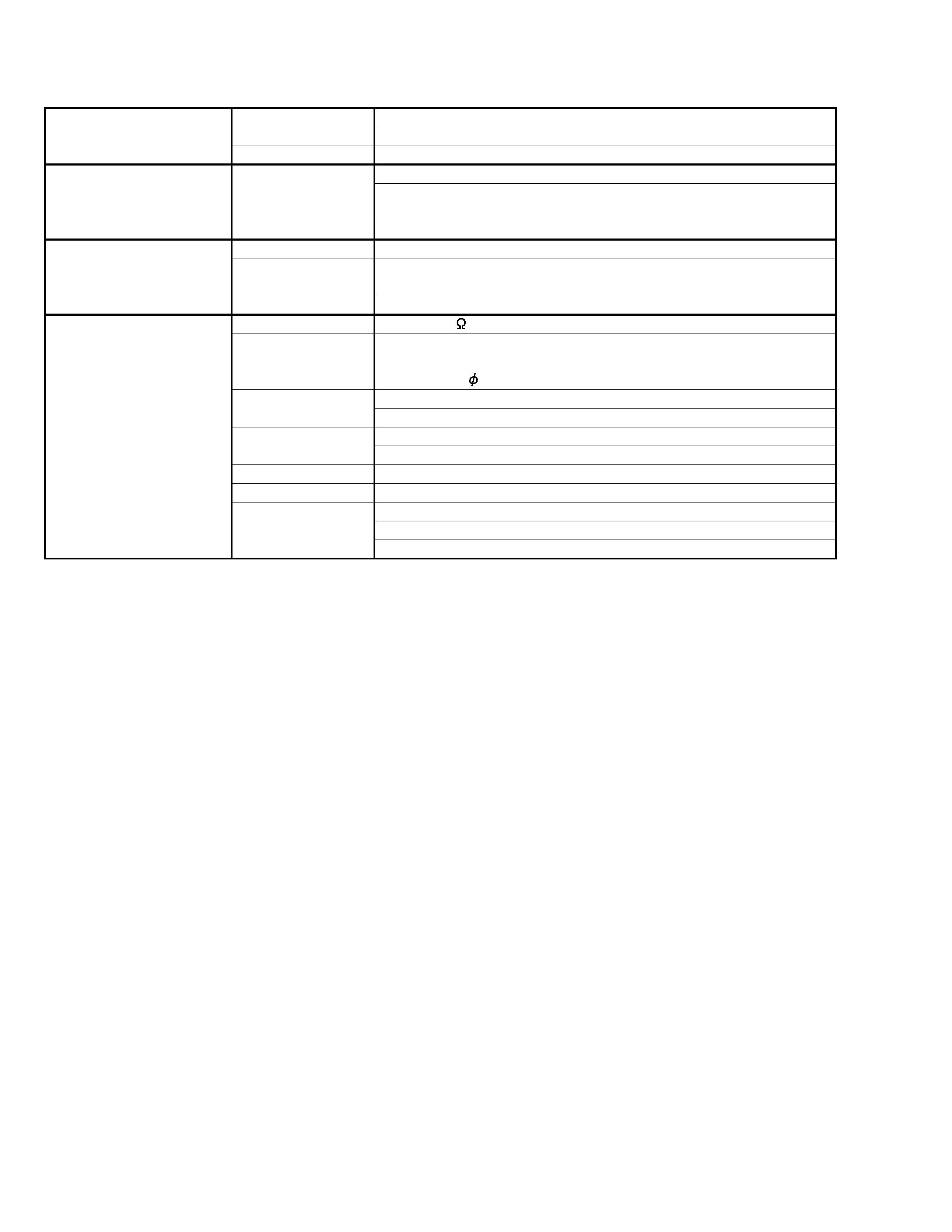
1-2
Compact disc player section Type
Compact disc player
Signal detection
Non-contact optical pick-up (semiconductor laser)
Number of channels
2 channels
Radio section
Frequency ranges
FM 88 MHz - 108 MHz
AM 530 kHz - 1,600 kHz
Antennas
Telescopic antenna for FM
Ferrite core antenna for AM
Cassette deck section
Track
4-track 2-channel stereo
Motor
Electronic governor DC motor for capstan
Heads
Hard permalloy head for recording/playback, magnetic head for erasure
Fast wind time
Approx. 120 sec. (C-60 cassette)
General
Speakers
10 cm × 2 (8 )
Power output
2 W per channel, min. RMS, driven into 8
at 1 kHz, with no more than
10% total harmonic distortion (IEC 268-3)
Output terminal
PHONES × 1 ( 3.5 mm, stereo)
Power supply
AC 230 V, 50 Hz
DC 12 V ("R20/D (13F)" cells × 8)
Power consumption
19 W (power-on mode)
2.5 W (standby mode)
Dimensions
440 mm (W) × 168 mm (H) × 241 mm (D)
Mass
Approx. 3 kg (without batteries)
Accessories provided AC power cord × 1
Remote control unit × 1
Batteries for remote control unit, R03 (UM-4)/AAA (24F) × 2
Specification
1-3
1. This design of this product contains special hardware and many circuits and components specially for safety
purposes. For continued protection, no changes should be made to the original design unless authorized in
writing by the manufacturer. Replacement parts must be identical to those used in the original circuits. Services
should be performed by qualified personnel only.
2. Alterations of the design or circuitry of the product should not be made. Any design alterations of the product
should not be made. Any design alterations or additions will void the manufacturer`s warranty and will further
relieve the manufacture of responsibility for personal injury or property damage resulting therefrom.
3. Many electrical and mechanical parts in the products have special safety-related characteristics. These
characteristics are often not evident from visual inspection nor can the protection afforded by them necessarily
be obtained by using replacement components rated for higher voltage, wattage, etc. Replacement parts which
have these special safety characteristics are identified in the Parts List of Service Manual. Electrical
components having such features are identified by shading on the schematics and by (
) on the Parts List in
the Service Manual. The use of a substitute replacement which does not have the same safety characteristics
as the recommended replacement parts shown in the Parts List of Service Manual may create shock, fire, or
other hazards.
4. The leads in the products are routed and dressed with ties, clamps, tubings, barriers and the like to be
separated from live parts, high temperature parts, moving parts and/or sharp edges for the prevention of
electric shock and fire hazard. When service is required, the original lead routing and dress should be
observed, and it should be confirmed that they have been returned to normal, after re-assembling.
5. Leakage currnet check (Electrical shock hazard testing)
After re-assembling the product, always perform an isolation check on the exposed metal parts of the product
(antenna terminals, knobs, metal cabinet, screw heads, headphone jack, control shafts, etc.) to be sure the
product is safe to operate without danger of electrical shock.
Do not use a line isolation transformer during this check.
Plug the AC line cord directly into the AC outlet. Using a "Leakage Current Tester", measure the leakage
current from each exposed metal parts of the cabinet, particularly any exposed metal part having a return
path to the chassis, to a known good earth ground. Any leakage current must not exceed 0.5mA AC (r.m.s.).
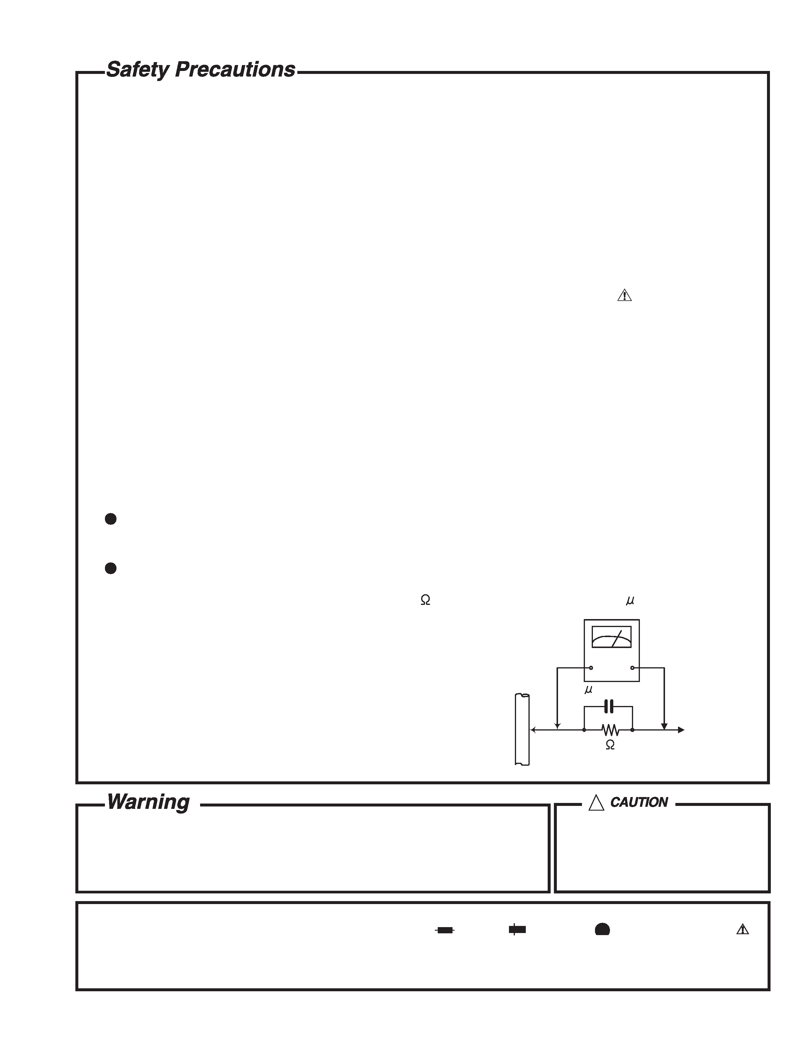
Alternate check method
Plug the AC line cord directly into the AC outlet. Use an AC voltmeter having, 1,000 ohms per volt or more
sensitivity in the following manner. Connect a 1,500
10W resistor paralleled by a 0.15 F AC-type capacitor
between an exposed metal part and a known good earth ground.
Measure the AC voltage across the resistor with the AC
voltmeter.
Move the resistor connection to each exposed metal part,
particularly any exposed metal part having a return path to
the chassis, and meausre the AC voltage across the resistor.
Now, reverse the plug in the AC outlet and repeat each
measurement. Voltage measured any must not exceed 0.75 V
AC (r.m.s.). This corresponds to 0.5 mA AC (r.m.s.).
1. This equipment has been designed and manufactured to meet international safety standards.
2. It is the legal responsibility of the repairer to ensure that these safety standards are maintained.
3. Repairs must be made in accordance with the relevant safety standards.
4. It is essential that safety critical components are replaced by approved parts.
5. If mains voltage selector is provided, check setting for local voltage.
Good earth ground
Place this
probe on
each exposed
metal part.
AC VOLTMETER
(Having 1000
ohms/volts,
or more sensitivity)
1500
10W
0.15 F AC TYPE
!
Burrs formed during molding may
be left over on some parts of the
chassis. Therefore, pay attention to
such burrs in the case of
preforming repair of this system.
In regard with component parts appearing on the silk-screen printed side (parts side) of the PWB diagrams, the
parts that are printed over with black such as the resistor (
), diode (
) and ICP (
) or identified by the " "
mark nearby are critical for safety.
(This regulation does not correspond to J and C version.)
1-4
1. Service should be performed by qualified personnel only.
2. This equipment has been designed and manufactured to meet international safety standards.
3. It is the legal responsibility of the repairer to ensure that these safety standards are maintained.
4. Repairs must be made in accordance with the relevant safety standards.
5. It is essential that safety critical components are replaced by approved parts.
6. If mains voltage selector is provided, check setting for local voltage.
1. This design of this product contains special hardware and many circuits and components specially
for safety purposes.
For continued protection, no changes should be made to the original
design unless authorized in writing by the manufacturer.
Replacement parts must be identical to
those used in the original circuits.
2. Any unauthorised design alterations or additions will void the manufacturer's guarantee ; furthermore the
manufacturer cannot accept responsibility for personal injury or property damage resulting therefrom.
3. Essential safety critical components are identified by (
) on the Parts List and by shading on the
schematics, and must never be replaced by parts other than those listed in the manual. Please note
however that many electrical and mechanical parts in the product have special safety related
characteristics. These characteristics are often not evident from visual inspection. Parts other than
specified by the manufacturer may not have the same safety characteristics as the recommended
replacement parts shown in the Parts List of the Service Manual and may create shock, fire, or
other hazards.
4. The leads in the products are routed and dressed with ties, clamps, tubings, barriers and the
like to be separated from live parts, high temperature parts, moving parts and/or sharp edges
for the prevention of electric shock and fire hazard.
When service is required, the original lead
routing and dress should be observed, and it should be confirmed that they have been returned
to normal, after re-assembling.
!
Burrs formed during molding may be left over on some parts of the chassis. Therefore,
pay attention to such burrs in the case of preforming repair of this system.
(U.K only)
1-5
Important for laser products
1.CLASS 1 LASER PRODUCT
2.DANGER : Invisible laser radiation when open and inter
lock failed or defeated. Avoid direct exposure to beam.
3.CAUTION : There are no serviceable parts inside the
Laser Unit. Do not disassemble the Laser Unit. Replace
the complete Laser Unit if it malfunctions.
4.CAUTION : The compact disc player uses invisible laser
radiation and is equipped with safety switches which
prevent emission of radiation when the drawer is open and
the safety interlocks have failed or are defeated. It is
dangerous to defeat the safety switches.
5.CAUTION : If safety switches malfunction, the laser is able
to function.
6.CAUTION : Use of controls, adjustments or performance of
procedures other than those specified herein may result in
hazardous radiation exposure.
VARNING : Osynlig laserstrålning är denna del är öppnad
och spårren är urkopplad. Betrakta ej strålen.
VARO
: Avattaessa ja suojalukitus ohitettaessa olet
alttiina näkymättömälle lasersäteilylle.Älä katso
säteeseen.
ADVARSEL : Usynlig laserstråling ved åbning , når
sikkerhedsafbrydere er ude af funktion. Undgå
udsættelse for stråling.
ADVARSEL : Usynlig laserstråling ved åpning,når
sikkerhetsbryteren er avslott. unngå utsettelse
for stråling.
Position and position of labels
WARNING LABEL
! CAUTION Please use enough caution not to
see the beam directly or touch it
in case of an adjustment or operation
check.
DANGER : Invisibie laser radiation
when open and interlock or
defeated.
AVOID DIRECT EXPOSURE TO
BEAM
(e)
VARNING : Osynlig laserstrålning
är denna del är öppnad och spårren
är
urkopplad. Betrakta ej strålen.
(s)
VARO : Avattaessa ja suojalukitus
ohitettaessa olet alttiina
näkymättömälle lasersäteilylle.Älä
katso säteeseen.
(d)
ADVARSEL :Usynlig laserstråling
ved åbning , når
sikkerhedsafbrydere er ude af
funktion. Undgå udsættelse for
stråling.
(f)
CLASS 1
LASER PRODUCT
CLASS 1
LASER PRODUCT
CLASS1 LABEL
PLACED OUTSIDE
THE UNIT
WAQRNING LABEL
PLACED INSIDE
THE UNIT