SERVICE MANUAL
COMPACT COMPONENT SYSTEM
No.21068
Feb. 2002
COPYRIGHT
2002 VICTOR COMPANY OF JAPAN, LTD.
MX-G500
MX-G500
Contents
Safety Precautions
Importance administering
point on the safety
Preventing static electricity
Disassembly method
Wiring connection
Adjustment method
Flow of functional operation
until TOC read
Maintenance of laser pickup
Replacement of laser pickup
Trouble shooting
Description of major ICs
1-2
1-3
1-4
1-5
1-18
1-19
1-23
1-24
1-24
1-25
1-28~41
Area suffix
J -------------------
U.S.A.
C ---------------- Canada
SP-MXG500
SP-MXG500
CA-MXG500
DISC CHANGE
C O MPU
P L A Y
C O N T R O L
STANDBY/ON
STAND BY
CD-R/RW PLAYBACK
CLOCK
/TIMER
DISPLAY
PHONES
REPEAT
REC START
/STOP
CD REC
START
DUBBING
PROGRAMRAND OM
TAPE B
TAPE A
AUX
TAPE
CD
FM
/ AM
SUBW OOFER
LEVEL
SOUND
MO DE
MX -G500
EXTEN DED SUPER BA SS
CD
3
FULL - L OGIC CONT ROL
CD SYN CHRO RECORDIN G
CD
1
CD
2
CD
3
DISC
SKIP
VOLUM E
VOLUM E
+
RM SMXG500 A R EM OTE CONT ROL
STAN DBY/ ON
12
3
4
5
6
78
9
10
+1 0
SLEEP
SOUN D
M ODE
TAPE A/B
FADE
MUTIN G
FM /A M
AUX
CD
TAPE
SUBW OOFER
LEVEL
FM M ODE
MX-G500
1-2
1. This design of this product contains special hardware and many circuits and components specially for safety
purposes. For continued protection, no changes should be made to the original design unless authorized in
writing by the manufacturer. Replacement parts must be identical to those used in the original circuits. Services
should be performed by qualified personnel only.
2. Alterations of the design or circuitry of the product should not be made. Any design alterations of the product
should not be made. Any design alterations or additions will void the manufacturer`s warranty and will further
relieve the manufacture of responsibility for personal injury or property damage resulting therefrom.
3. Many electrical and mechanical parts in the products have special safety-related characteristics. These
characteristics are often not evident from visual inspection nor can the protection afforded by them necessarily
be obtained by using replacement components rated for higher voltage, wattage, etc. Replacement parts which
have these special safety characteristics are identified in the Parts List of Service Manual. Electrical
components having such features are identified by shading on the schematics and by (
) on the Parts List in
the Service Manual. The use of a substitute replacement which does not have the same safety characteristics
as the recommended replacement parts shown in the Parts List of Service Manual may create shock, fire, or
other hazards.
4. The leads in the products are routed and dressed with ties, clamps, tubings, barriers and the like to be
separated from live parts, high temperature parts, moving parts and/or sharp edges for the prevention of
electric shock and fire hazard. When service is required, the original lead routing and dress should be
observed, and it should be confirmed that they have been returned to normal, after re-assembling.
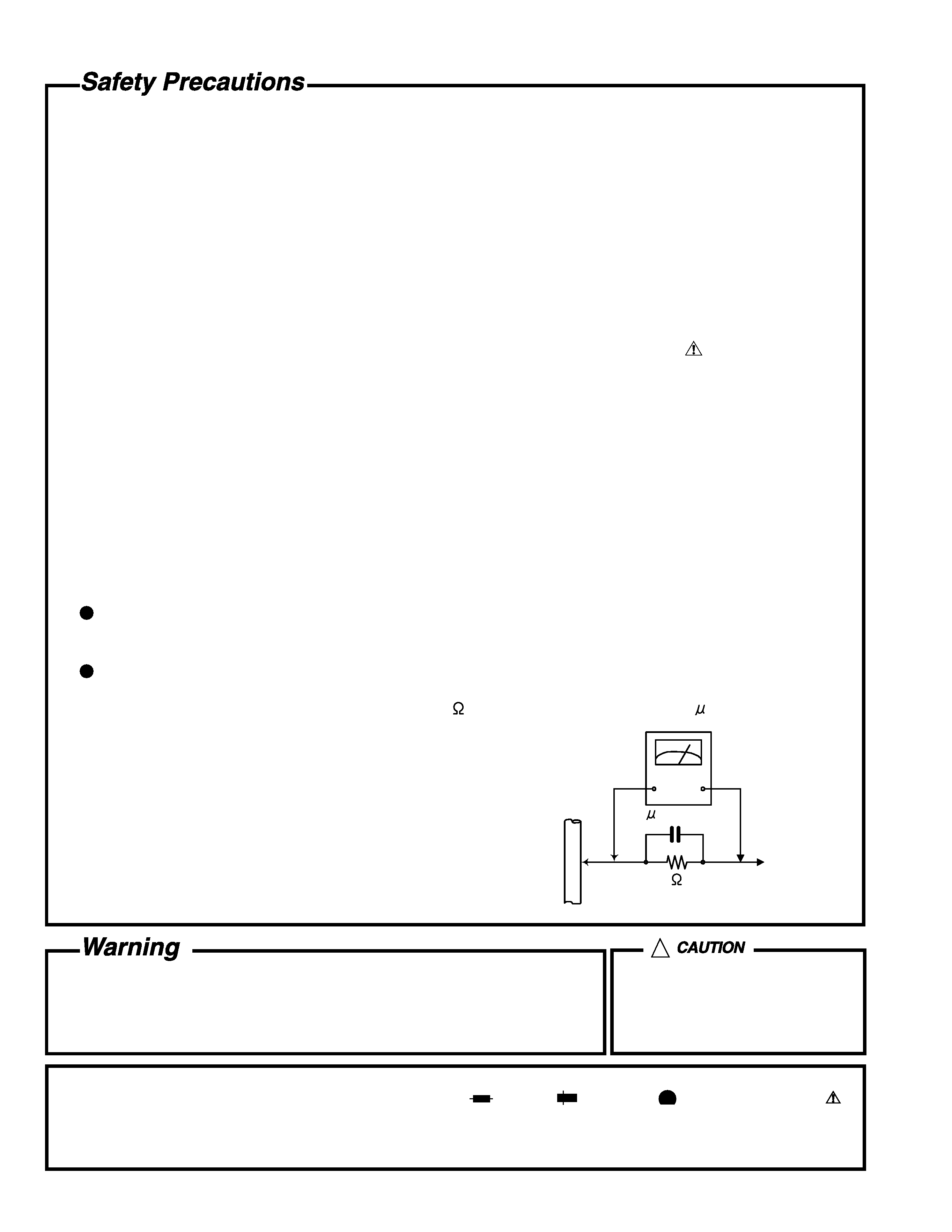
5. Leakage currnet check (Electrical shock hazard testing)
After re-assembling the product, always perform an isolation check on the exposed metal parts of the product
(antenna terminals, knobs, metal cabinet, screw heads, headphone jack, control shafts, etc.) to be sure the
product is safe to operate without danger of electrical shock.
Do not use a line isolation transformer during this check.
Plug the AC line cord directly into the AC outlet. Using a "Leakage Current Tester", measure the leakage
current from each exposed metal parts of the cabinet, particularly any exposed metal part having a return
path to the chassis, to a known good earth ground. Any leakage current must not exceed 0.5mA AC (r.m.s.).
Alternate check method
Plug the AC line cord directly into the AC outlet. Use an AC voltmeter having, 1,000 ohms per volt or more
sensitivity in the following manner. Connect a 1,500
10W resistor paralleled by a 0.15 F AC-type capacitor
between an exposed metal part and a known good earth ground.
Measure the AC voltage across the resistor with the AC
voltmeter.
Move the resistor connection to each exposed metal part,
particularly any exposed metal part having a return path to
the chassis, and meausre the AC voltage across the resistor.
Now, reverse the plug in the AC outlet and repeat each
measurement. Voltage measured any must not exceed 0.75 V
AC (r.m.s.). This corresponds to 0.5 mA AC (r.m.s.).
1. This equipment has been designed and manufactured to meet international safety standards.
2. It is the legal responsibility of the repairer to ensure that these safety standards are maintained.
3. Repairs must be made in accordance with the relevant safety standards.
4. It is essential that safety critical components are replaced by approved parts.
5. If mains voltage selector is provided, check setting for local voltage.
Good earth ground
Place this
probe on
each exposed
metal part.
AC VOLTMETER
(Having 1000
ohms/volts,
or more sensitivity)
1500
10W
0.15 F AC TYPE
!
Burrs formed during molding may
be left over on some parts of the
chassis. Therefore, pay attention to
such burrs in the case of
preforming repair of this system.
In regard with component parts appearing on the silk-screen printed side (parts side) of the PWB diagrams, the
parts that are printed over with black such as the resistor (
), diode (
) and ICP (
) or identified by the " "
mark nearby are critical for safety.
(This regulation does not correspond to J and C version.)
MX-G500
1-3
^
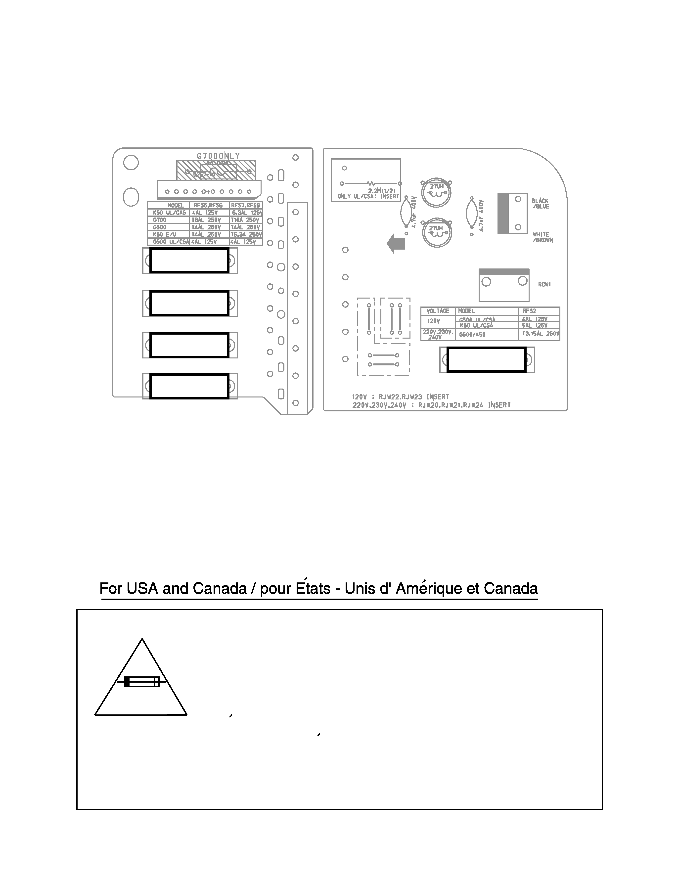
Importance administering point on the safety
Fuse board (Forward side)
Power supply board (Forward side)
4A 125V
4A 125V
4A 125V
4A 125V
4A 125V
RFS5
RFS6
RFS7
RFS8
RFS2
Caution: For continued protection against risk of fire,
replace only with same type 4A/125V for RFS2, RFS5,
RFS6, RFS7 and RFS8.
This symbol specifies type of fast operating fuse.
Precaution: Pour eviter risques de feux, remplacez le
fusible de surete de et RFS2, RFS5, RFS6, RFS7 et
RFS8 comme le meme type que 4A/125V.
Ce sont des fusibles suretes qui functionnes rapide.
MX-G500
1-4
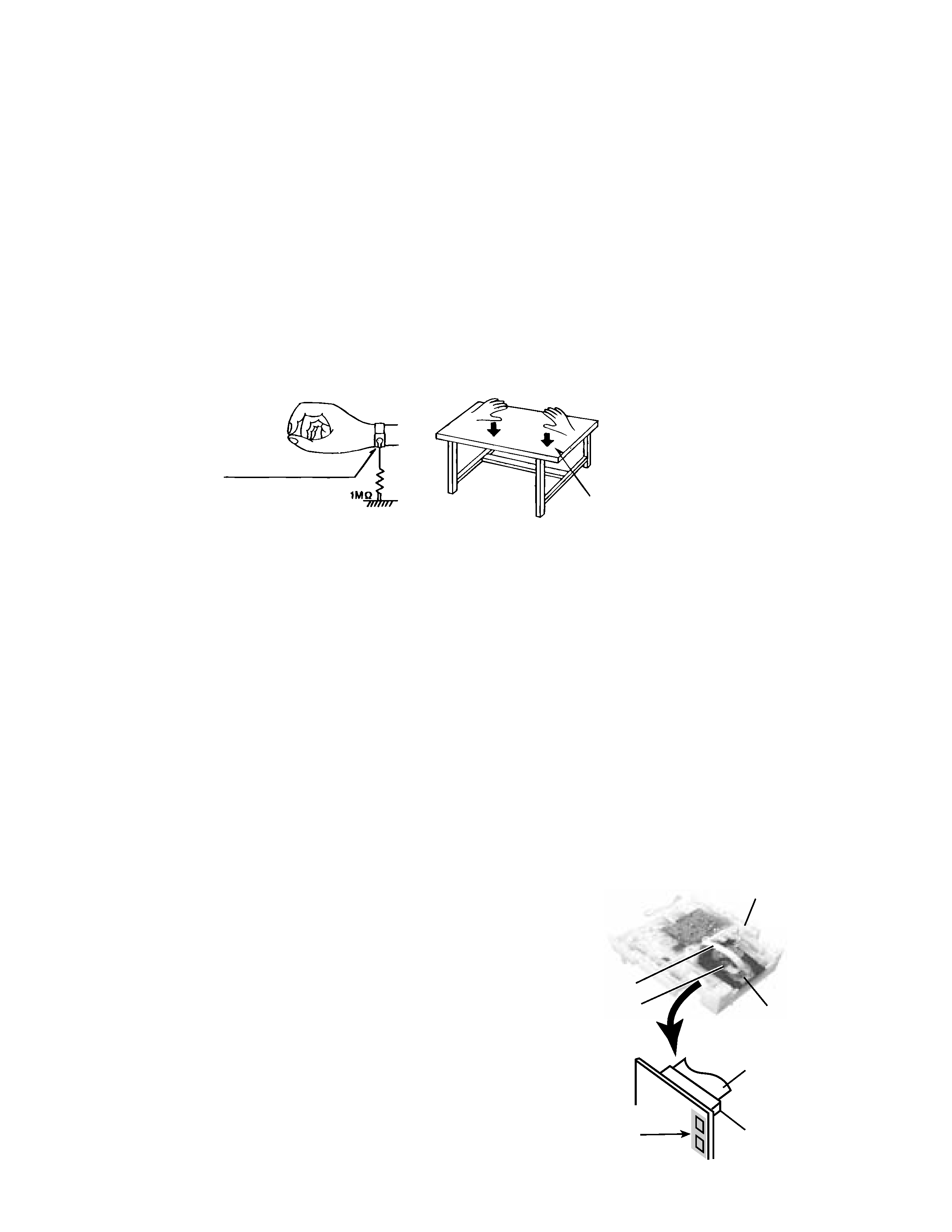
Preventing static electricity
1. Grounding to prevent damage by static electricity
Electrostatic discharge (ESD), which occurs when static electricity stored in the body, fabric, etc. is discharged,
can destroy the laser diode in the traverse unit (optical pickup). Take care to prevent this when performing repairs.
2. About the earth processing for the destruction prevention by static electricity
In the equipment which uses optical pick-up (laser diode), optical pick-up is destroyed by the static electricity of
the work environment.
Be careful to use proper grounding in the area where repairs are being performed.
2-1 Ground the workbench
Ground the workbench by laying conductive material (such as a conductive sheet) or an iron plate over
it before placing the traverse unit (optical pickup) on it.
2-2 Ground yourself
Use an anti-static wrist strap to release any static electricity built up in your body.
3. Handling the optical pickup
1. In order to maintain quality during transport and before installation, both sides of the laser diode on the
replacement optical pickup are shorted. After replacement, return the shorted parts to their original condition.
(Refer to the text.)
2. Do not use a tester to check the condition of the laser diode in the optical pickup. The tester's internal power
source can easily destroy the laser diode.
4. Handling the traverse unit (optical pickup)
1. Do not subject the traverse unit (optical pickup) to strong shocks, as it is a sensitive, complex unit.
2. Cut off the shorted part of the flexible cable using nippers, etc. after replacing the optical pickup. For specific
details, refer to the replacement procedure in the text. Remove the anti-static pin when replacing the traverse
unit. Be careful not to take too long a time when attaching it to the connector.
3. Handle the flexible cable carefully as it may break when subjected to strong force.
4. It is not possible to adjust the semi-fixed resistor that adjusts the laser power. Do not turn it
Conductive material
(conductive sheet) or iron plate
(caption)
Anti-static wrist strap
Attention when CD mechanism assembly is decomposed
1. Remove the CD changer unit.
2. Remove the CD changer mechanism.
3. Solder is put up before the card wire is removed from the pickup unit
connector on the CD mechanism assembly.
(When the card wire is removed without putting up solder, the CD pick-up
assembly might destroy.)
4. Please remove solder after connecting the card wire with the pickup unit
connector when you install picking up in the substrate.
*Please refer to "Disassembly method" in the text for pick-up and how to
detach the CD mechanism assembly.
Soldering
Fig.1
Fig.2
Card wire
Card wire
Picup unit
connector
Picup unit
connector
CD changer unit
CD changer
mechanism
MX-G500
1-5
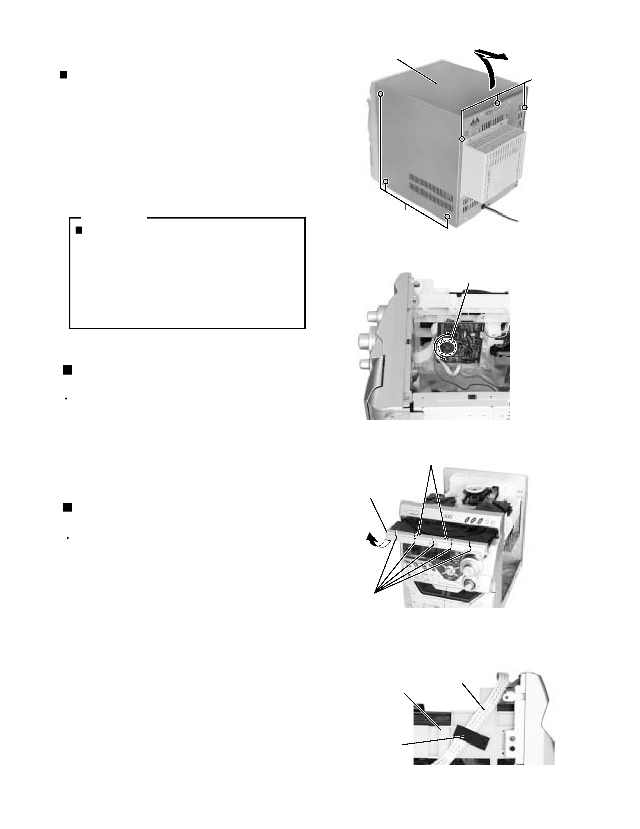
Remove the three screws A attaching the metal
cover on the back of the body.
Remove the six screws B attaching the metal cover
on the both sides of the body.
Remove the metal cover from the body by lifting the
rear part of the cover.
1.
2.
3.
Disassembly method
Removing the metal cover
(See Fig.1)
ONE POINT
How to eject the CD tray
(see fig.2)
Although it will end if the OPEN/CLOSE
button is pushed when a power supply can
be taken, when that is not right, CD tray will
be opened manually.
Turn the loading pulley gear at the bottom of
the CD changer unit as shown in Fig.2 and
draw the CD tray toward the front.
Removing the CD Tray fitting
(See Fig. 3)
Prior to performing the following procedure, eject the
CD tray.
After drawing the lower part of the tray fitting toward
the front, remove the five claws. Then, while moving
the tray fitting upward, remove it.
1.
Prior to performing the following procedure, remove
the metal cover.
Remove the card wire attached to CD changer unit
on the adhesion tape.
Disconnect the card wire from the connector CW107
on the CD servo board.
Disconnect the harness from the connector RCW6
on the main board and CW105 on the CD servo
board.
Remove the two screws C attaching the CD changer
unit to the rear panel.
Remove the two screws D attaching the CD changer
unit to the both side of front panel assembly.
Draw the CD changer unit upward from behind while
pulling the rear panel outward.
1.
2.
3.
4.
5.
6.
Removing the CD changer unit
(See Fig.4 to 7)
Fig.1
Fig.2
Fig.3
Metal cover
A
B
(both sides)
Joint
Claw
CD tray fitting
Loading pulley gear
(See <CD changer unit>fig.1)
Fig.4
CD changer unit
Card wire
Adhesion tape