SERVICE MANUAL
COPYRIGHT © 2003 VICTOR COMPANY OF JAPAN, LTD.
No.G1004
2003/02
MP-XP7220KR,MP-XP5220KR
Mobile mini note PC
G1004
2003
02
MP-XP7220KR,MP-XP5220KR
TABLE OF CONTENTS
1
SPECIFIC SERVICE INSTRUCTIONS . . . . . . . . . . . . . . . . . . . . . . . . . . . . . . . . . . . . . . . . . . . . . . . . . . . . . . 1-2
1.1
Disassembly procedure . . . . . . . . . . . . . . . . . . . . . . . . . . . . . . . . . . . . . . . . . . . . . . . . . . . . . . . . . . . . 1-2
1.2
Preinstallation procedure . . . . . . . . . . . . . . . . . . . . . . . . . . . . . . . . . . . . . . . . . . . . . . . . . . . . . . . . . . . 1-7
1.3
Caution in exchanging a bottom case . . . . . . . . . . . . . . . . . . . . . . . . . . . . . . . . . . . . . . . . . . . . . . . . . 1-8
1.4
Replace procedure of main board . . . . . . . . . . . . . . . . . . . . . . . . . . . . . . . . . . . . . . . . . . . . . . . . . . . . 1-8
1.5
Operation check item list after the repair is completed . . . . . . . . . . . . . . . . . . . . . . . . . . . . . . . . . . . . 1-9
1.6
Another sales option list . . . . . . . . . . . . . . . . . . . . . . . . . . . . . . . . . . . . . . . . . . . . . . . . . . . . . . . . . . . . 1-9
Area Suffix
KR ------------------
Korea
MP-XP7220KR,MP-XP5220KR
1-2 (No.G1004)
SECTION 1
SPECIFIC SERVICE INSTRUCTIONS
1.1 Disassembly procedure
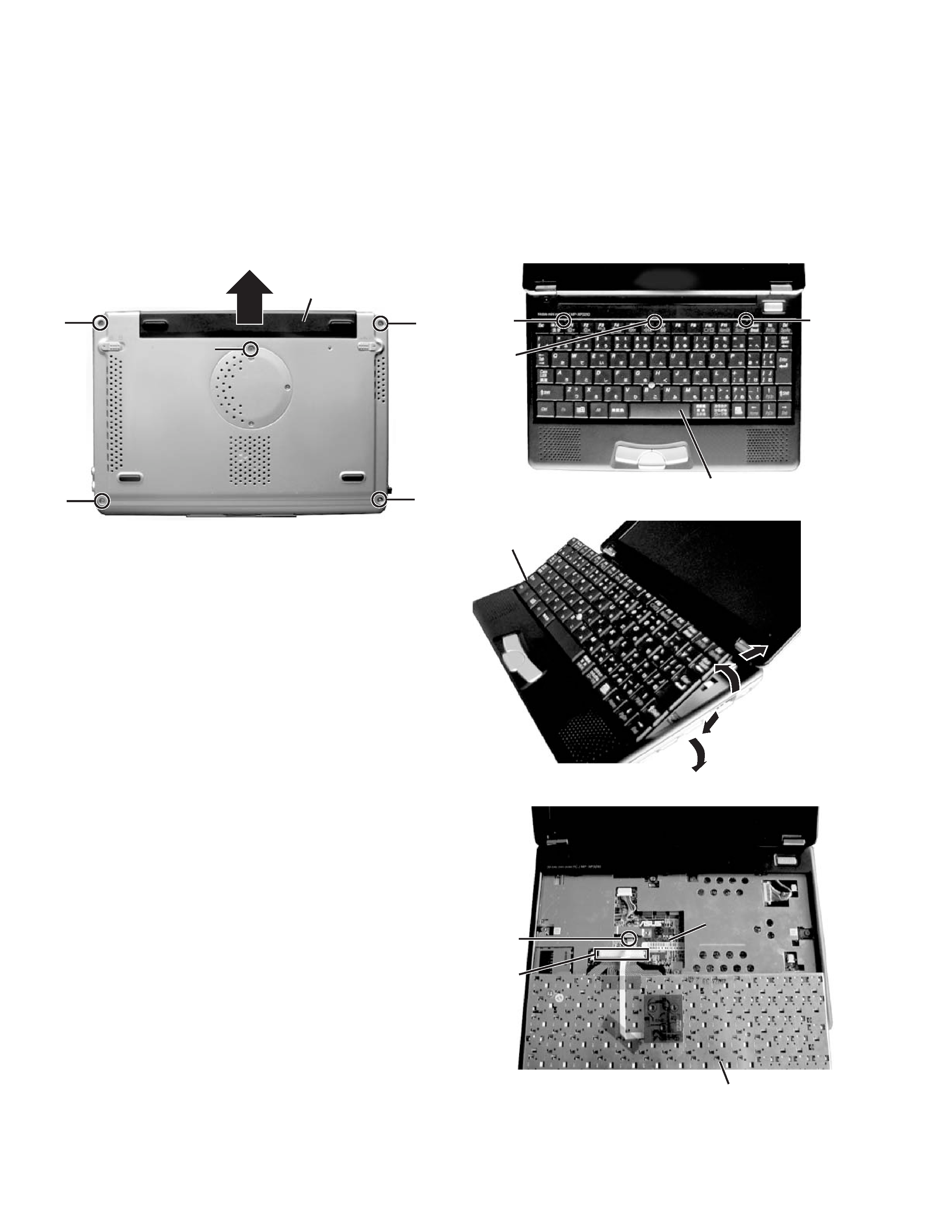
1.1.1 Removing the internal battery
(See Figure 1)
Prior to performing the following procedure, remove the external
battery.
(1) Remove one screw A on the bottom of the main body.
(2) Pull out the internal battery in the rear direction.
Fig.1
1.1.2 Removing the keyboard assembly
(See Figure 2 ~ Figure 4)
(1) Push the three latches (a) in the upper part of the keyboard
with a single-slotted screwdriver or a flat screwdriver, and
lift the keyboard.
(2) Disconnect the wires from connectors CN4 and CN1 on the
mother board respectively.
Fig.2
Fig.3
Fig.4
E
E
A
E
E
Internal battery
Bottom
Bottom
Latch a
Latch a
Latch a
Keyboard
Keyboard
In removing
the keyboard
In attaching
the keyboard
2
1
2
2
1
1
CN4
CN1
Keyboard
Mother board
Mother board
Mother board
MP-XP7220KR,MP-XP5220KR
(No.G1004)1-3
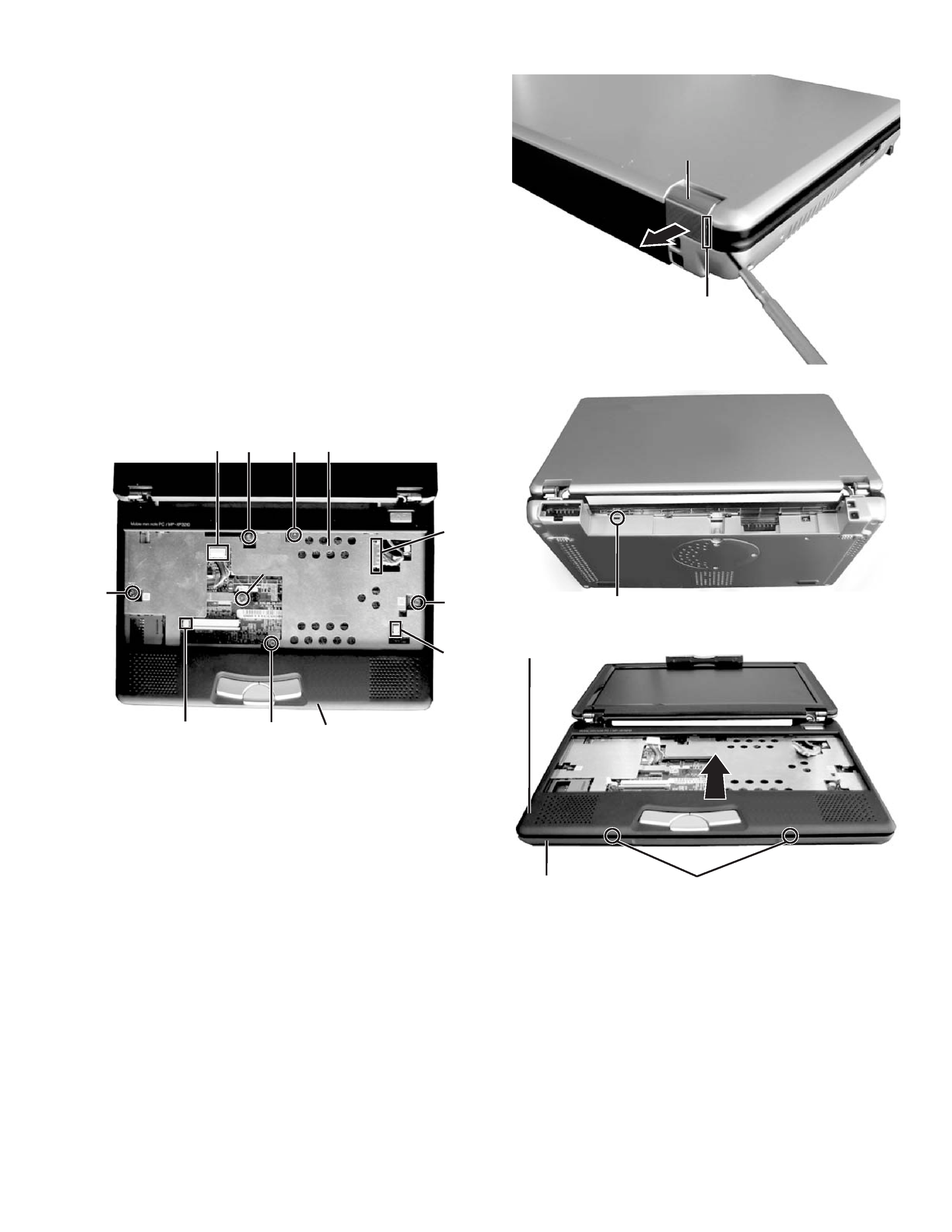
1.1.3 Removing the top case and LCD panel assembly (See
Figure 1 and Figure 5 ~ Figure 8)
· Prior to performing the following procedure, remove the key-
board assembly.
(1) Insert a single-slotted screwdriver or a flat screwdriver in a
space b on the underside of the hinge cover. Then, remove
the hinge cover by pulling the screwdriver in the direction
indicated by the arrow.
And then, remove one more hinge cover at the other side
of the main body.
(2) Remove the four screws B attaching the top case.
(3) Remove one screw C (short) and one screw D (long) at-
taching the shield plate.
(4) Reverse the main body, and remove the four screws E on
the bottom of the main body. (See Figure 1)
(5) Disconnect the connector wire from the connector CN2 on
the mother board. Similarly, remove the connector wires
from the connectors CN3, CN5, and CN7.
(6) Remove one latch c on the rear side of the main body, and
release the two joints d while moving the top case in the
rear direction.
Fig.5
Fig.6
Fig.7
Fig.8
CN3
B
B
C
B
D
B
CN7
CN5
Top case
CN2
Shield plate
Space b
Hinge cover
Hinge cover
Latch c
Joint d
Bottom case
Top case
MP-XP7220KR,MP-XP5220KR
1-4 (No.G1004)
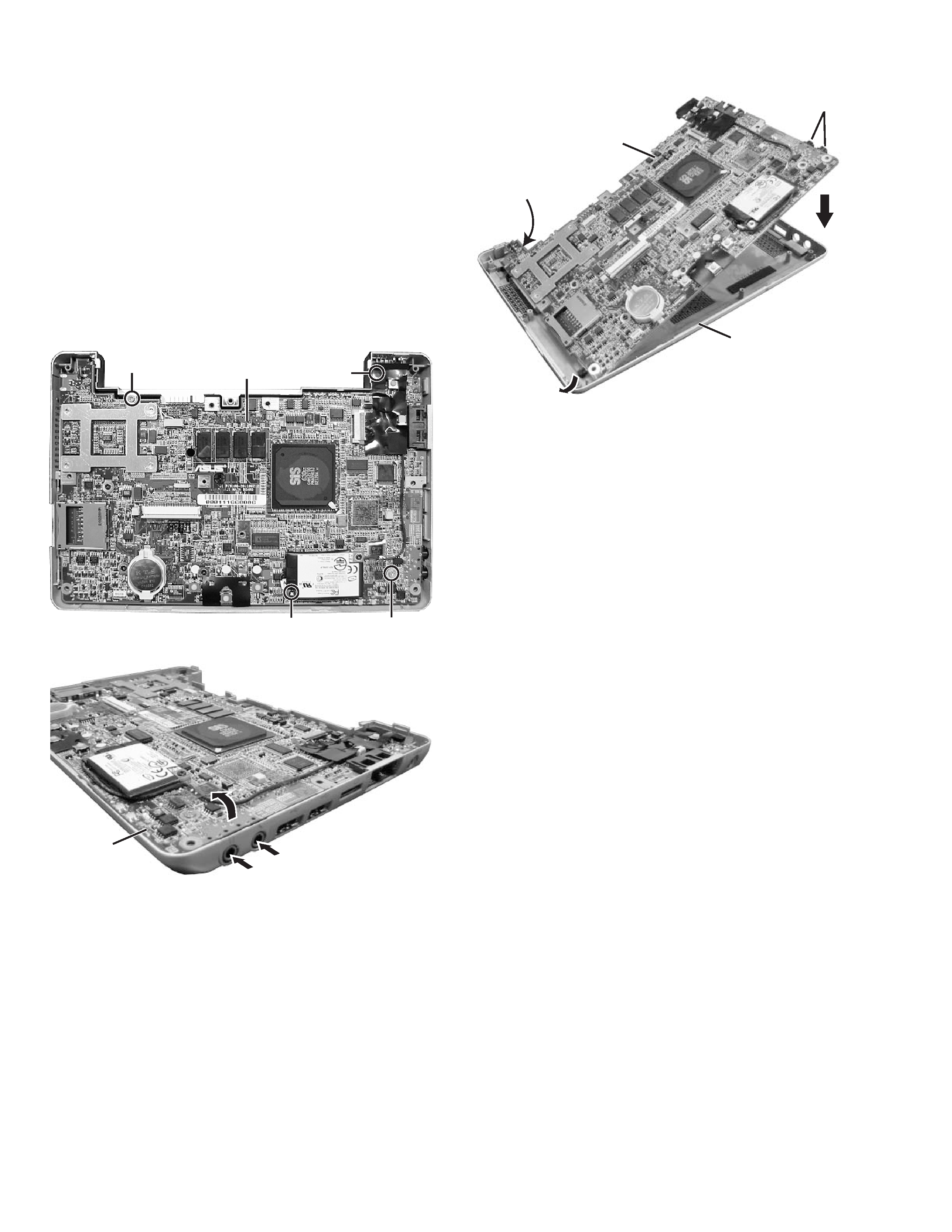
1.1.4 Removing the mother board
(See Figure 9 ~ Figure 11)
· Prior to performing the following procedure, remove the key-
board assembly, the top case, and the LCD panel assembly.
(1) Remove one screw F (short), one screw G (middle), and
the two screws H (long) attaching the mother board.
(*In attaching the mother board, tighten H1, H2, G, and F
in this order.)
(2) Lift the mother board while pushing the microphone and
headphone jack in the direction indicated by the arrow, and
remove the mother board.
*Be careful not to damage the battery detector switch on
the backside of the mother board.
* In attaching the mother board, put the lever of the PCMCIA slot
through the bottom case, and then push and attach the micro-
phone and headphone jack.
Fig.9
Fig.10
Fig.11
Caution
In attaching the mother board to the bottom case or in attach-
ing the top case to the bottom case, soft workbench must not
be used because it may distort the bottom case and the top
case. Attachment operation must be performed on workbench
hard enough.
G
F
H
1
H
2
Mother board
Microphone and
headphone jack
2
2
1
1
Mother board
Microphone and
headphone jack
2
2
1
1
Mother board
Battery detector
switch
Bottom case
MP-XP7220KR,MP-XP5220KR
(No.G1004)1-5
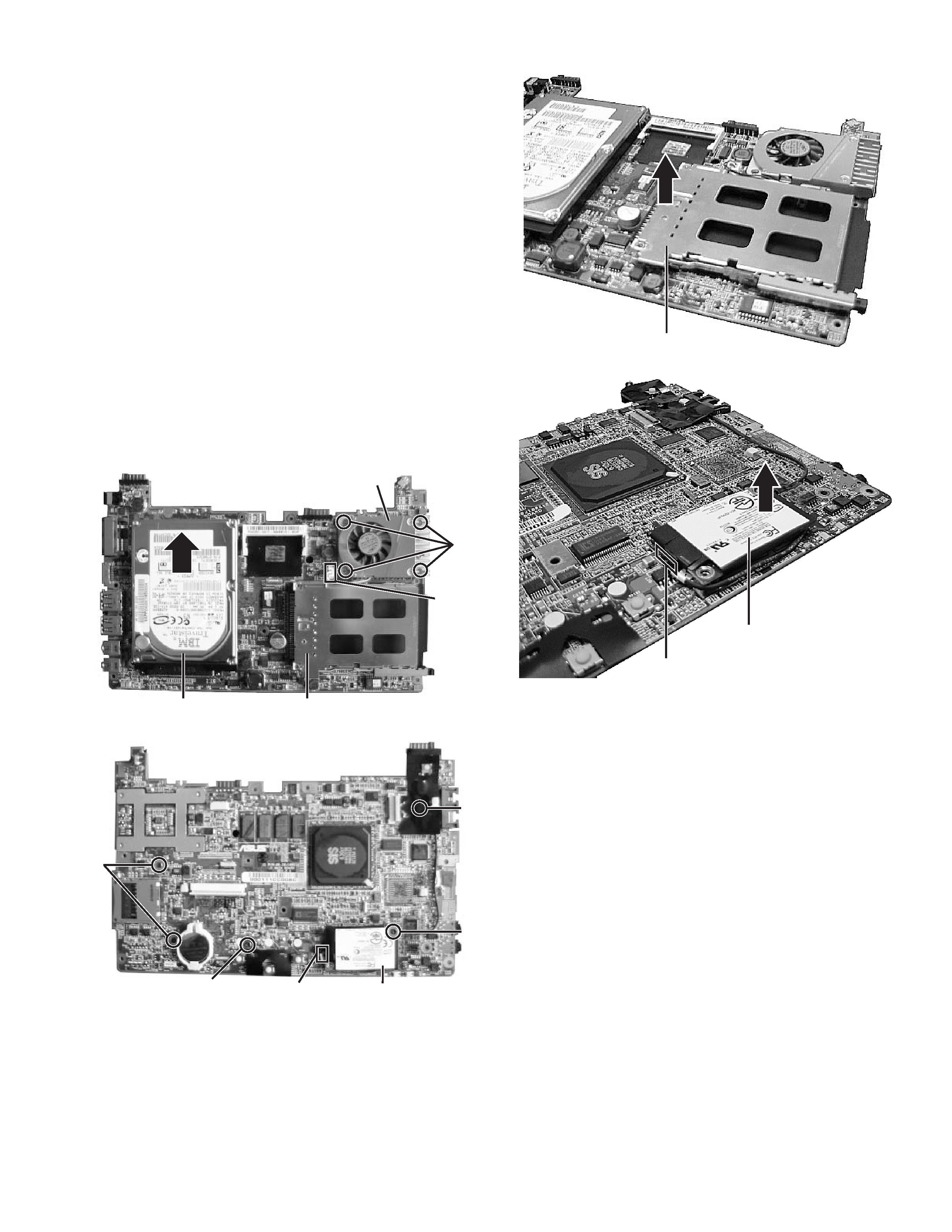
1.1.5 Removing the parts on the mother board
(See Figure 12 ~ 15)
· Prior to performing the following procedure, remove the moth-
er board.
*Removing the fan assembly
(1) Remove the four screws I attaching the fan assembly.
(2) Disconnect the connector wire from the connector CN13 on
the mother board.
*Removing the hard disc drive
(1) Remove one screw J at the side of the mother board where
the hard disc drive is not attached.
(2) Remove the hard disc drive by moving the hard disc drive
in the direction indicated by the arrow.
*Removing the PCMCIA slot
(1) Remove one screw K (long) and the two screws L (short)
at the side of the mother board where the PCMCIA slot is
not attached.
(2) Hold and lift the connector side of the PCMCIA slot, and re-
move the PCMCIA slot.
*Removing the modem pack
(1) Remove one screw M attaching the modem pack.
(2) Pull out the socket wire connected to the modem pack.
(3) Lift the modem pack, and remove it.
Fig.12
Fig.13
Fig.14
Fig.15
I
CN13
Fan assembly
Hard disc drive
PCMCIA slot
J
M
L
K
Socket wire
Modem pack
PCMCIA slot
Modem pack
Socket