MC-R433U
LST0122-001A
MC-R433U
DVD-RAM/R
DRIVE
INSTRUCTIONS
Thank you for purchasing the JVC MC-R433U DVD-RAM/R DRIVE.
Before you start operating this unit, please read the instructions
carefully in order to obtain the best possible performance.
For Customer Use:
Enter below the Model No. and Serial
No. which are located at the top of the
unit. Retain this information for future
reference.
Model No. MC-R433U
Serial No.
nted in Japan
T0122-001A
This instruction book is made from 100% recycled paper.
ENGLISH
DEUTSCH
FRANÇAIS
03.7.10, 2:12 PM
3
E
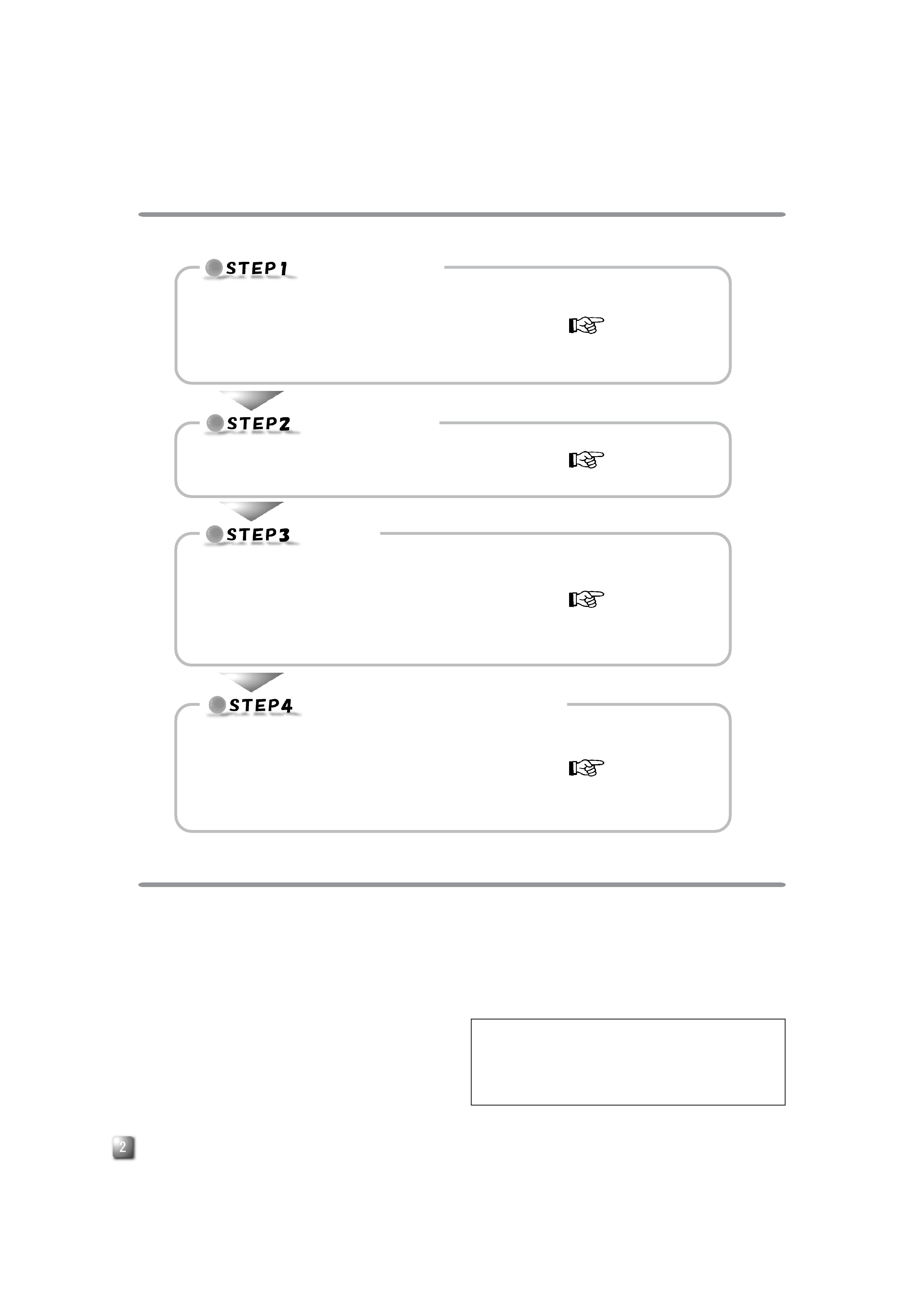
INSTALLATION FLOW
Follow the steps below for installation.
PRECAUTIONS BEFORE USE
INSTALLATION
Page 3
Install the MC-R433U in the CD/DVD Library.
Procedure for Opening the Door of the CD/DVD Library
Procedure for Opening the Drive Storage Cover of the
CD/DVD Library
Procedure for Determining the Setup Position for the MC-R433U
Procedure for Installing the MC-R433U in the CD/DVD Library
CONNECTION
Page 4
Connect the MC-R433U to the CD/DVD Library.
Procedure for Attaching the Provided SCSI Cable
Procedure for Connecting the Cables to the Back of the MC-R433U
SETUP
Page 5
Set the SCSI ID of the MC-R433U and close the door of the CD/
DVD Library.
Procedure for Setting the DIP Switch
Procedure for Setting the Slide Switch
Procedure for Attaching the Drive Storage Cover of the CD/DVD
Library
Procedure for Closing the CD/DVD Library Door
EXECUTION OF AUTOMATIC
DRIVE DETECTION MODE.
Page 6
Execute the automatic drive detection mode and connect the host
computer.
Procedure for Executing the Automatic Drive Detection Mode of
the CD/DVD Library
Procedure for Connecting the CD/DVD Library to the Host Com-
puter
If six drives are installed in the CD/DVD Library and it is re-
quired to connect the MC-R433U units to three or more of
those drives, please consult your dealer or JVC-authorized
service agent.
When six MC-R433U units are installed in the CD/DVD Li-
brary, use the CD/DVD Library at an ambient temperature of
between 5°C to 30°C.
1. DANGER: Invisible laser radiation will occur if the unit is
open due to a failed or defective interlocking device.
2. CAUTION: Do not open the top cover. There are no user
serviceable parts inside the unit; leave all servicing to
qualified service personnel.
The MC-R433U is a DVD-RAM/R drive designed for use with
the JVC MC-8100U/8200U/8600U "CD/DVD Library".
When installing this unit in a Library that is being used, please
read the instruction manual carefully.
The MC-R433U cannot be operated on its own.
This unit cannot be used in combination with the following
models.
· CD-ROM Library : MC-1000 series/2000 series
· DVD-RAM Library: MC-7000 series
For the compatible discs, see the Specifications on page 8.
Before using this unit, be sure to replace the ROM for the
"CD/DVD Library" with the ROM provided with this unit.
For information on firmware version upgrades and replace-
ment of ROMs, please consult the retailer of the MC-R433U
or JVC service agency.
03.7.10, 2:11 PM
2
E
ENGLISH
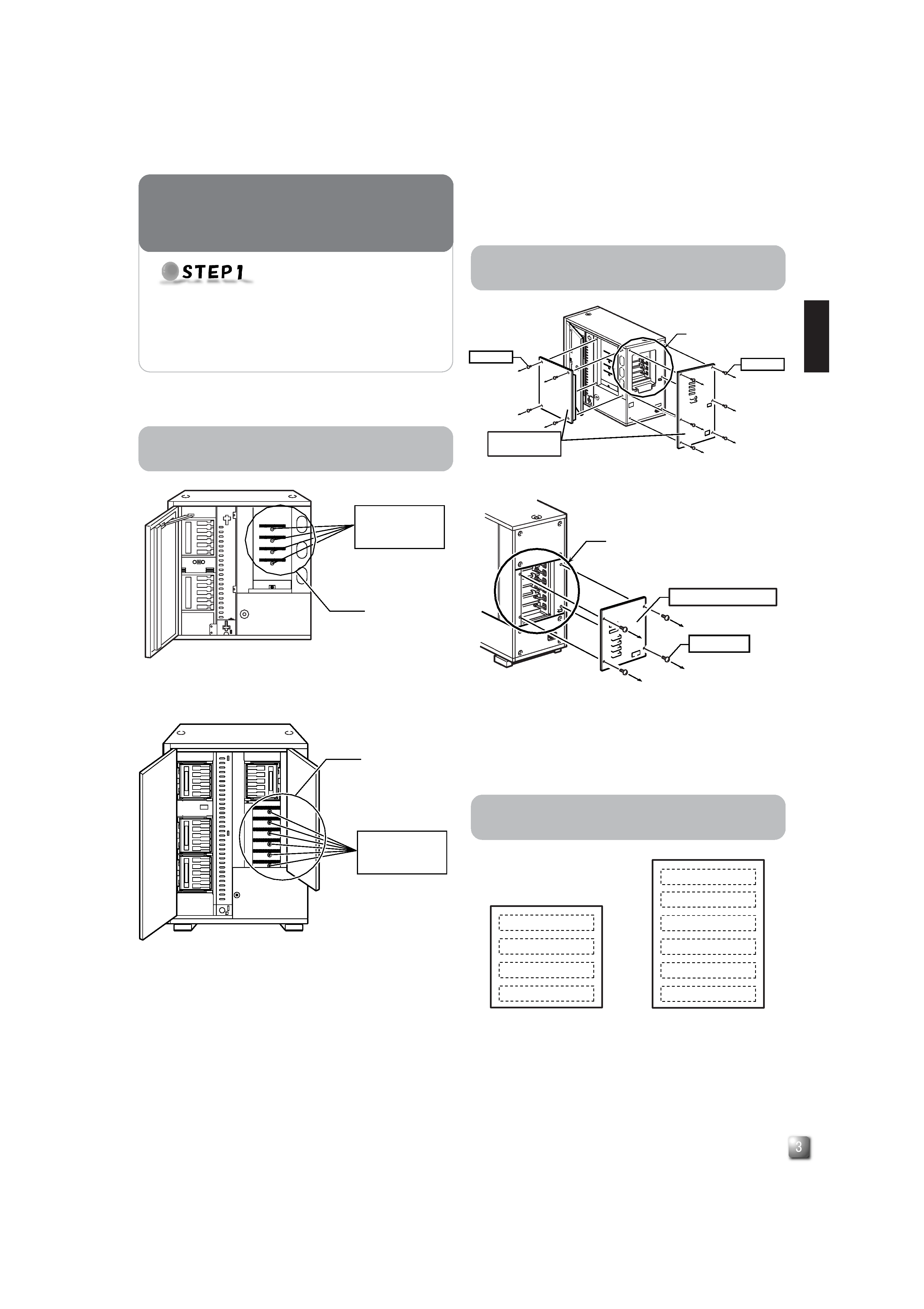
1. Select the [DOOR OPEN MODE] on the MENU screen of
the CD/DVD Library's LCD.
2. Press and hold the "SELECT" switch for five seconds.
3. Turn off the power of the CD/DVD Library when [THE DOOR
CAN BE OPENED] message is displayed on the LCD.
4. Insert the key in the key cylinder located at the center of
the door to unlock and open the door.
* The illustration shows the CD/DVD Library with the drive storage
cover removed for ease of description.
<With the MC-8100U>
<With the MC-8200U>
1. Remove the screws from the drive storage cover of the
CD/DVD Library.
2. Remove the drive storage cover.
1. Install the drives to the drive slots No.1 through No.6 (No. 1
through No. 4 in the case of the MC-8100U) sequentially.
It makes the work easy if the drives are installed from
the lowest number to the highest.
<MC-8100U drive storage section> <MC-8200U drive storage section>
Install the MC-R433U in the CD/DVD Library.
Before starting installation, be sure to turn both the
host computer and peripherals off.
For information related to the CD/DVD Library, refer
to the instruction manual for the CD/DVD Library.
INSTALLATION
<With the MC-8100U>
<With the MC-8200U>
Drive locking
screw mounting
hole
Drive storage
section
Drive storage
section
Drive locking
screw mounting
hole
Drive No. 3
Drive No. 4
Drive No. 1
Drive No. 2
Drive No. 6
Drive No. 3
Drive No. 4
Drive No. 5
Drive No. 1
Drive No. 2
Screw
Screw
Drive storage
section
Drive storage
cover
Drive storage
section
Screw
Drive storage cover
Procedure for Opening the Door of the
CD/DVD Library
Procedure for Opening the Drive Storage
Cover of the CD/DVD Library
Procedure for Determining the Setup
Position for MC-R433U
03.7.10, 2:12 PM
3
E
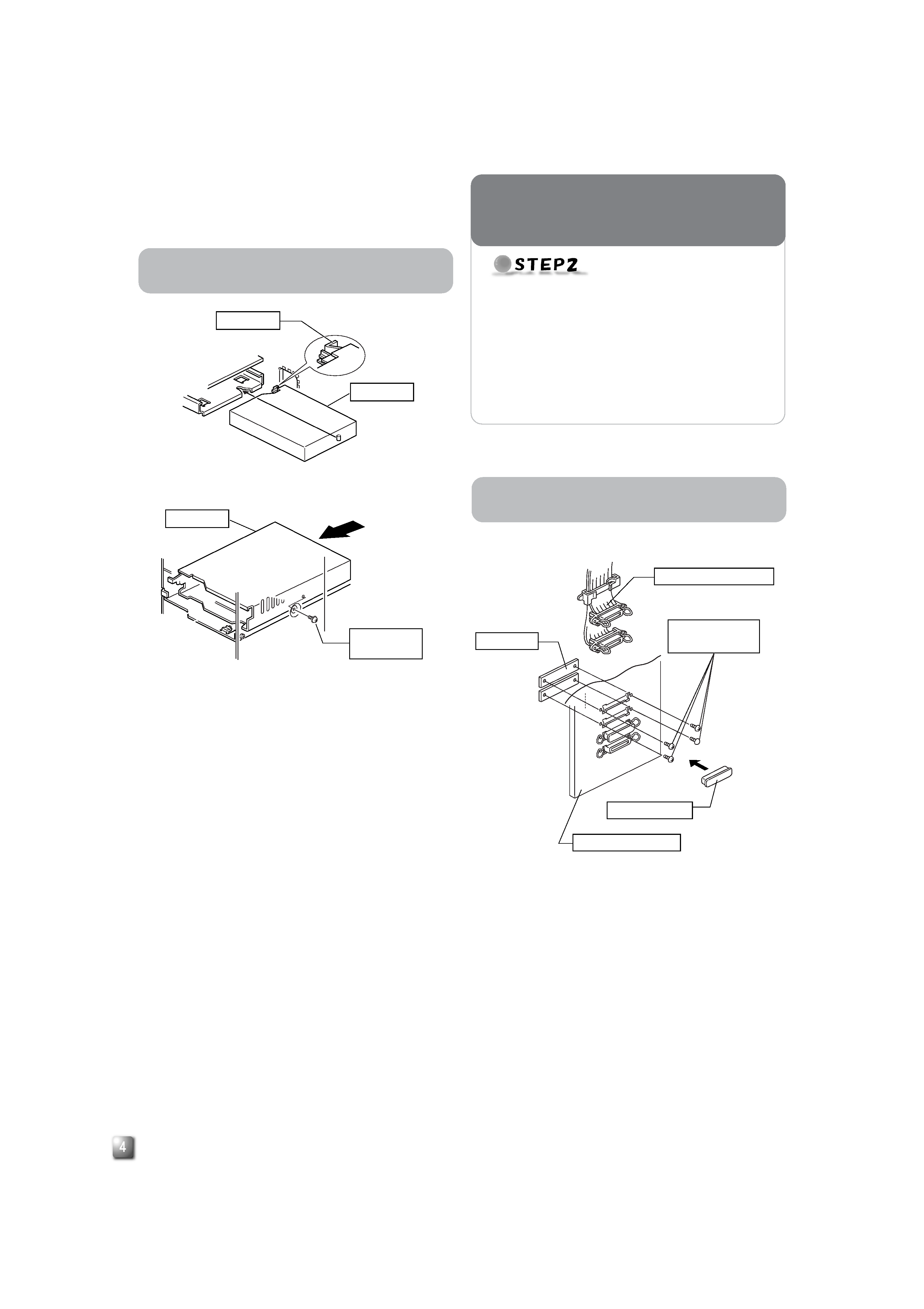
1. In order to remove the two blind plates, remove the four
screws from the SCSI connector installation section at the
rear of the CD/DVD Library (drive storage cover).
2. Insert the provided SCSI cable through the installation hole
from the inside of the drive storage cover and secure it with
the four screws.
Remove the connector cap of the SCSI cable for instal-
lation.
Be sure that the SCSI connector is inserted in the cor-
rect direction. (It should be the same as the direction of
the SCSI connector "SCSI-A.")
3. If the cable or the terminator are not being connected to
the OUT side of the SCSI connector ("SCSI-D"), place the
connector cap over it.
1. Insert the MC-R433U from the rear of the CD/DVD Library
Be sure not to damage the sensor slit.
Make sure that the direction of the MC-R433U is correct
when inserting it.
Be sure that the cables connected to the rear of the CD/
DVD Library are not caught or pinched when inserting
the MC-R433U.
2. Insert the MC-R433U slowly until the screw installation hole
located on the side of the MC-R433U and the screw instal-
lation hole located on the drive locking section are aligned.
3. Screw in the provided drive locking screw to the screw in-
stallation hole of the drive locking section.
Tighten the screw firmly.
If the drive locking screw is loose, the drive and/or Li-
brary may be damaged.
Sensor slit
MC-R433U
Drive locking
screw
MC-R433U
<MC-R433U insertion direction>
<MC-R433U locking method>
<Provided SCSI cable connection method>
* If the provided SCSI cable is not used, go to "Procedure for Con-
necting the Cables to the Back of the MC-R433U" on the next
page.
Blind plate
Connector cap
Drive storage cover
Provided SCSI cable
SCSI connector
mounting screw
Procedure for Installing the MC-R433U in
the CD/DVD Library
Procedure for Attaching the Provided
SCSI Cable
Connect the MC-R433U to the CD/DVD Library.
When necessary, two or more SCSI bus channels
may be used by adding the provided SCSI cable.
If the DVD-R is recorded intermittently due to an in-
sufficiency in the recording transfer rate on the SCSI
bus, the recording quality may deteriorate and play-
back malfunctions may occur.
Also refer to the instruction manual for the CD/
DVD Library.
CONNECTION
03.7.10, 2:12 PM
4
E
ENGLISH
<MC-R433U connection example>
1. Connect the power supply cable, control cable and SCSI
cable to the connectors at the rear of the MC-R433U.
When using the MC-8100U, the No. of the cable must
always correspond to the No. of the drive bay to which it
is being connected. If a cable with the wrong number is
connedted, it will lead to the equipment malfunctioning.
When using the MC-8200U/8600U, connect power sup-
ply and control cables, which lead from the side of the
MC-R433U drive bay to the drive.
Insert all connectors firmly.
SCSI cables are connected as a daisy chain connec-
tion. Each connector should be connected to the drive
positions as illustrated in the diagram.
Terminate each point where the SCSI bus is terminated
physically.
· Setting of the built-in terminators
"Procedure for Setting the DIP Switch" on page 5
· Setting of the external terminators:
The use of active terminators is recommended.
1. TERM: Selection of the use of built-in terminators.
When using the built-in terminators:
· With the MC-R433U unit located at a point where
the SCSI bus is physically terminated set its TERM
ON.
· With other MC-R433U units, set their TERMs to OFF.
When not using the built-in terminators:
· Attach external terminators to the OUT terminals of
the SCSI connector.
· When using an external terminator, set all of the
TERMs of the MC-R433U to OFF.
To improve the stability of SCSI bus communications, it
is recommended to use an active external terminator.
2. ID2, ID1, ID0: Setting of the SCSI ID No. of each drive.
When setting the SCSI ID No., use a number that is not
being used by other SCSI devices on the same bus.
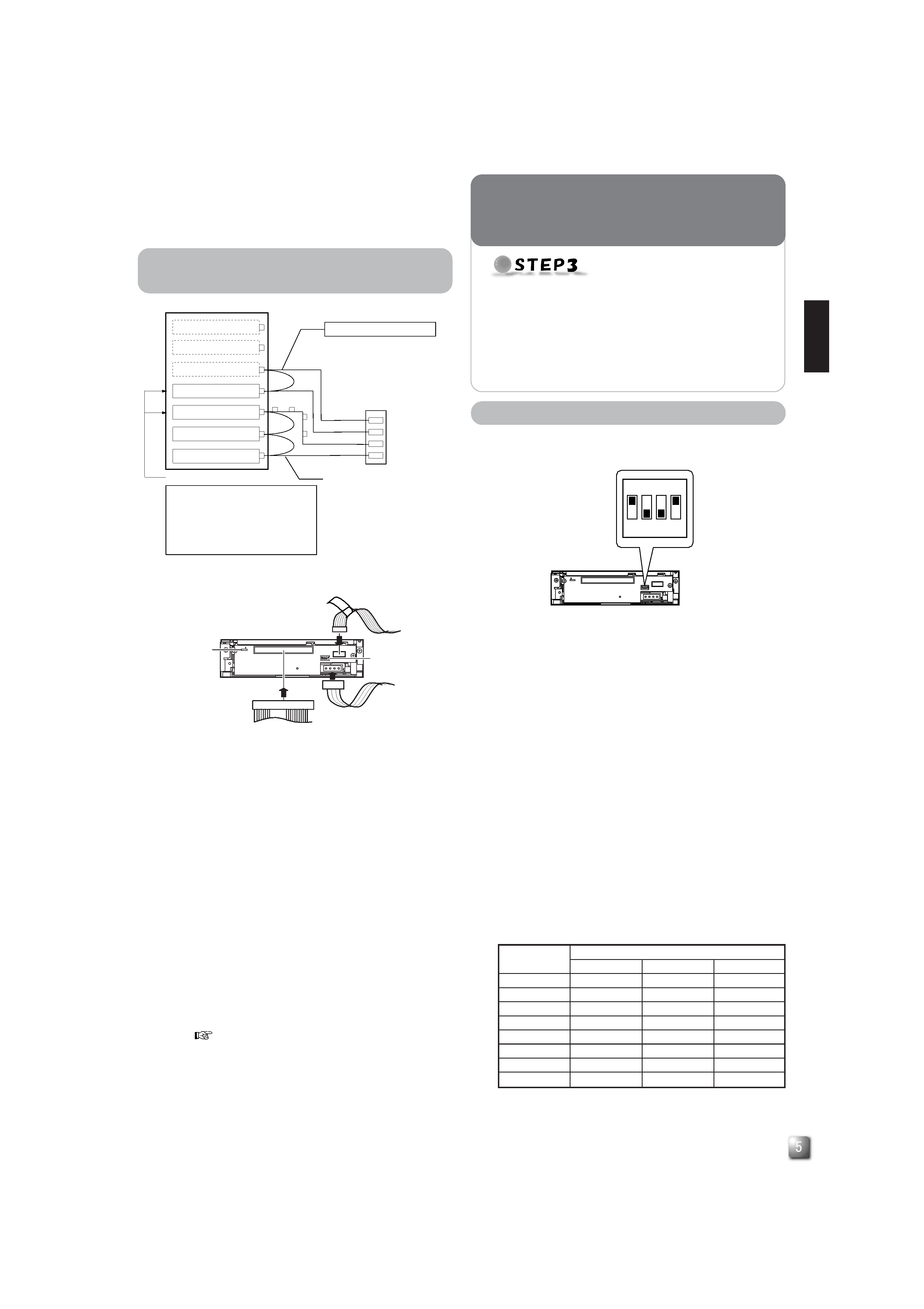
<MC-R433U rear panel>
<MC-R433U DIP switch settings on the rear panel>
DVD-RAM/R drive
Library SCSI board
DVD-RAM/R drive
DVD-RAM/R drive
(Terminate.)
SCSI connector terminals
OUT 2 :Active terminator connected.
IN 2
:Connected to the host computer's
SCSI host adapter No. 2.
OUT 1 :Active terminator connected.
IN 1
:Connected to the host computer's
SCSI host adapter No. 1.
SCSI cable (Additional)
* Up to two DVD-RAM/R drives can
be connected.
SCSI cable (Standard)
Up to 6*1 drives can be connected.
(*
1: Up to 4 with the MC-8100.)
SCSI-B
SCSI-D(F)
SCSI-C(E)
SCSI-A
OUT 2
OUT 1
IN 1
IN 2
SCSI connector
Procedure for Setting the DIP Switch
Set the SCSI ID of the MC-R433U and close the door
of the CD/DVD Library.
Always turn the power of the CD/DVD Library off when
the dip switches are moved.
For the details of the default factory settings, please
refer to the section "SCSI ID No. SETTING" of the
instructions from the CD/DVD Library.
SETUP
<SCSI ID No. and DIP switch settings>
*:Factory setting.
SCSI ID No.
Switch
ID2
ID1
ID0
0
OFF
OFF
OFF
1*
OFF
OFF
ON
2
OFF
ON
OFF
3
OFF
ON
ON
4ON
OFF
OFF
5ON
OFF
ON
6ON
ON
OFF
7ON
ON
ON
WN
Power cable
Control cable
Slide switch
DIP switch
SCSI cable
14p
3
4p
2
3
1
NW
ON
OFF
(Factory setting)
TERM
ID
2
ID
1
ID
0
ON
1234
Procedure for Connecting the Cables to
the Back of the MC-R433U
03.7.10, 2:12 PM
5