SERVICE MANUAL
COPYRIGHT © 2004 Victor Company of Japan, Limited
No.YA179B
2004/9
LCD FLAT TELEVISION
YA179B
2004
9
LT-26X575/KA,
LT-26X585/KA
Supplementary
Here is some information related to the exchange of LAMP UNIT in the LCD PANEL UNIT.
For details other than those described in this manual, please refer to the LT-26X575/KA and LT-26X585/KA
service manual (No.YA179, 2004/8).
BASIC CHASSIS
FL
1-2 (No.YA179B)
SECTION 3
DISASSEMBLY
3.1
DISASSEMBLY PROCEDURE
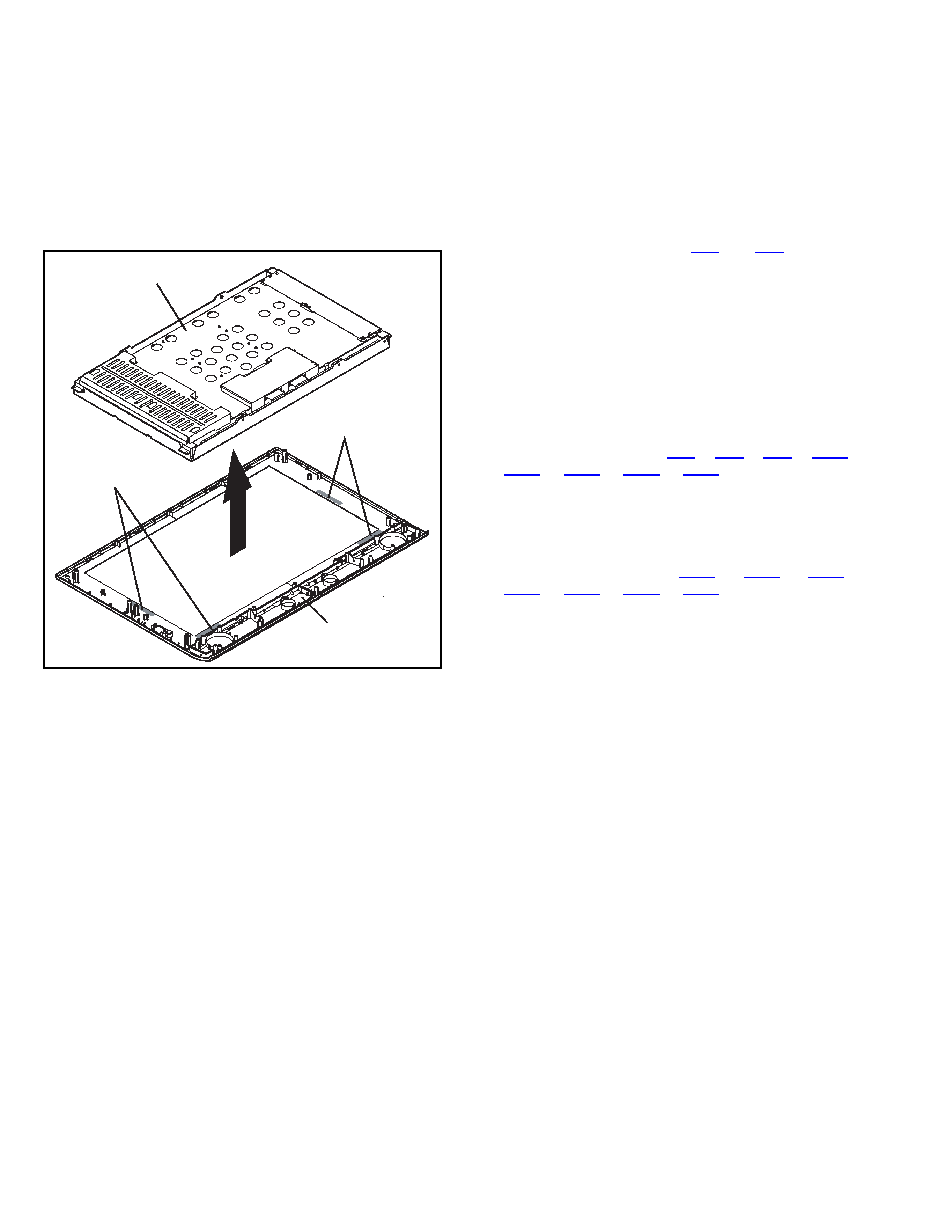
3.1.1 CAUTION ON REMOVING THE LCD PANEL UNIT
The LCD PANEL is fixed to the FRONT PANEL (at the back side)
by using double-side adhesive tapes. To remove the LCD
PANEL UNIT, remove the adhesive tape on the FRONT PANEL
slowly.
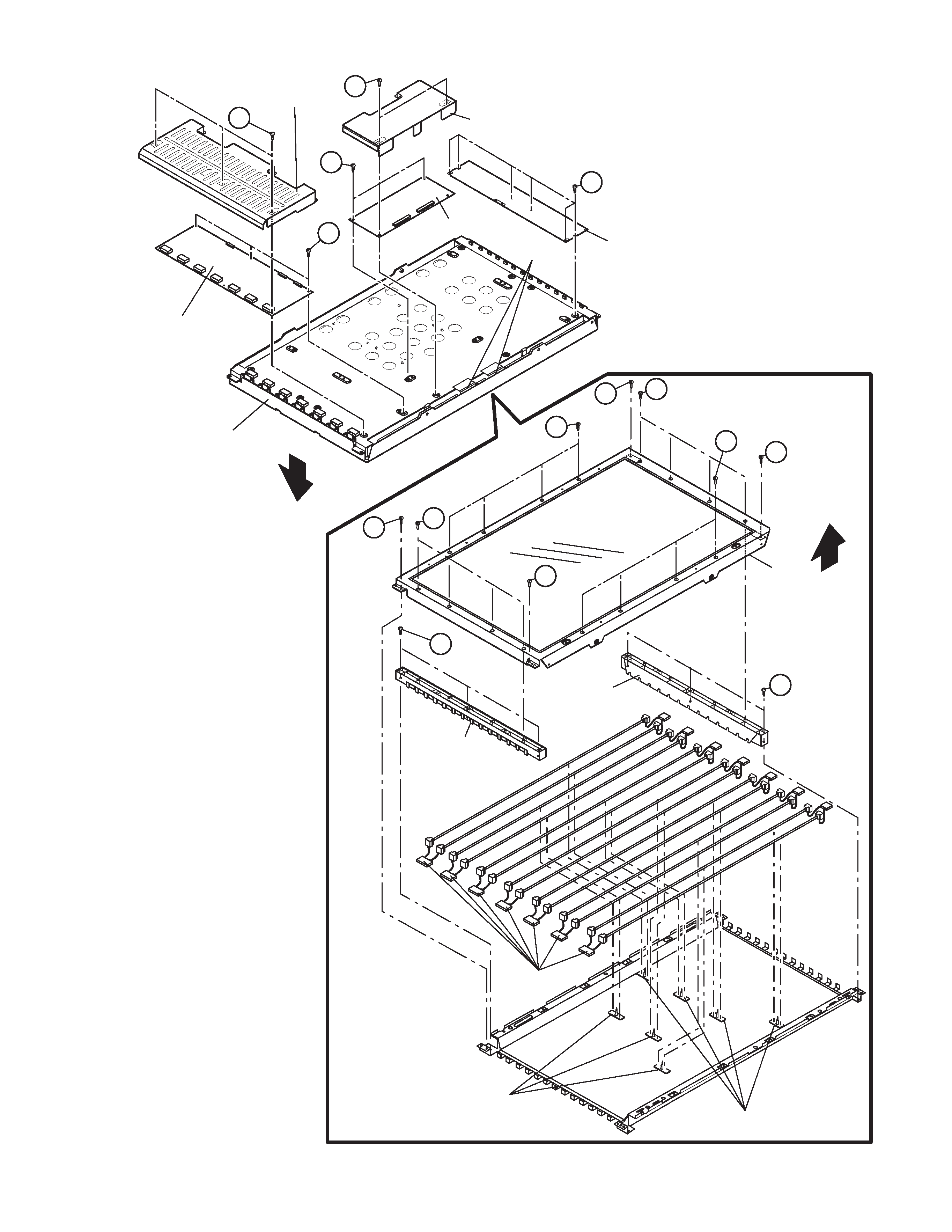
3.1.2 REMOVING THE CONTROL PWB (Fig.1)
· Remove the STAND.
· Remove the REAR COVER.
· Remove the LCD PANEL UNIT.
(1) Remove the 2 screws [A], then remove the CONTROL
PWB COVER.
(2) Disconnect the connector [CN4] / [CN5] from the
CONTROL PWB .
(3) Remove the 2 screws [B], then remove the CONTROL
PWB.
3.1.3 REMOVING THE INVERTER PWB (Fig.1)
· Remove the STAND.
· Remove the REAR COVER.
· Remove the LCD PANEL UNIT.
(1) Remove the 3 screws [C], then remove the INVERTER
PWB COVER.
(2) Disconnect the connector [CN6] / [CN8] / [CN9] / [CN10] /
[CN11] / [CN12] / [CN13] / [CN14] from the INVERTER
PWB (HOT SIDE).
(3) Remove the 3 screws [D], then remove the INVERTER
PWB (HOT SIDE).
(4) Remove the 6 screws [E], then remove the INVERTER
PWB (GND SIDE).
(5) Disconnect the connector [CN15] / [CN16] / [CN17] /
[CN18] / [CN19] / [CN20] / [CN21] from the INVERTER
PWB (GND SIDE).
3.1.4 REMOVING THE LAMP UINT (Fig.1)
< SYMPTOMS OF DEFECTED LUMP UNIT >
When one of the LAMP UNIT pair (2 LAMPS) die and the
power is supplied, the screen image appears just for a second
then disappears.
· Remove the STAND.
· Remove the REAR COVER.
· Remove the LCD PANEL UNIT.
· Remove the CONTROL PWB.
(1) Remove the FERRITE CORE.
CAUTION:
Carry out the procedure with extra care as the FERRITE
CORE is affixed with double-side adhesive tapes and it
may break if extra force is applied.
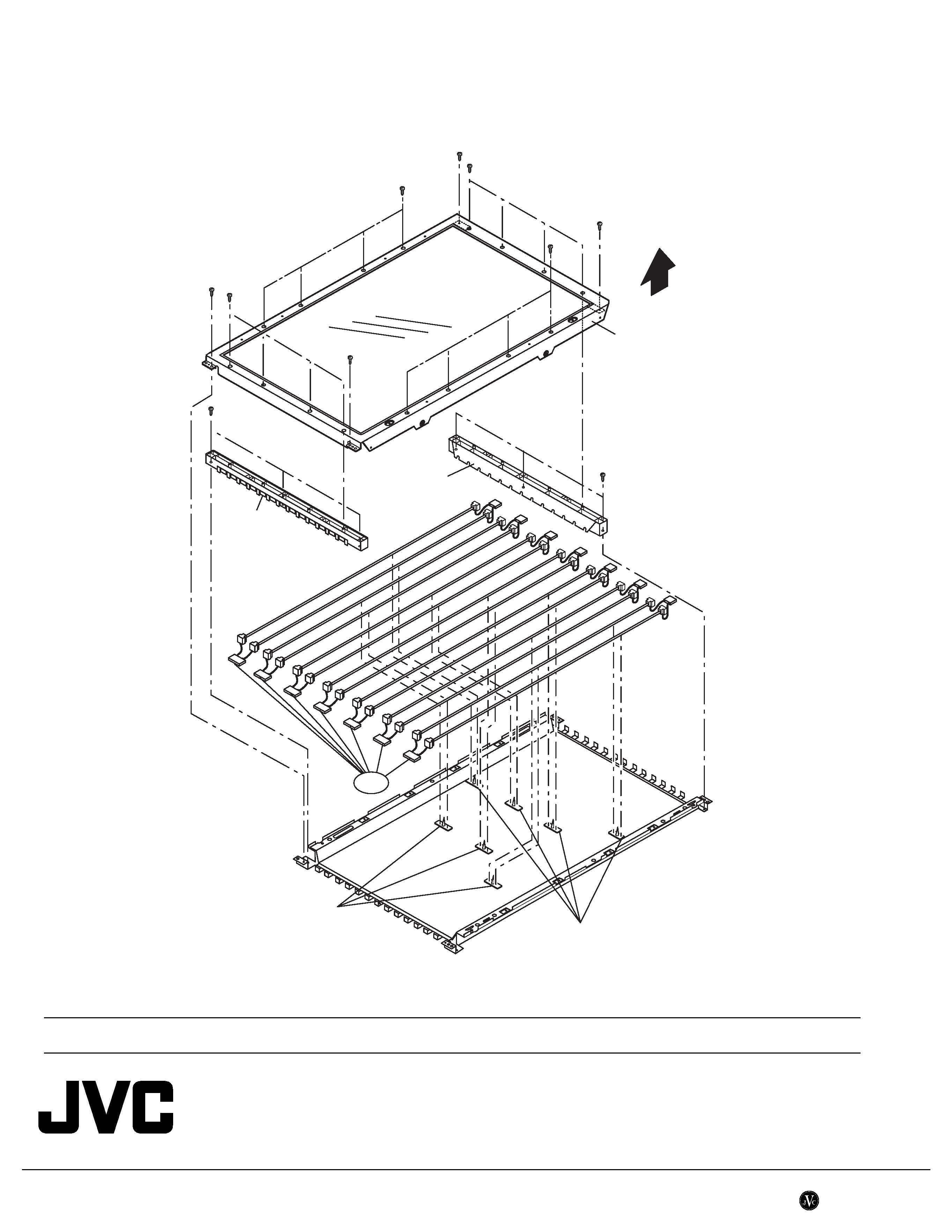
(2) Remove the 4 screws [F], the 8 screws [G] and the 8
screws [H], then remove the PANEL FRAME.
(3) Remove the 6 screws [J], then remove the LAMP
HOLDER.
(4) Remove the LAMP CLIP, then remove the LAMP UINT.
CAUTION ON EXCHAGING THE LAMP UINT
· LAMP UINT is supplied as a pair. After a long period of use,
exchanging only died LAMP may cause the uneven
brightness on the screen as the exchanged LAMP is the
brightest of all. Change all 7 pairs of the LAMP UINT when
exchange is required.
· If the screws that are not specified in this section are
removed, the LCD PANEL will be removed and it cannot be
reassembled.
Double-side adhesive tapes
Double-side adhesive tapes
LCD PANEL UNIT
FRONT PANEL
(No.YA179B)1-3
Fig.1
G
C
A
F
F
H
F
G
E
B
D
H
F
J
J
PANEL FRAME
LCD PANEL UNIT
CONTROL PWB COVER
CONTROL PWB
INVERTER PWB COVER
INVERTER PWB (HOT SIDE)
INVERTER PWB (GND SIDE)
FERRITE CORE
LAMP HOLDER
LAMP HOLDER
LAMP CLIP
LAMP CLIP
LAMP UNIT
FRONT
FRONT
(No.YA179B)
AV & MULTIMEDIA COMPANY VIDEO DISPLAY CATEGORY 12, 3-chome, Moriya-cho, kanagawa-ku, Yokohama, kanagawa-prefecture, 221-8528, Japan
Victor Company of Japan, Limited
WPC
Printed in Japan
PARTS LIST
EXPLODED VIEW
EXPLODED VIEW PARTS LIST
Ref.No.
Part No.
Part Name
Description
Local
150
LQ0DDB5417
LAMP UNIT
2pcs in 1set
PANEL FRAME
LAMP HOLDER
LAMP HOLDER
LAMP CLIP
LAMP CLIP
FRONT
150