SERVICE MANUAL
CD/CASSETTE RECEIVER
No.49729
Apr. 2002
COPYRIGHT
2002 VICTOR COMPANY OF JAPAN, LTD.
KW-XC828
KW-XC828
Area Suffix
U
Ather Areas
Contents
Safety precaution
Disassembly method
Adjustment method
Flow of functional
operation unit TOC read
1-2
1-3
1-30
1-31
Maintenance of laser pickup
Replacement of laser pickup
Description of major ICs
1-33
1-33
1-36
EX
DIRECTORY
SOUND
VOL
VOL
SOURCE
R
F
U
D
ATT
1-2
KW-XC828
! CAUTION Burrs formed during molding may be left over on some parts of the chassis. Therefore,
pay attention to such burrs in the case of preforming repair of this system.
Safety precaution
! CAUTION Please use enough caution not to see the beam directly or touch it in case of an
adjustment or operation check.
1-3
KW-XC828
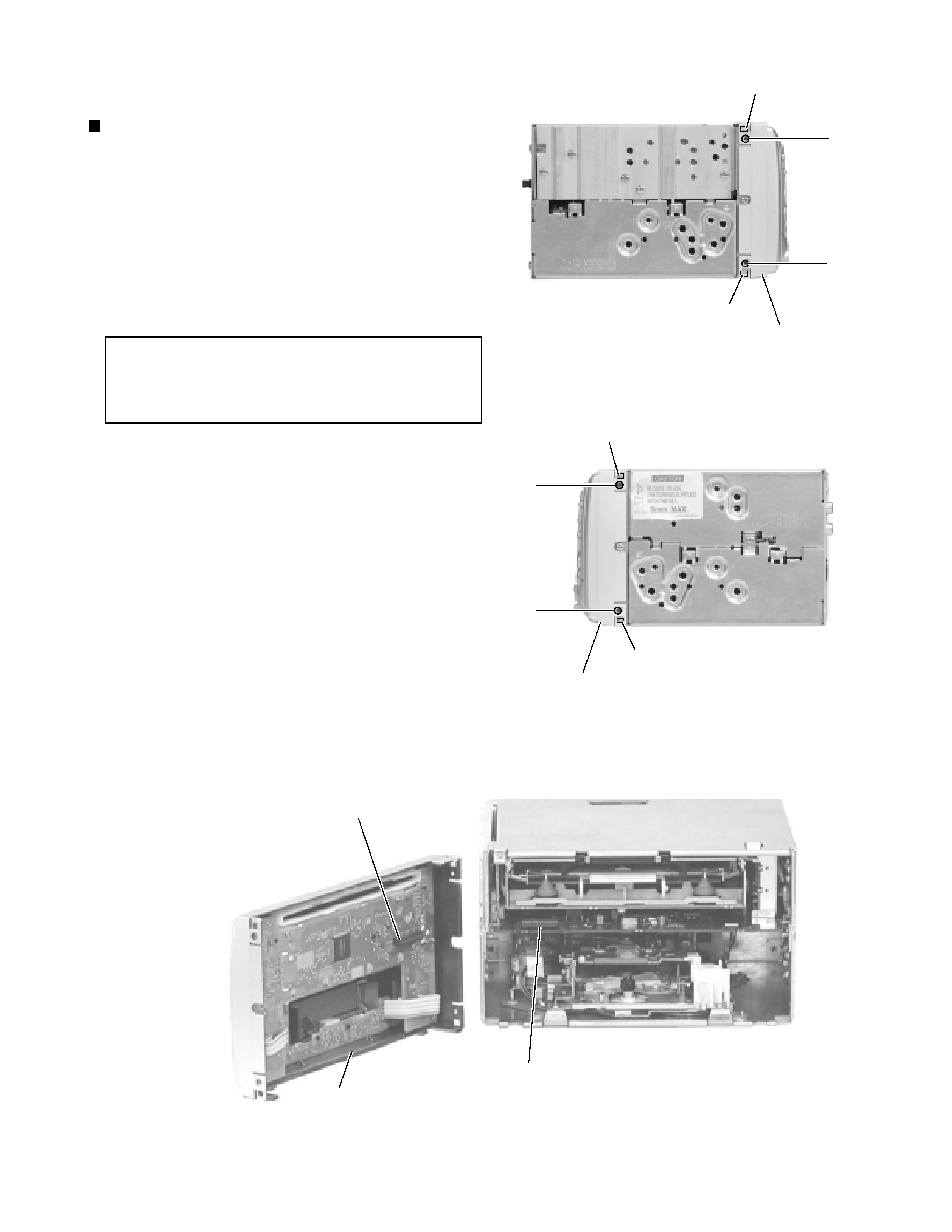
Remove the four screws A
on both sides of the
body.
Release four joints a on both sides of the body using
a screwdriver and remove the front panel assembly
toward the front. The connector which connects the
front panel assembly with the rear section comes off.
1.
2.
Disassembly method
Removing the front panel assembly
(See Fig.1 ~ 3)
When reassembling, make sure that
connector CN501 on the front panel
assembly is securely connected to
CN701 on the main board (See Fig.3).
CAUTION:
A
A
A
A
CN701
CN501
Joint a
Joint a
Front panel assembly
Fig.1
Fig.2
Joint a
Joint a
Front panel assembly
Fig.3
Front panel assembly
1-4
KW-XC828
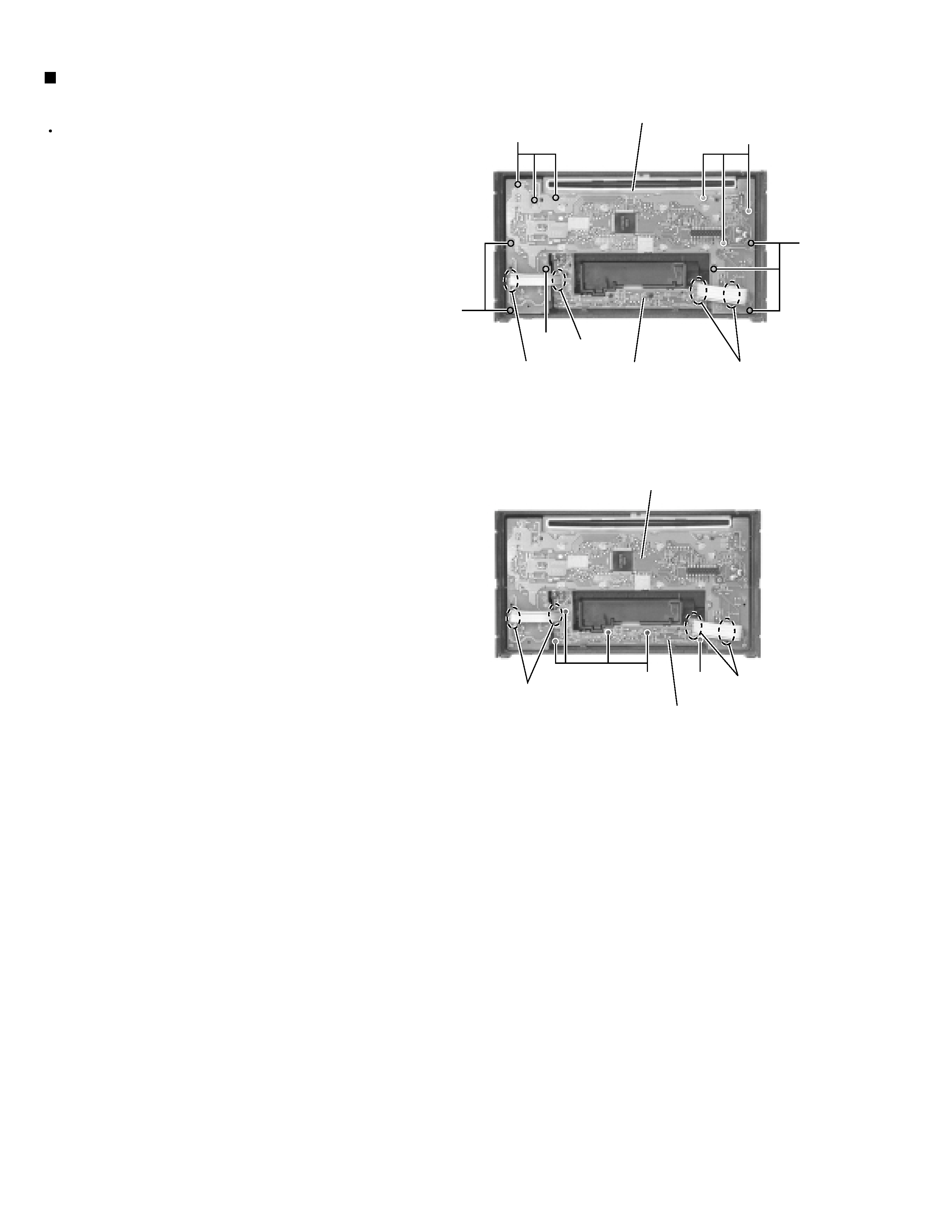
Prior to performing the following procedure, remove
the front panel assembly.
Remove the twelve screws B retaining the system
control board.
Remove the five screws C
retaining the switch
board.
Unsolder
WR501
and
WR502
of
the
wires
connecting the system control board with the switch
board.
1.
2.
3.
Removing the system control board /
switch board (See Fig.4 , 5)
B
B
B
Switch board
Switch board
System control board
CC
B
WR502
WR502
WR501
WR501
WR502
Fig.4
Fig.5
System control board
B
1-5
KW-XC828
Prior to performing the following procedure, remove
the front panel assembly.
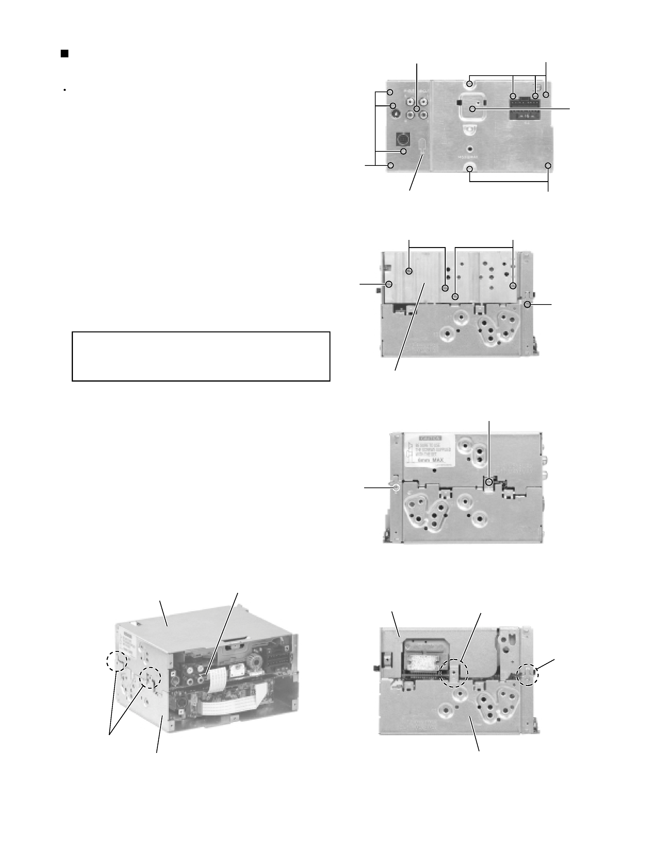
Remove the ten screws D, the screw E
and F
attaching the rear panel on the back of the body.
Remove the three screws G and the two screws H
attaching the heat sink on the left side.
Remove the three screws I attaching the CD player
section and the cassette player section on the both
sides of the body.
Disconnect the card wire from connector CN702 on
the main board in the CD player section on the back
of the body.
Remove the CD player section upward.
1.
2.
3.
4.
5.
Removing
the
CD
player
section
/
cassette player section (See Fig.6 ~ 10)
When reassembling, joint the CD player
section and the cassette player section
at four joints b.
CAUTION:
D
D
E
D
G
G
I
I
I
CN702
CD player section
Cassette player section
Joint b
F
H
Heat sink
Rear panel
Fig.6
Fig.7
Fig.8
Fig.10
Fig.9
Joint b
CD player section
Joint b
Cassette player section