SERVICE MANUAL
COPYRIGHT © 2003 VICTOR COMPANY OF JAPAN, LIMITED
No.49875
2003/6
CASSETTE RECEIVER
49875
2003
6
KS-FX945R
TABLE OF CONTENTS
1
PRECAUTION. . . . . . . . . . . . . . . . . . . . . . . . . . . . . . . . . . . . . . . . . . . . . . . . . . . . . . . . . . . . . . . . . . . . . . . . . 1-3
2
SPECIFIC SERVICE INSTRUCTIONS . . . . . . . . . . . . . . . . . . . . . . . . . . . . . . . . . . . . . . . . . . . . . . . . . . . . . . 1-4
3
DISASSEMBLY . . . . . . . . . . . . . . . . . . . . . . . . . . . . . . . . . . . . . . . . . . . . . . . . . . . . . . . . . . . . . . . . . . . . . . . 1-5
4
ADJUSTMENT . . . . . . . . . . . . . . . . . . . . . . . . . . . . . . . . . . . . . . . . . . . . . . . . . . . . . . . . . . . . . . . . . . . . . . . 1-20
5
TROUBLE SHOOTING . . . . . . . . . . . . . . . . . . . . . . . . . . . . . . . . . . . . . . . . . . . . . . . . . . . . . . . . . . . . . . . . . 1-24
6
DESCRIPTION OF MAJOR ICs . . . . . . . . . . . . . . . . . . . . . . . . . . . . . . . . . . . . . . . . . . . . . . . . . . . . . . . . . . 1-25
SOUND
VOL
VOL
SOURCE
R
F
U
D
ATT
Area Suffix
EE --------- Russian Federation
1-2 (No.49875)
SPECIFICATION
Design and specifications are subject to change without notice.
AUDIO AMPLIFIER
SECTION
Maximum Power
Output
Front
50 W per channel
Rear
50 W per channel
Continuous Power
Output (RMS)
Front
19 W per channel into 4
40 Hz to 20 000 Hz at
no more than 0.8% total harmonic distortion.
Rear
19 W per channel into 4
40 Hz to 20 000 Hz at
no more than 0.8% total harmonic distortion.
Load Impedance
4
(4 to 8 allowance)
Tone Control Range Bass
±10 dB at 100 Hz
Treble
±10 dB at 10 kHz
Frequency Response
40 Hz to 20 000 Hz
Signal-to-Noise Ratio
70 dB
Line-Out Level/Impedance
2.0 V/20 k
load (250 nWb/m)
Output Impedance
1 k
TUNER SECTION
Frequency Range
FM1/FM2
87.5 MHz to 108.0 MHz
FM3
65.00 MHz to 74.00 MHz
AM
(MW) 522 kHz to 1 620 kHz (LW) 144 kHz to 279
kHz
[FM Tuner]
Usable Sensitivity
11.3 dBf (1.0
V/75 )
50 dB Quieting Sensitivity
16.3 dBf (1.8
V/75 )
Alternate Channel Selectivity (400 kHz) 65 dB
Frequency Response
40 Hz to 15 000 Hz
Stereo Separation
30 dB
Capture Ratio
1.5 dB
[MW Tuner]
Sensitivity
20
µV
Selectivity
35 dB
[LW Tuner]
Sensitivity
50
µV
CASSETTE DECK
SECTION
Wow & Flutter
0.11% (WRMS)
Fast-Wind Time
100 sec. (C-60)
Frequency Response (Dolby B NR OFF)
30 Hz to 16 000 Hz (Normal tape)
Signal-to-Noise Ratio
56 dB (Normal tape)
(Dolby B NR ON)
65 dB
(Dolby B NR OFF)
56 dB
Stereo Separation
40 dB
GENERAL
Power Requirement Operating Voltage
DC 14.4 V (11 V to 16 V allowance)
Grounding System
Negative ground
Allowable Operating Temperature
0ºC to +40ºC
Dimensions
(W
×H × D)
Installation Size (approx.)
182 mm
× 52 mm × 150 mm
Panel Size (approx.)
188 mm
× 58 mm × 12 mm
Mass (approx.)
1.5 kg (excluding accessories)

(No.49875)1-3
SECTION 1
PRECAUTION
1.1
Safety Precautions
!
Burrs formed during molding may be left over on some parts of the chassis. Therefore,
pay attention to such burrs in the case of preforming repair of this system.

1-4 (No.49875)
SECTION 2
SPECIFIC SERVICE INSTRUCTIONS
This service manual does not describe SPECIFIC SEVICE INSTRUCTIONS.
(No.49875)1-5
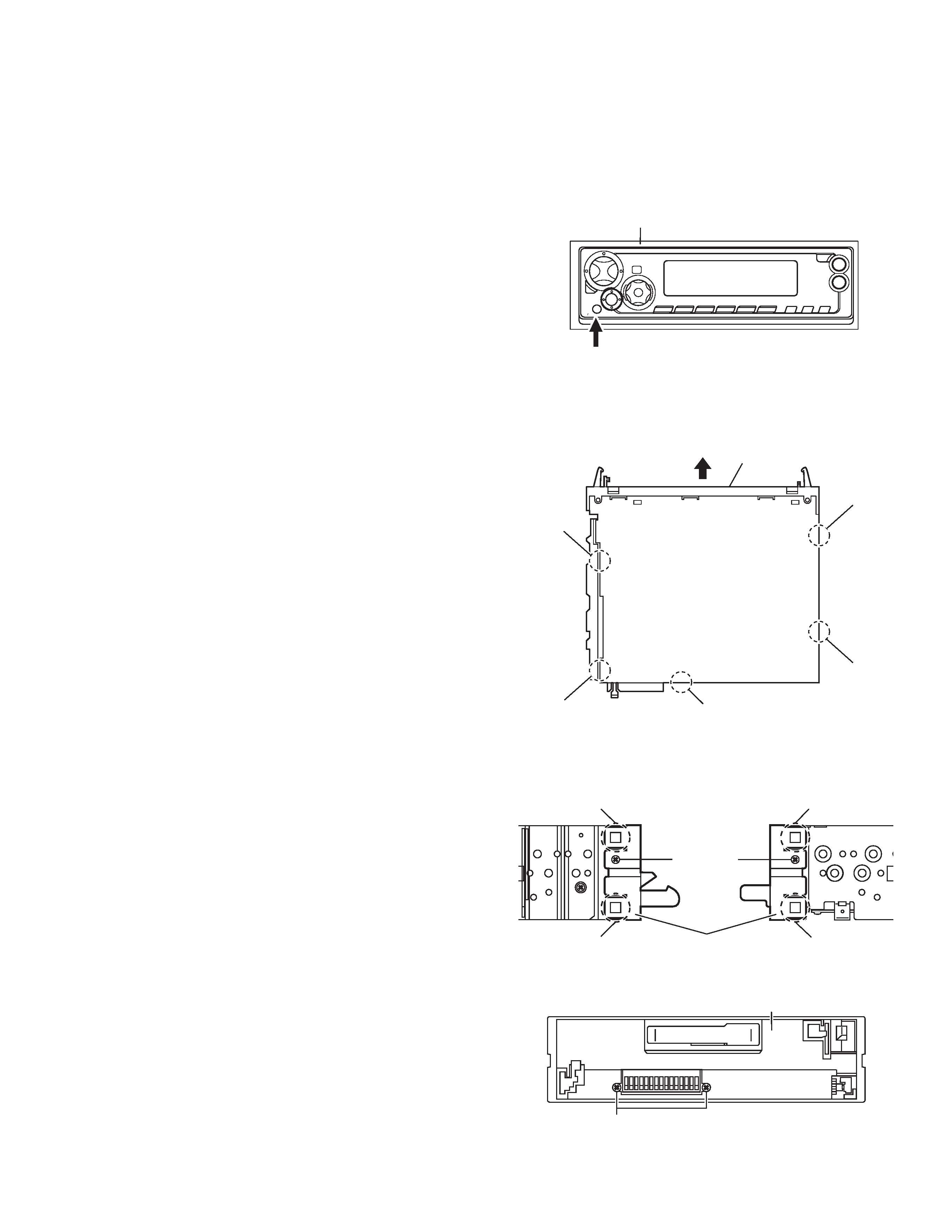
SECTION 3
DISASSEMBLY
3.1
Main body
3.1.1 Removing the front panel assembly
(See Fig.1)
(1) Press the release button and remove the front panel as-
sembly.
Fig.1
3.1.2 Removing the bottom cover
(See Fig.2)
· Prior to performing the following procedures, remove the front
panel assembly.
(1) Turn the main body upside down.
(2) Insert a screwdriver under the joints to release the two
joints a on the left side, two joints b on the right side and
joint c on the back side of the main body, then remove the
bottom cover from the main body.
CAUTION:
When releasing the joints using a screwdriver, do not damage
the main board.
Fig.2
3.1.3 Removing the front chassis assembly
(See Figs.3 and 4)
· Prior to performing the following procedures, remove the front
panel assembly and bottom cover.
(1) Remove the two screws A on the both sides of the main
body. (See Fig.3.)
(2) Remove the two screws B on the front side of the main
body. (See Fig.4.)
(3) Release the two joints d and two joints e on the both sides
of the main body, then remove the front chassis assembly
toward the front. (See Fig.3.)
Fig.3
Fig.4
Release button
Front panel assembly
Front chassis assembly
Joint b
Joint b
Joint a
Joint a
Joint c
Joint d
Joint d
Front chassis assembly
A
Joint e
Joint e
A
B
Front chassis assembly