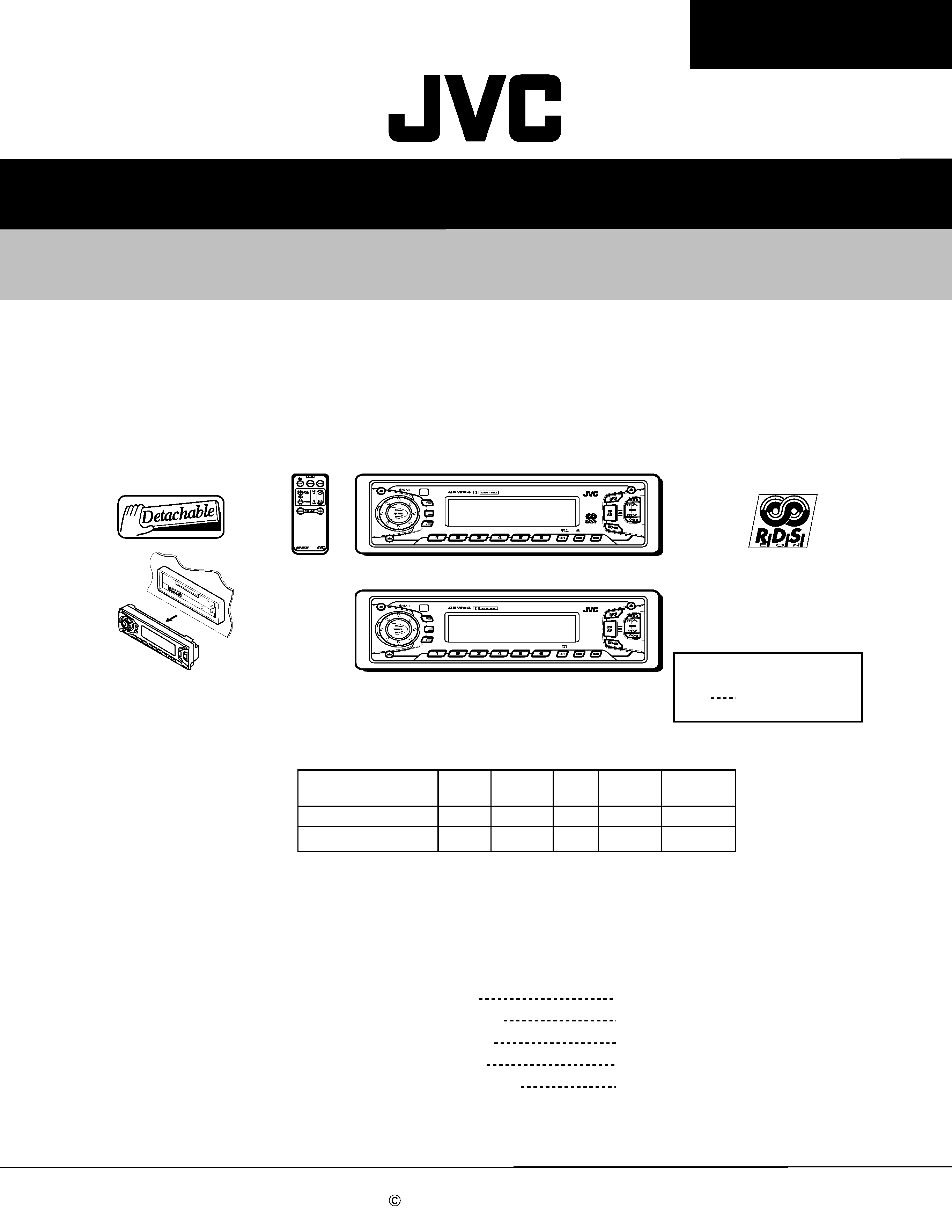
SERVICE MANUAL
CASSETTE RECEIVER
No.49613
Feb. 2001
COPYRIGHT
2001 VICTOR COMPANY OF JAPAN, LTD.
KS-FX915R/KS-FX815
KS-FX915R/KS-FX815
MO
TP
TP
RDS
RDS
PTY
PTY
DISP
DISP
8
9
10
11
12
7
DAB
MO
DISP
DISP
SCAN
SCAN
LOUD
LOUD
8
9
10
11
12
7
KS-FX915R
KS-FX815
KS-FX815
KS-FX915R
Area Suffix
EE
Russian Federation
Contents
Safety precaution
1- 2
Location of main parts
1- 3
Disassembly method
1- 4
Adjustment method
Description of major ICs
1-14
1-11
Difference point
KS-FX915R
KS-FX815
Dimmer Beep
RDS
LCD
Remocon
O
X
Color
Nega
O
X
O
X
O
X

KS-FX915R/KS-FX815
1-2
!
Burrs formed during molding may be left over on some parts of the chassis. Therefore,
pay attention to such burrs in the case of preforming repair of this system.
Safety precaution
KS-FX915R/KS-FX815
1-3
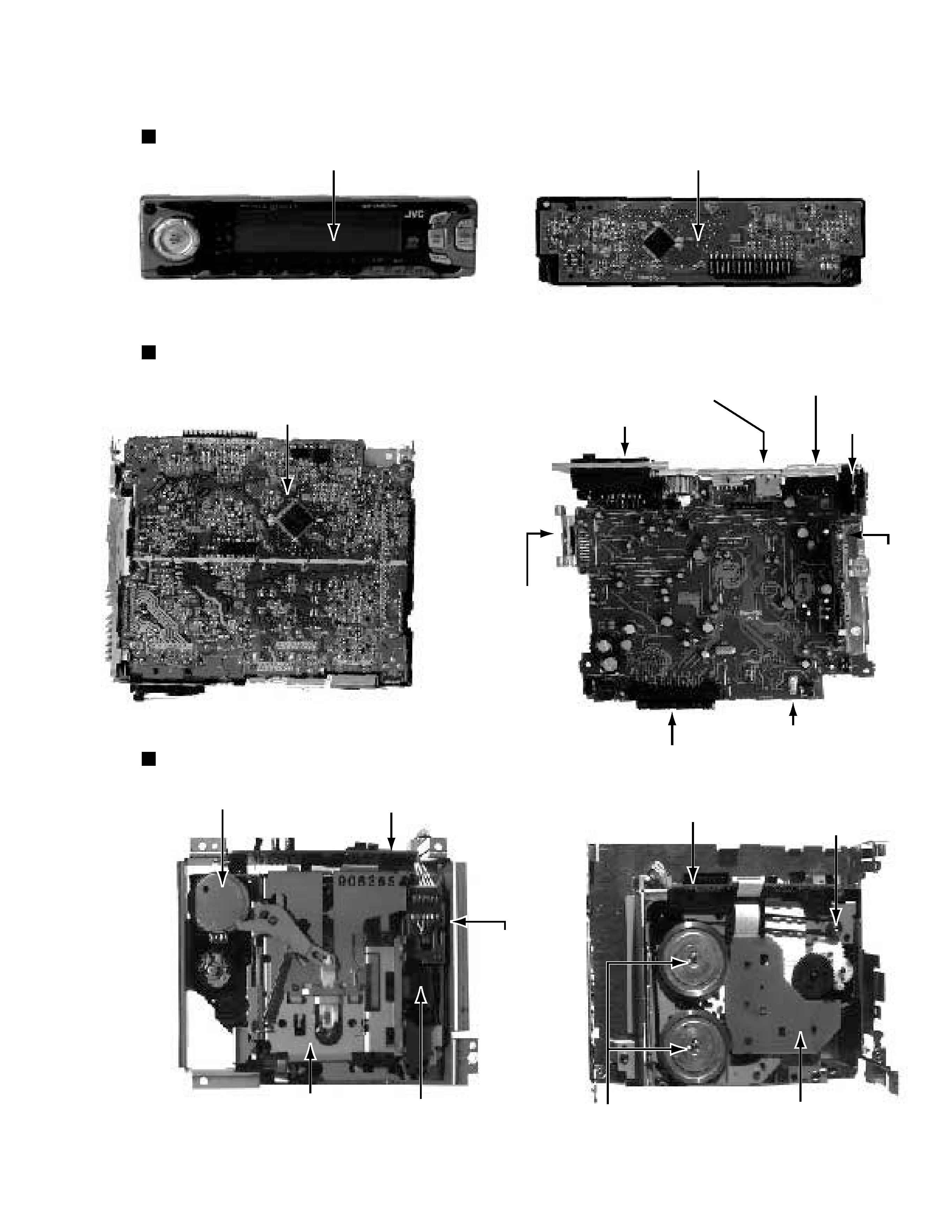
Location of main parts
Control unit
Display
Control unit
Main unit
Main board
Main board assembly
Power IC
Connector to controller
Tuner
pack
Antenna
jack
RCA jack
Changer control
connector
I/O connector
Cassette mechanism
Main board assembly
Connector to controller
Cassette mechanism
C.motor assembly
Mechanism control board assembly
Cassette housing
Head
Head relay board
Mechanism control board assembly
Flywheel assembly
Reel board
Capstan motor assembly
KS-FX915R/KS-FX815
1-4
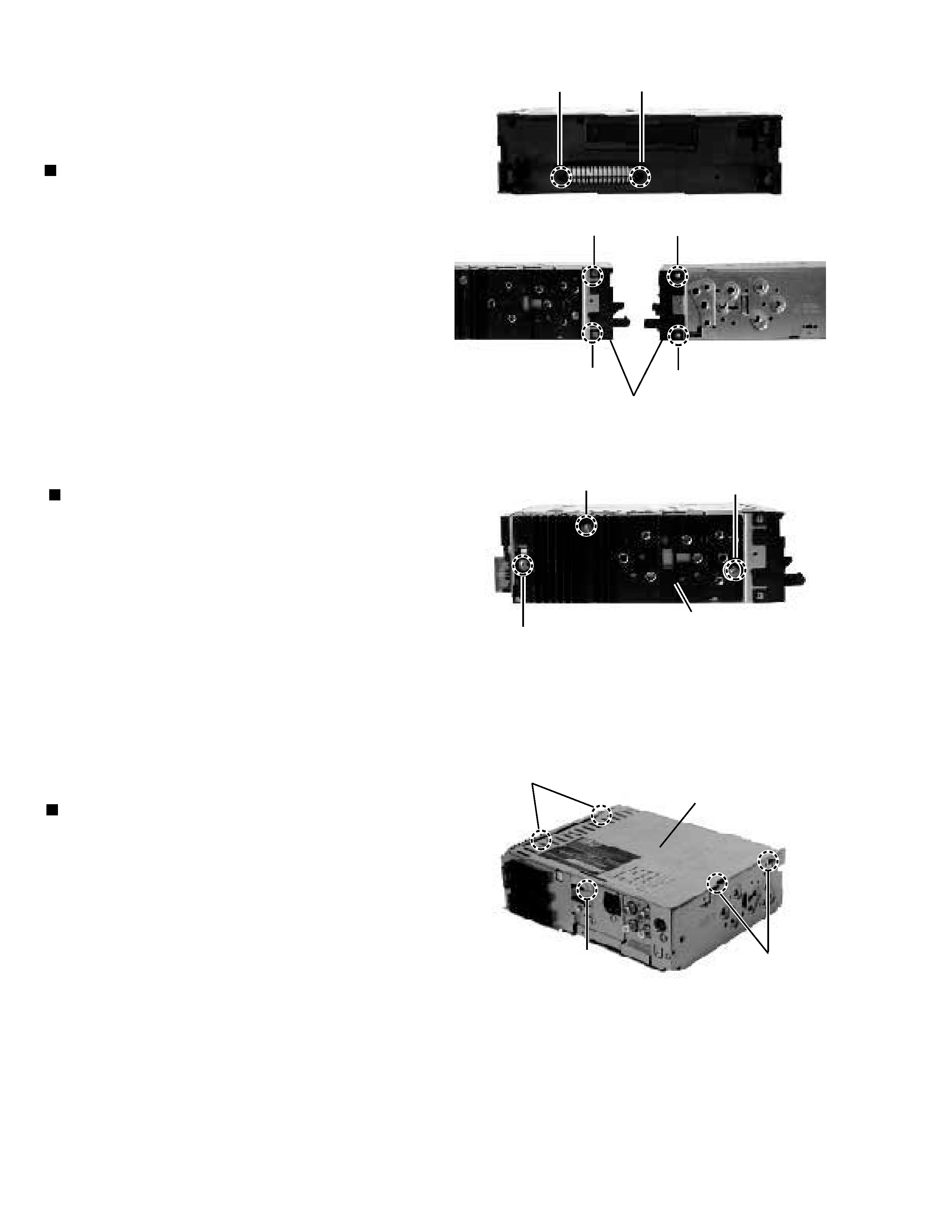
Disassembly method
Removing the front chassis (See Fig.1)
1. Remove two screws A and insert a screwdriver to the
joints a on the side of the front chassis and two joints b
on the right side, then detach the front chassis toward the
front side.
Removing the heat sink (See Fig.2 )
1. Remove the three screws B attaching the heat sink on
the left side of the body, and remove the heat sink.
Removing the bottom cover (See Fig.3 )
1.
2.
Turn the body upside down.
Insert a screwdriver to the two joints c and two joints d on
both sides of the body and the joint e on the back of the
body, then detach the bottom cover from the body.
Fig.1
Fig.2
Front chassis
b
a
a
b
Heat sink
B
B
B
Fig. 3
Regulator board
e
d
c
A
A
KS-FX915R/KS-FX815
1-5
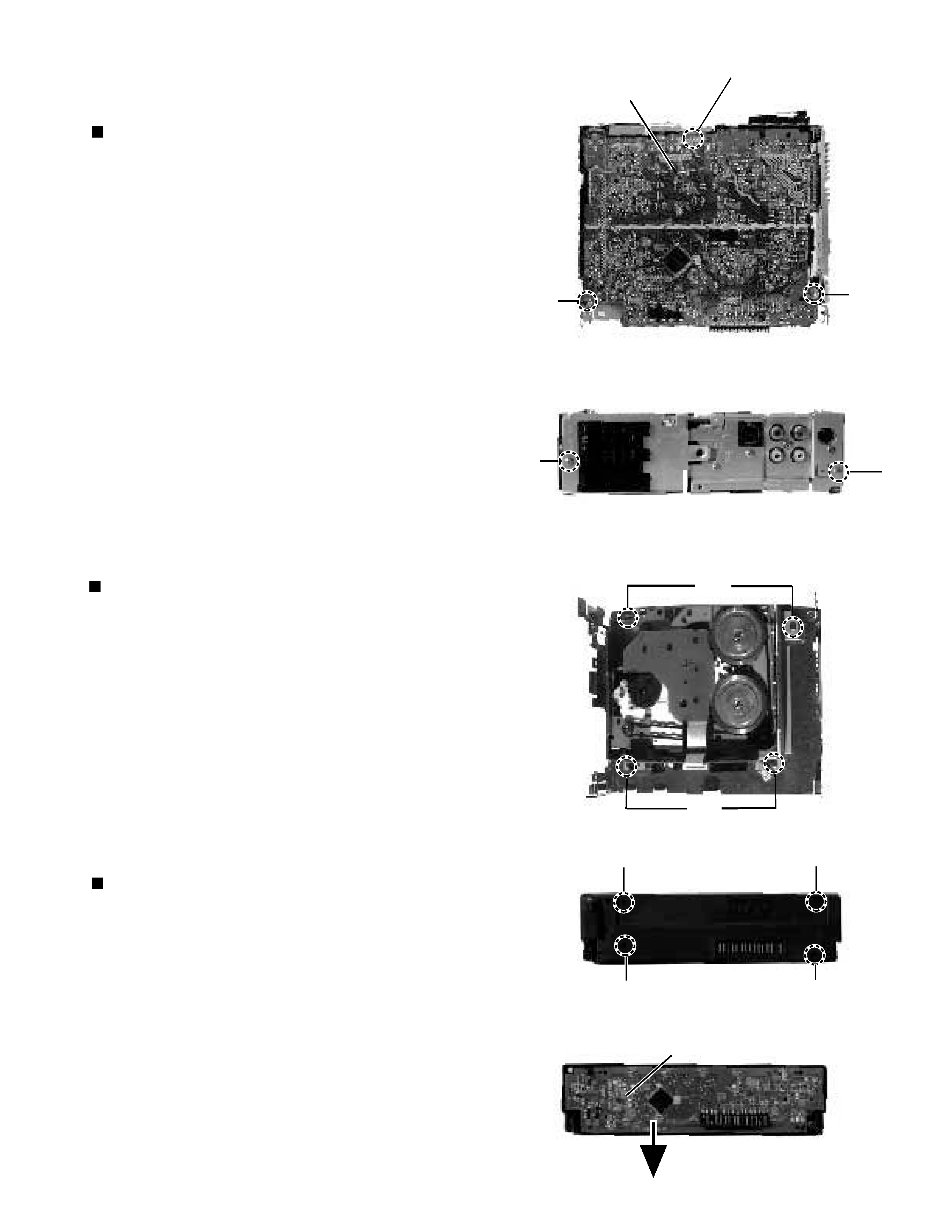
Removing the main amplifier board assembly
(See Fig.4 and 5)
1.
2.
3.
4.
5.
Remove the front chassis.
Remove the bottom cover.
Remove the two screws C attaching the main amplifier
board assembly on the bottom of the body.
Remove the three screws D attaching the main amplifier
board assembly on the back of the body.
Disconnect connector CP401 on the main amplifier board
assembly from the cassette mechanism assembly.
Removing the Cassette mechanism assembly
(See Fig.6 )
1.
2.
3.
4.
Remove the front chassis.
Remove the bottom cover.
Remove the main amplifier board assembly.
Remove the four screws E attaching the Cassette
mechanism assembly from the top cover.
Removing the control switch board
(See Fig.7 and 8 )
1.
2.
3.
Remove the front chassis.
Remove the four screws F attaching the rear cover on the
back of the front panel unit.
Remove the control switch board from the front panel
unit.
Fig. 5
D
D
F
F
F
F
Fig. 7
Fig. 8
Control switch board
E
Fig. 6
E
Fig.4
C
C
Main amplifier board
CP401