SERVICE MANUAL
CASSETTE RECEIVER
No.49730
Apr. 2002
COPYRIGHT
2002 VICTOR COMPANY OF JAPAN, LTD.
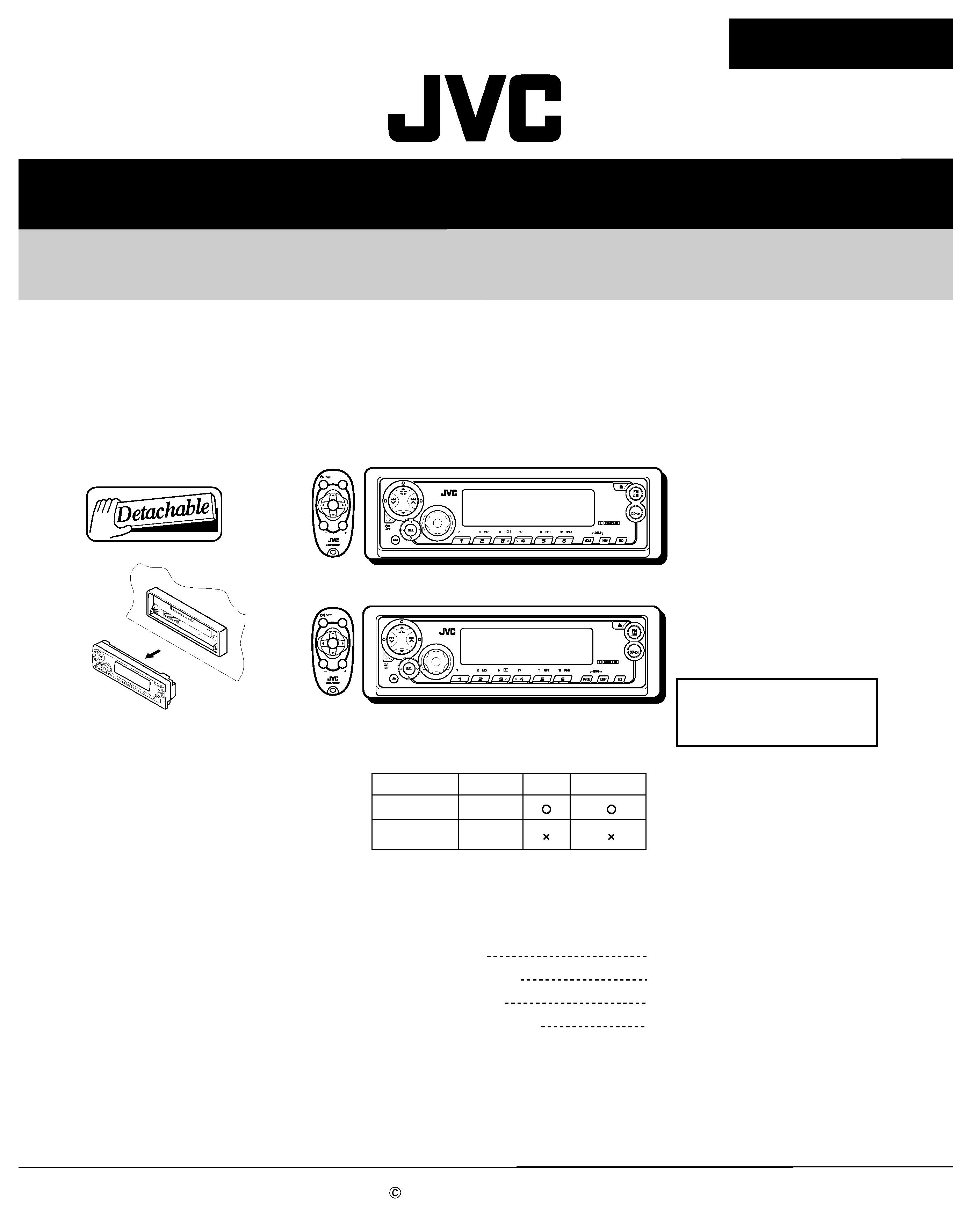
KS-FX911/KS-FX811
KS-FX911/KS-FX811
Contents
Safety precaution
Disassembly method
Adjustment method
Description of major ICs
1- 2
1- 3
1-17
1-20~29
50W X 4
KS-FX911
Multi
Music
Scan
TAPE
SOUND
VOL
VOL
SOURCE
R
F
U
D
50W X 4
KS-FX811
Multi
Music
Scan
TAPE
SOUND
VOL
VOL
SOURCE
R
F
U
D
KS-FX911
KS-FX811
Difference point
KS-FX911
KS-FX811
LCD Display
Multi
Nega
Dimmer Cellular Muting
Area Suffix
U --------------------- Other Areas
KS-FX911/KS-FX811
1-2
!
Burrs formed during molding may be left over on some parts of the chassis. Therefore,
pay attention to such burrs in the case of preforming repair of this system.
Safety precaution
KS-FX911/KS-FX811
1-3
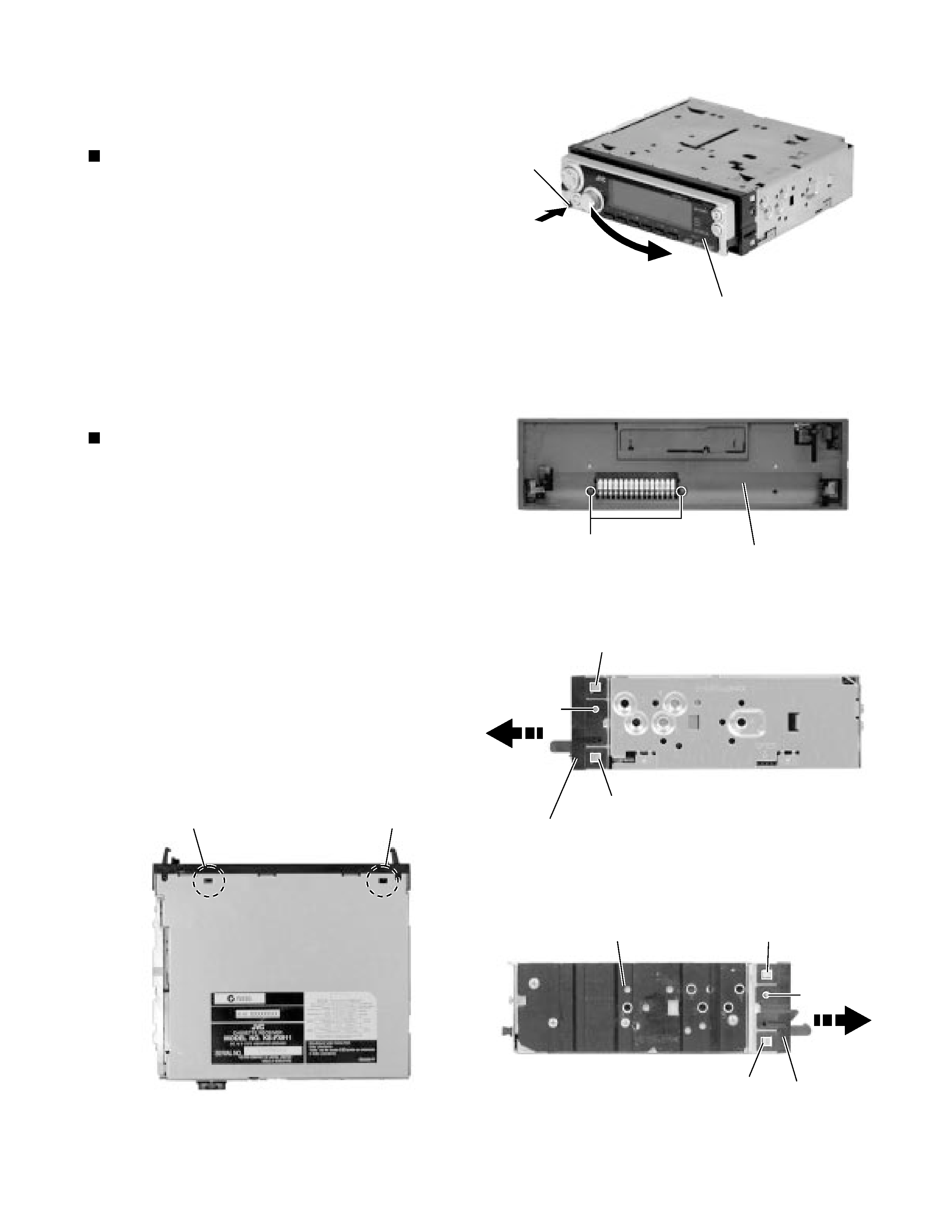
Press the release switch and remove the front panel
unit in the direction of the arrow.
1.
Removing the front panel unit
(See Fig.1)
Remove the two screws A attaching the front
chassis.
Remove the two screws B on each side of the body.
Release the two joints a and the two joints b on the
sides. Release the two joints c at the bottom and
remove the front chassis toward the front.
1.
2.
3.
Removing the front chassis
(See Fig.2 to 4)
Disassembly method
<Main body>
Fig.1
Fig.2
Fig.3-1
Fig.3-2
Fig.4
Front panel assembly
Eject button
Joint a
Joint a
Front chassis assembly
Front chassis
assembly
Heat sink
Joint b
Joint b
Front chassis assembly
A
B
Joint c
Joint c
B
KS-FX911/KS-FX811
1-4
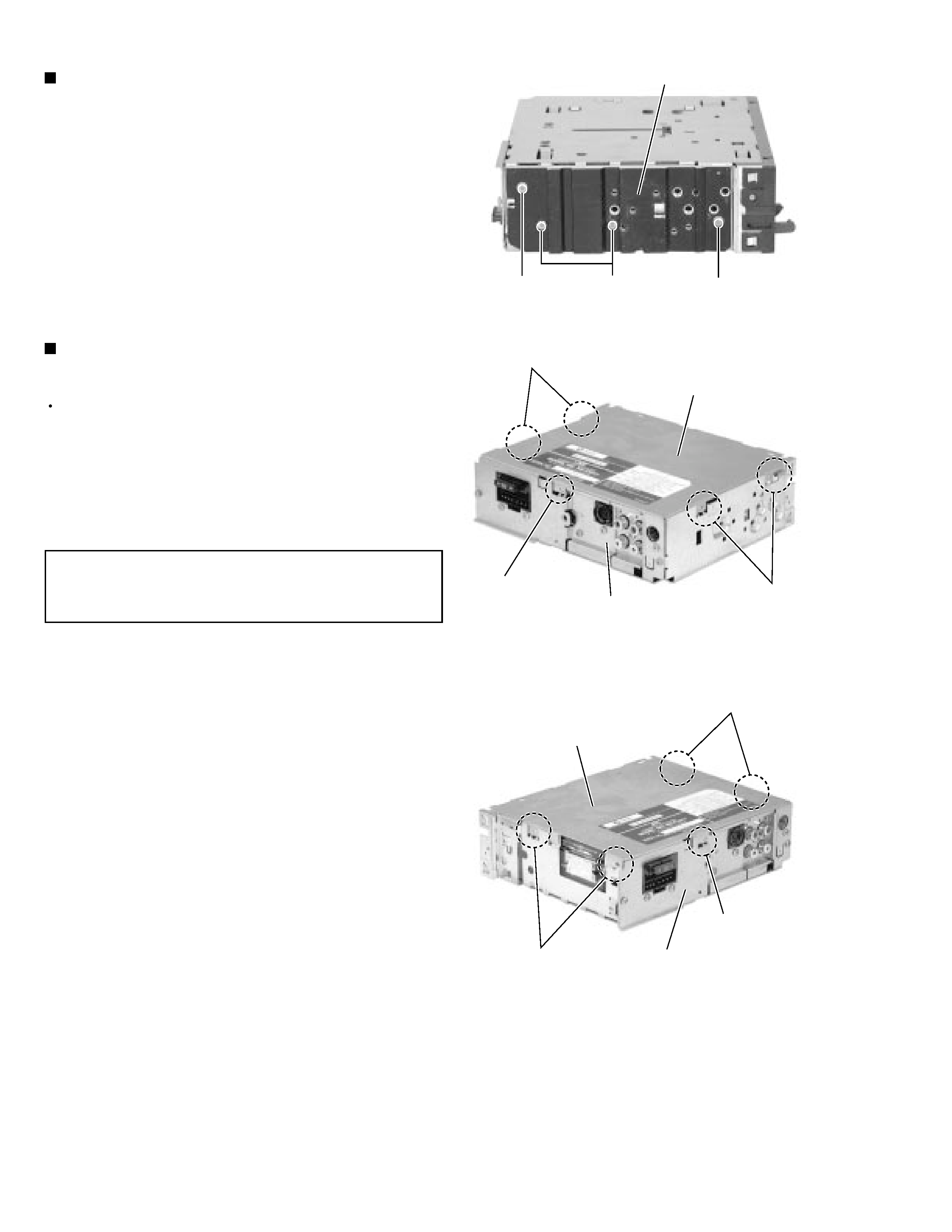
Remove the two screws C and the two screws D on
the left side of the body.
1.
Removing the heat sink (See Fig.5)
Prior to performing the following procedure, remove
the front panel assembly, the front chassis assembly
and the heat sink.
Turn over the body and unjoint the four joints c and
joint d with the bottom cover and the body using a
screwdriver.
1.
Removing the bottom cover
(See Fig.6 and 7)
When disengaging the joint d using a
screwdriver, do not damage or break the
main board.
CAUTION:
Fig.5
Fig.6
Fig.7
Heat sink
C
D
Joint c
Joint c
Joint d
Joint c
Joint c
Joint d
Bottom cover
Bottom cover
Rear panel
Rear panel
D
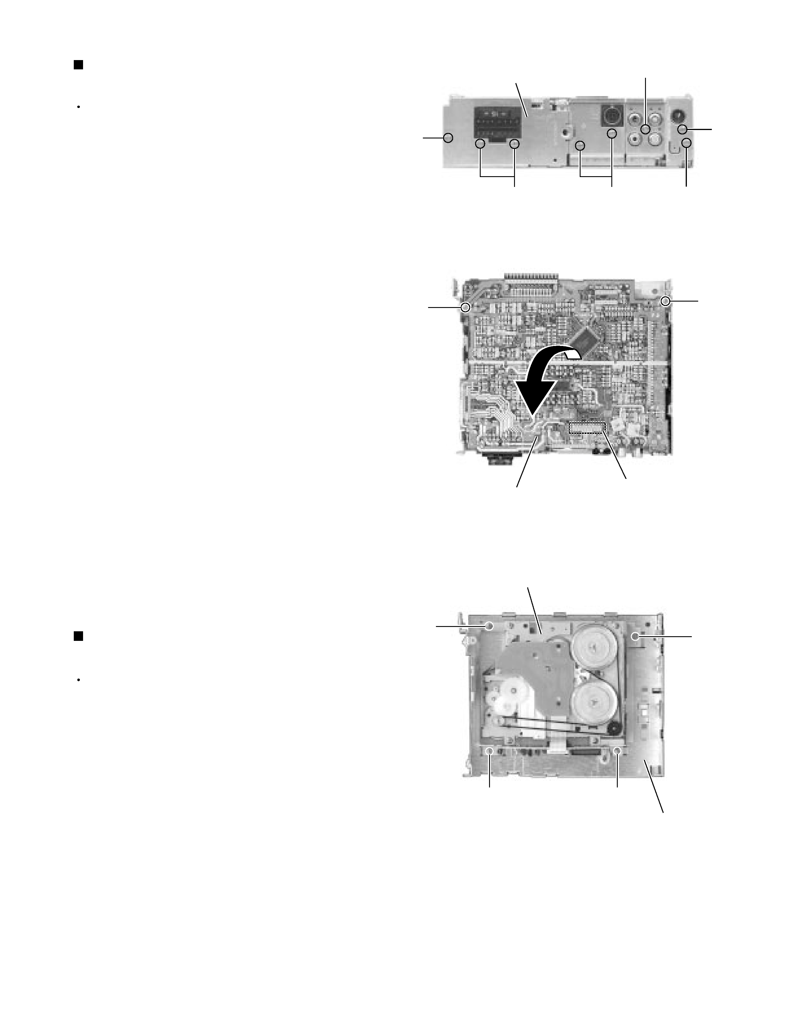
KS-FX911/KS-FX811
1-5
Prior to performing the following procedure, remove
the front panel assembly, the front chassis assembly,
the heat sink and the bottom cover.
Remove the screw E, the five screws F and the two
screws G attaching the rear panel on the back of the
body. Remove the rear panel.
Remove the two screws H attaching the main board
on the bottom of the body. Disconnect connector
CN701 on the main board in the direction of the
arrow.
1.
2.
Removing the main board
(See Fig.8 and 9)
Prior to performing the following procedure, remove
the front chassis, the heat sink, bottom cover and the
main amplifier board assembly.
Remove the four screws I
attaching the cassette
mechanism assembly from the top cover.
1.
Removing the cassette mechanism assembly
(See Fig.10)
Fig.8
Fig.9
Fig.10
Main board assembly
H
H
Cassette mechanism assembly
I
I
Top cover
I
I
G
F
FG
F
E
Rear panel
CN701