SERVICE MANUAL
CASSETTE RECEIVER
No.49580
Jan. 2001
COPYRIGHT
2001 VICTOR COMPANY OF JAPAN, LTD.
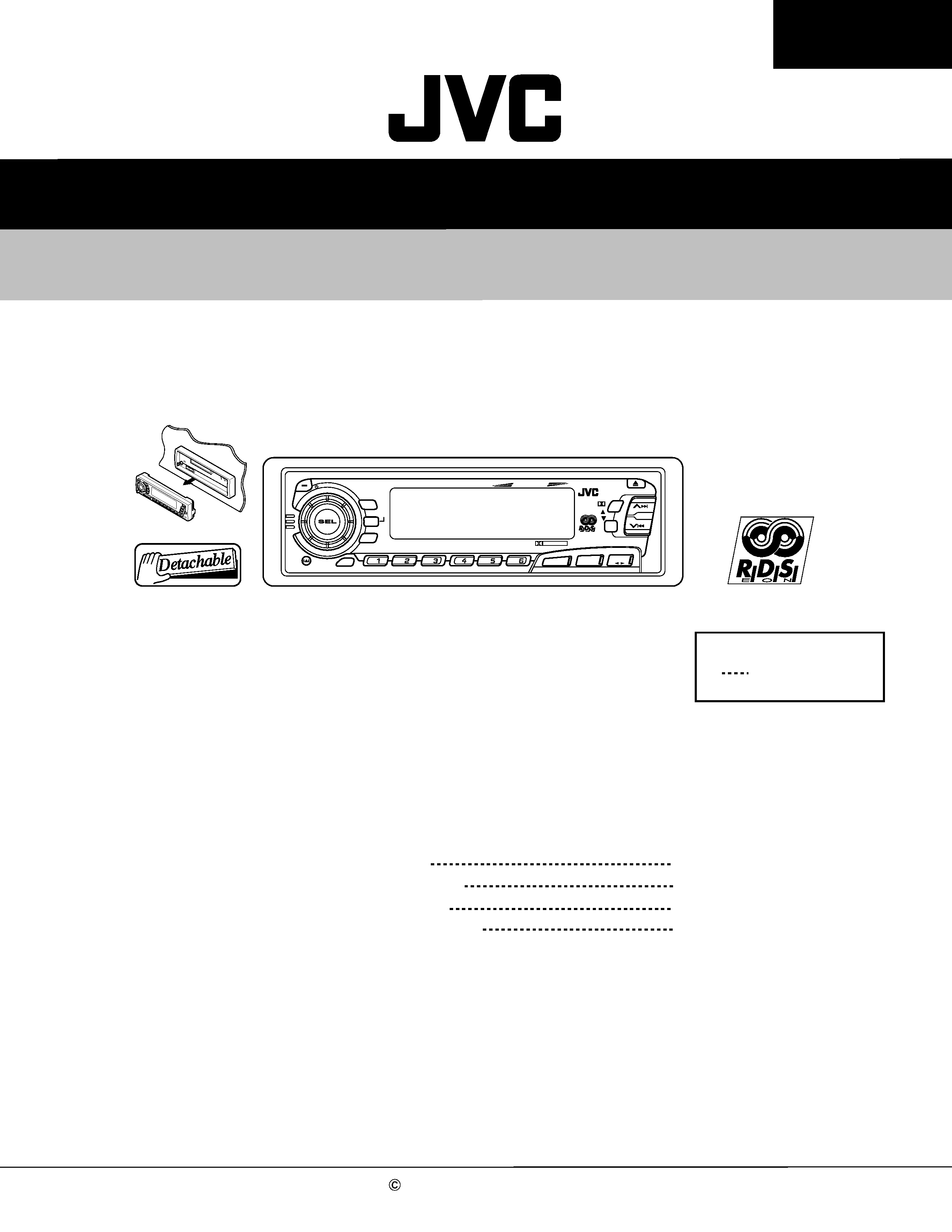
KS-FX8R
KS-FX8R
Area Suffix
E
Continental Europe
40Wx4
TP
DISP
RPT
SSM
SCM
MO
RND
789
10
11
12
PTY
CD-CH
FM/AM
TAPE
/I ATT
/
DOLBY B NR
DAB
RDS
KS-FX8R
KS-FX8R
Contents
Safety precaution
Disassembly method
Adjustment method
Description of major ICs
1-2
1-3
1-10
1-14
KS-FX8R
1-2
!
Burrs formed during molding may be left over on some parts of the chassis. Therefore,
pay attention to such burrs in the case of preforming repair of this system.
Safety precaution
KS-FX8R
1-3
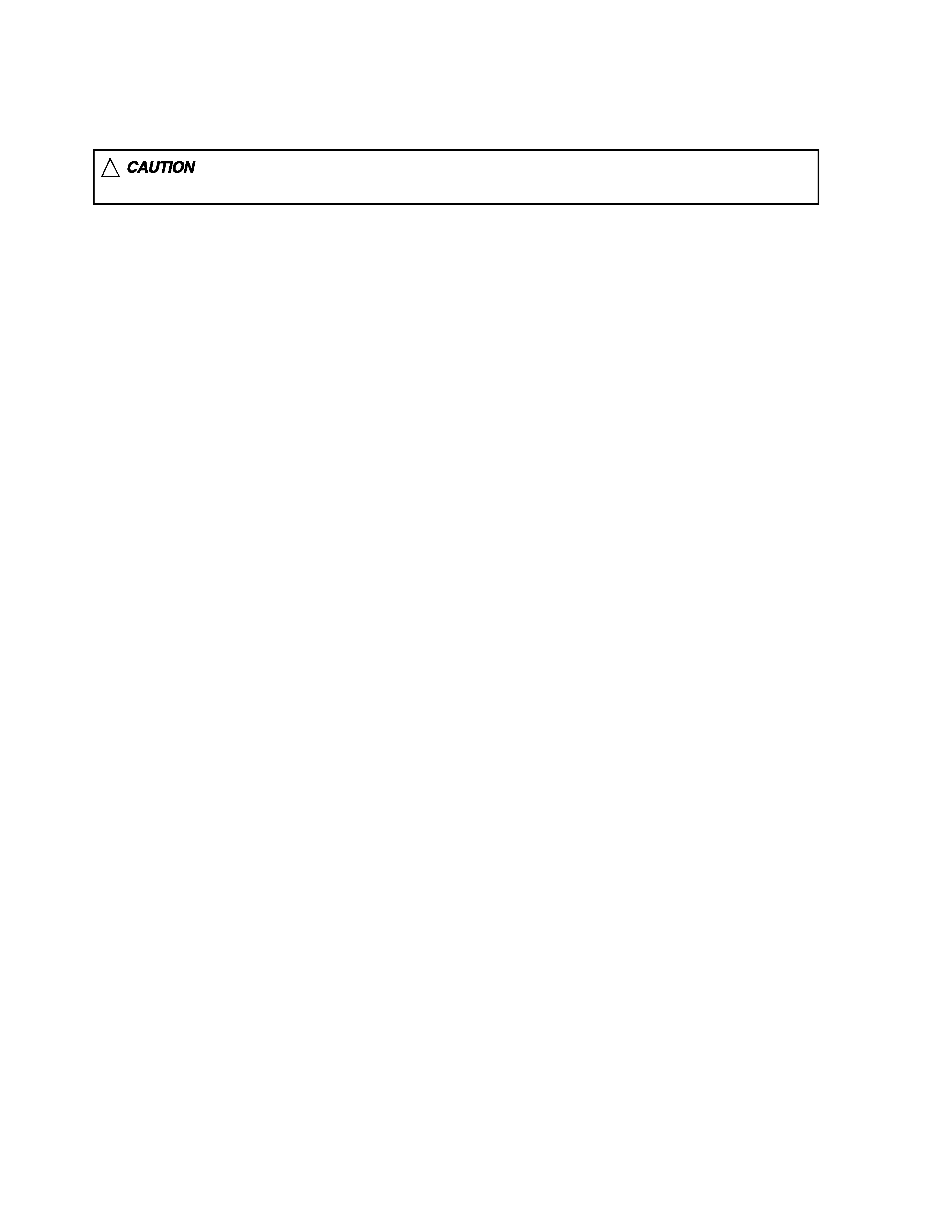
Press the release switch and remove the front panel
unit in the direction of the arrow.
1.
Disassembly method
Removing the front panel unit
(See Fig.1)
Remove the two screws A attaching the front chassis.
Insert a screwdriver to the two joints a on the left
side of the front chassis, two joints b on the right side
and one joint c from upside, then detach the front
chassis toward the front side.
1.
2.
Removing the front chassis (See Fig.2~3)
Remove the three screws B attaching the heat sink
on the left side of the body, and remove the heat
sink.
1.
Removing the heat sink (See Fig.4)
Joint c
Heat sink
Fig.2
Fig.1
Fig. 3
Fig. 4
Front panel unit
Front chassis
A
Front chassis
Joint a
Joint a
Joint b
Joint b
B
B
KS-FX8R
1-4
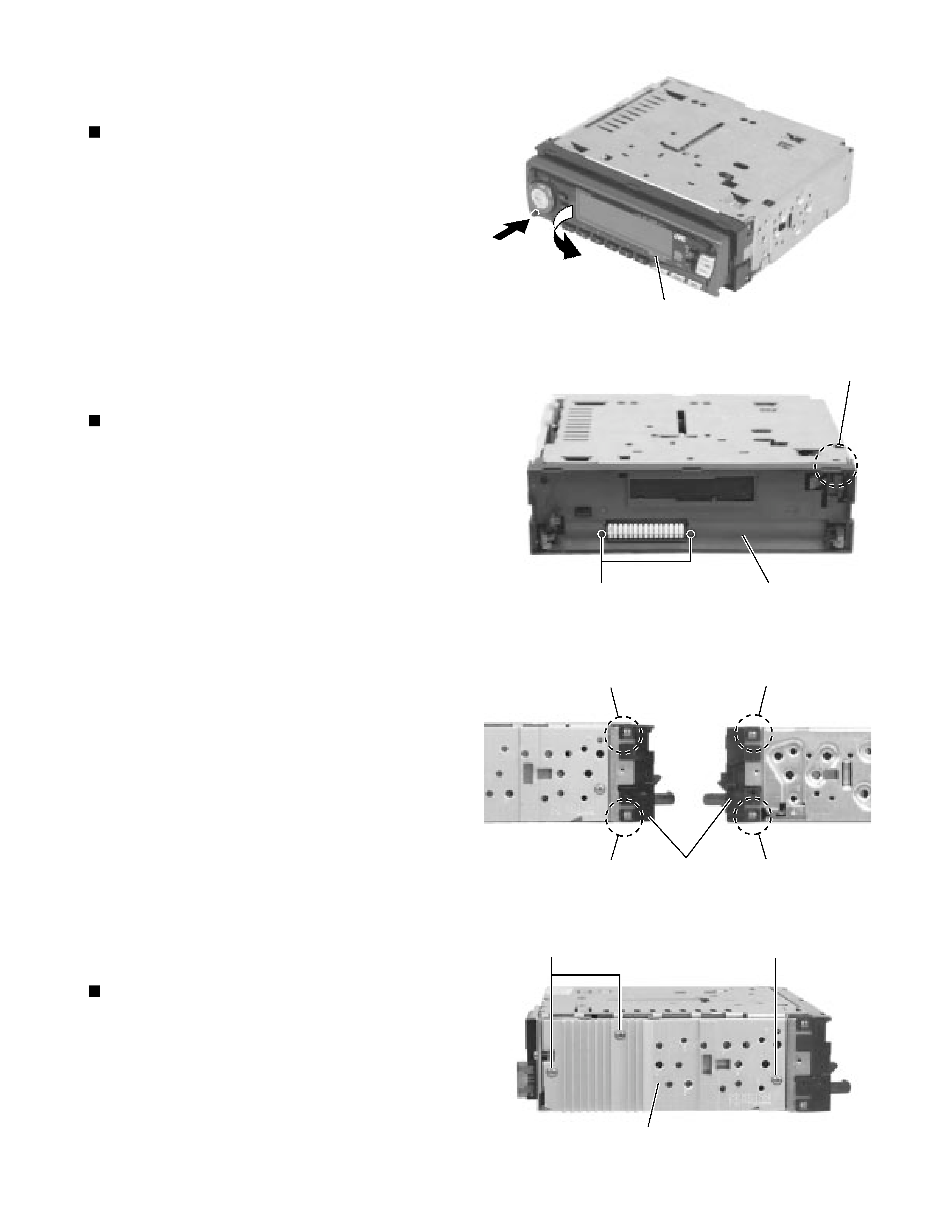
Prior to performing the following procedure, remove
the front chassis and the heat sink.
Turn the body upside down.
Insert a screwdriver to the two joints d and two joints
e on both sides of the body and the joint f on the
back of the body, then detach the bottom cover from
the body.
1.
2.
Removing the bottom cover (See Fig.5)
Prior to performing the following procedure, remove
the front chassis, the heat sink and bottom cover.
Remove the five screws C attaching the rear panel
and one screw D attaching the pine jack on the back
of the body.
1.
Removing the rear panel (See Fig.6 )
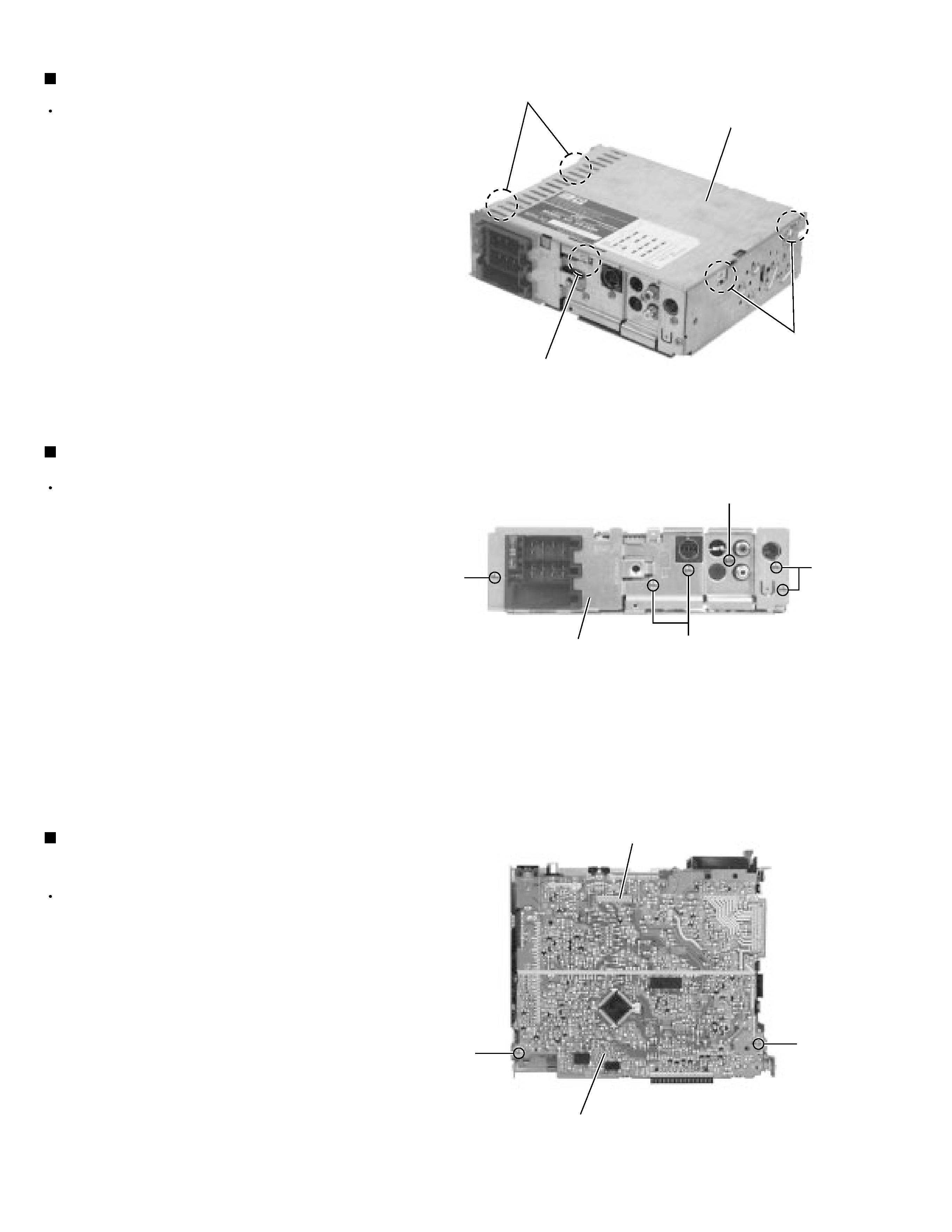
Prior to performing the following procedure, remove
the front chassis, the heat sink, bottom cover and the
rear panel.
Remove the two screws E
attaching the main
amplifier board assembly on the top cover.
Disconnect connector CP401 on the main amplifier
board assembly from the cassette mechanism
assembly.
1.
2.
Removing the main amplifier board assembly
(See Fig.7)
Bottom cover
Fig. 5
Fig. 6
Fig. 7
Main board assembly
Joints d
Joints e
Joint f
C
C
C
D
Rear panel
CP401
E
E
KS-FX8R
1-5
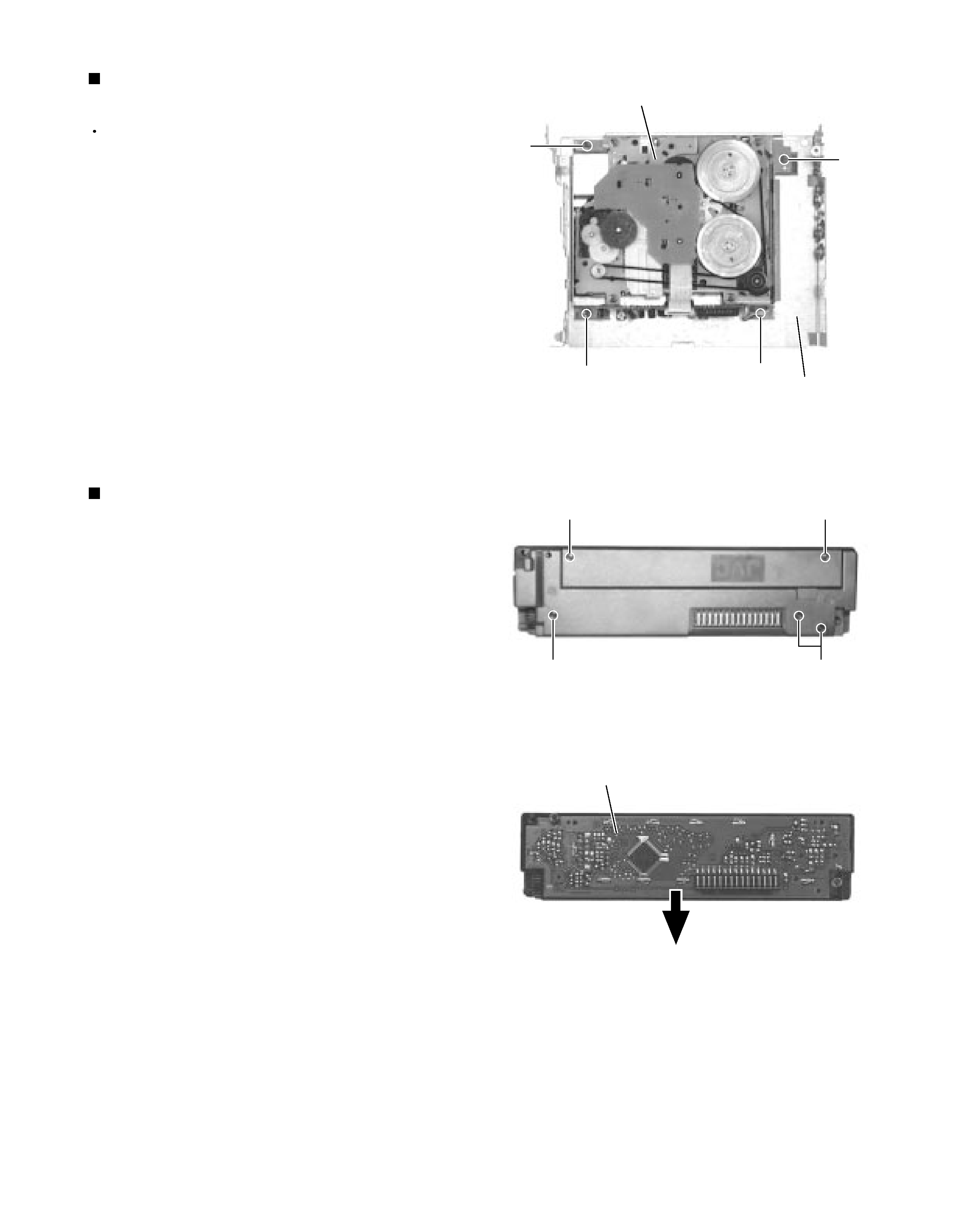
Prior to performing the following procedure, remove
the front chassis, the heat sink, bottom cover and the
main amplifier board assembly.
Remove the four screws F
attaching the cassette
mechanism assembly from the top cover.
1.
Removing the cassette mechanism assembly
(See Fig.8)
Remove the front panel unit from the main body.
Remove the five screws G attaching the rear cover
on the back of the front panel unit.
Remove the control switch board from the front panel
unit.
1.
2.
3.
Removing the (LCD & key) control switch
board (See Fig.9 and 10 )
Cassette mechanism assembly
F
F
F
Top cover
Fig. 8
G
G
G
G
Fig. 9
Fig. 10
LCD & Key control board
F