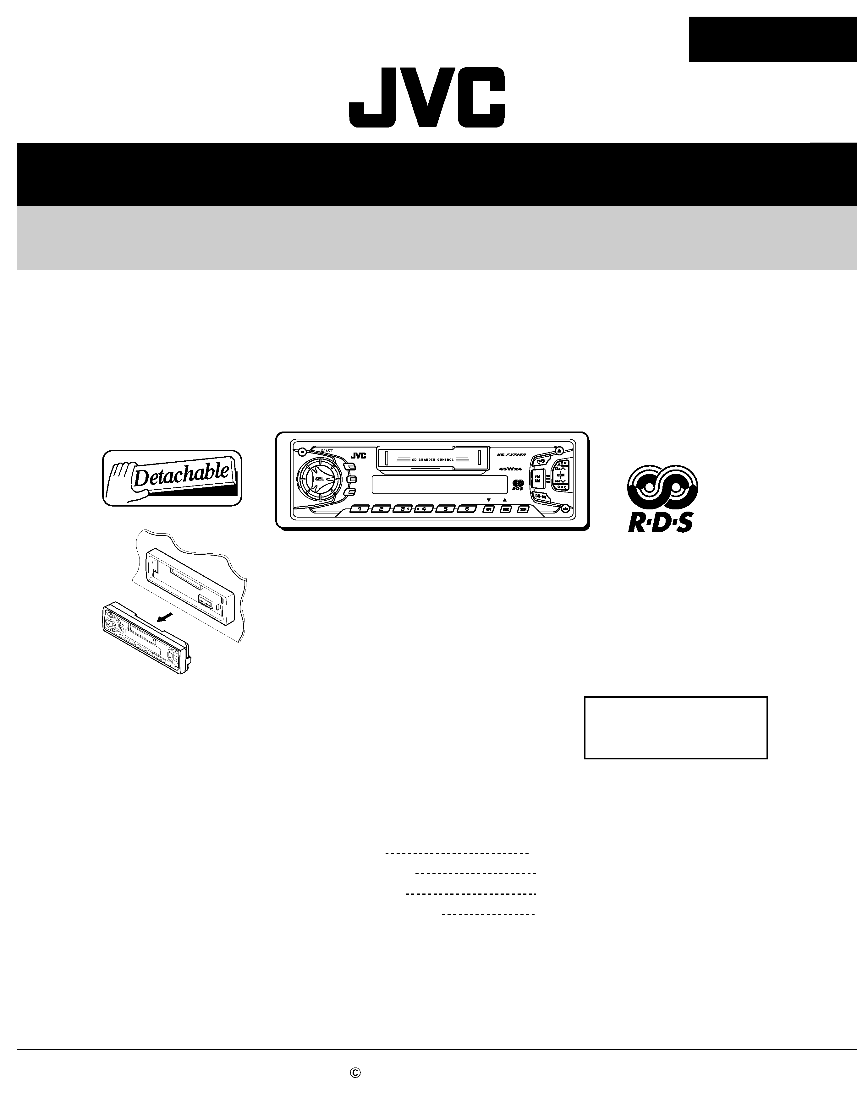
SERVICE MANUAL
CASSETTE RECEIVER
No.49721
Mar. 2002
COPYRIGHT
2002 VICTOR COMPANY OF JAPAN, LTD.
KS-FX725R
KS-FX725R
Area Suffix
EE ---- Russian Federation
Contents
Safety precaution
Disassembly method
Adjustment method
Description of major ICs
1-2
1-3
1-18
1-22
MO
TP
TP
RDS
RDS
PTY
PTY
DISP
DISP
8
9
10
11
12
7
DAB
1-2
KS-FX725R
!
Burrs formed during molding may be left over on some parts of the chassis. Therefore,
pay attention to such burrs in the case of preforming repair of this system.
Safety precaution
1-3
KS-FX725R
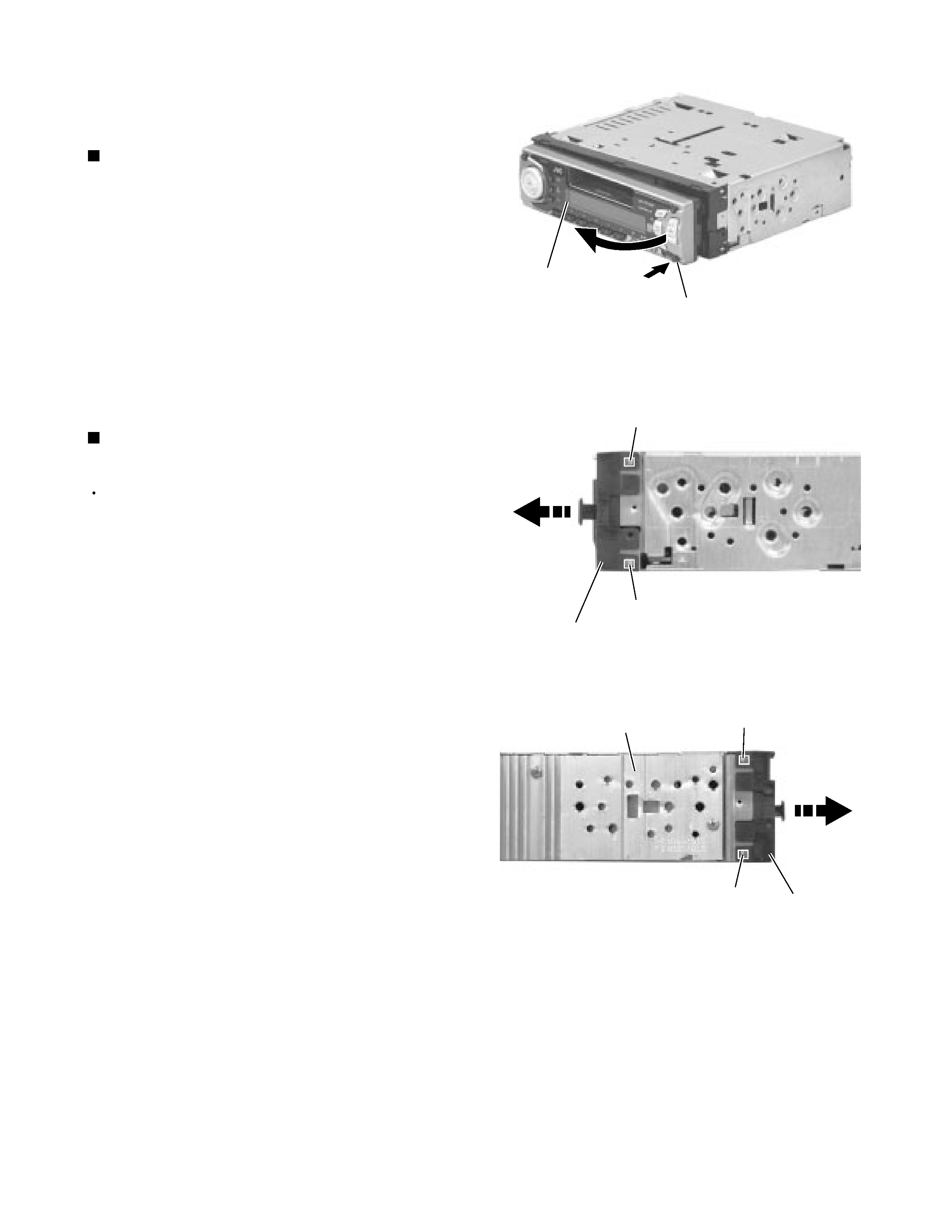
Press the eject button in the lower right part of the
front panel. Remove the front panel assembly from
the body.
1.
Removing the front panel assembly
(See Fig.1)
Prior to performing the following procedure, remove
the front panel assembly.
Release the four joints a on both sides of the front
chassis assembly and remove the front chassis
assembly toward the front.
1.
Removing the front chassis assembly
(See Fig.2 , 3)
Disassembly method
<Main body>
Fig.1
Fig.2
Fig.3
Front panel assembly
Eject button
Joint a
Joint a
Front chassis assembly
Front chassis
assembly
Heat sink
Joint a
Joint a
1-4
KS-FX725R
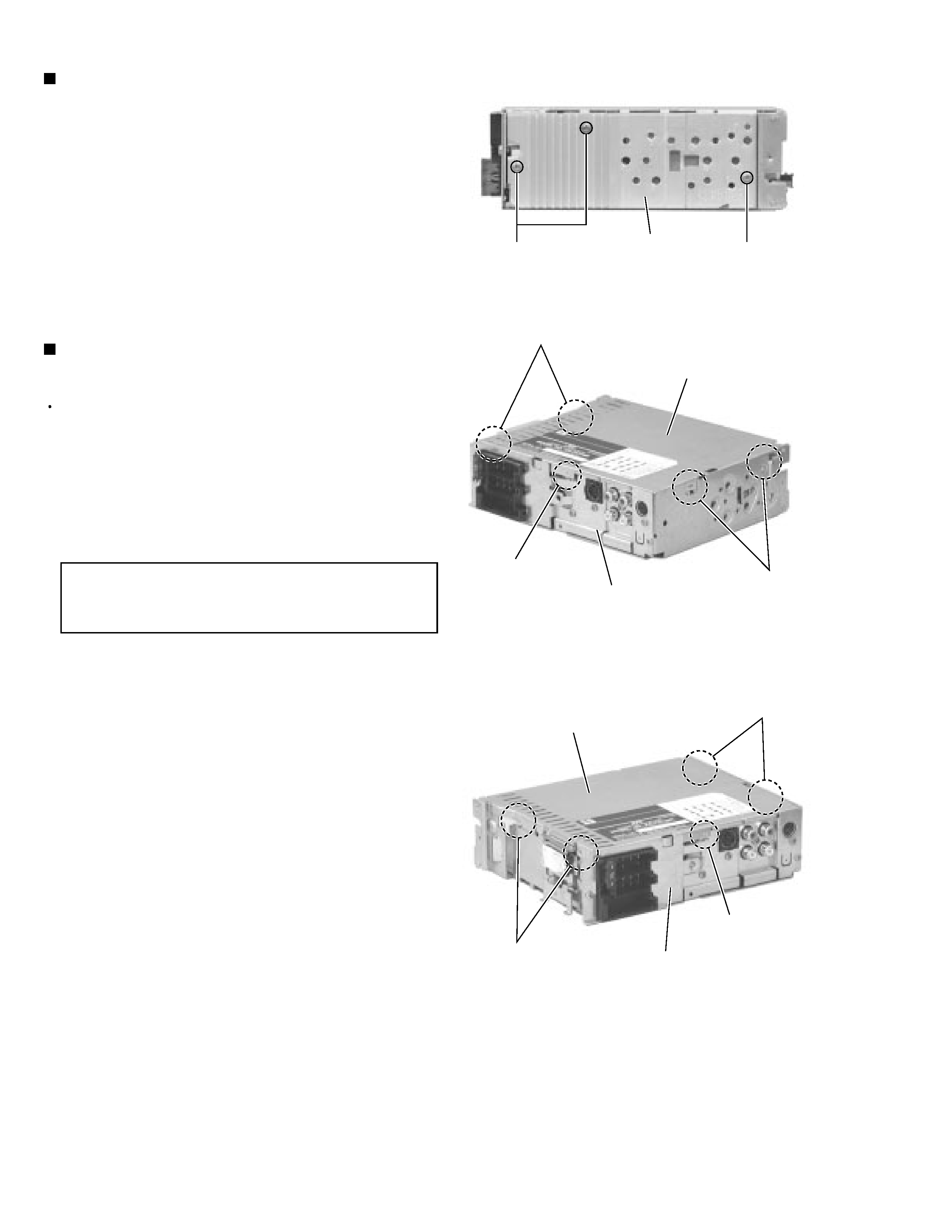
Remove the three screws A on the left side of the
body.
1.
Removing the heat sink (See Fig.4)
Prior to performing the following procedure, remove
the front panel assembly, the front chassis assembly
and the heat sink.
Turn over the body and unjoint the five joints b with
the bottom cover and the body using a screwdriver.
1.
Removing the bottom cover
(See Fig.5 , 6)
When disengaging the joint c using a
screwdriver, do not damage or break the
board.
CAUTION:
Fig.4
Fig.5
Fig.6
Heat sink
AA
Joint b
Joint b
Joint c
Joint b
Joint b
Joint c
Bottom cover
Bottom cover
Rear panel
Rear panel
1-5
KS-FX725R
Prior to performing the following procedure, remove
the front panel assembly, the front chassis assembly,
the heat sink and the bottom cover.
Remove the screw B, the three screws C and the
two screws D attaching the rear bracket on the back
of the body. Remove the rear panel.
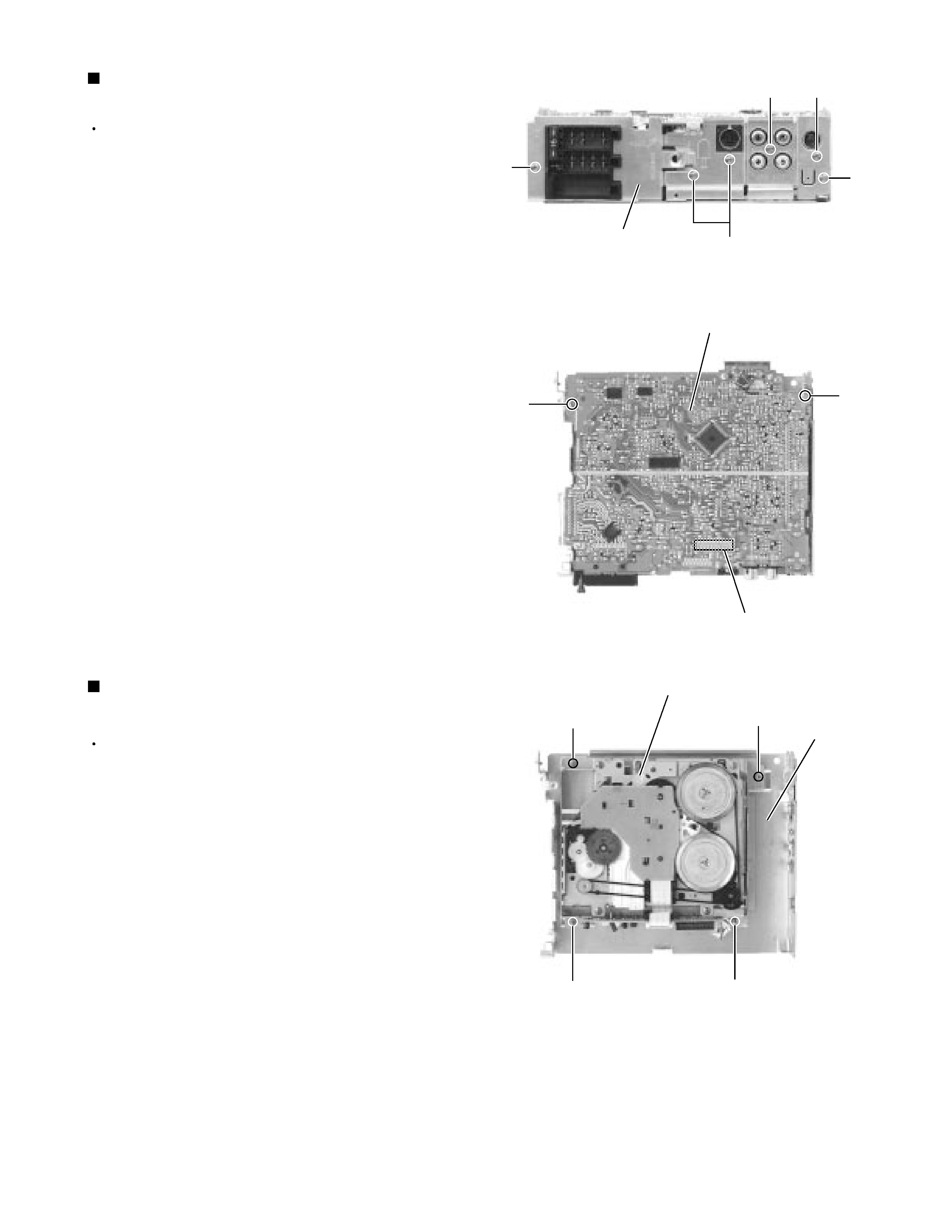
Remove the two screws E attaching the main board
on the bottom of the body. Disconnect connector
CP401 on the main board in the direction of the
arrow.
1.
2.
Removing the main board
(See Fig.7 , 8)
Prior to performing the following procedure, remove
the front panel assembly, the front chassis assembly,
the heat sink, the bottom cover and the main board.
Remove the four screws F
attaching the cassette
mechanism section on the back of the top chassis.
1.
Removing the cassette mechanism section
(See Fig.9)
Fig.7
Fig.8
Fig.9
Rear panel
B
D
D
C
C
Main board
E
E
CP401
Cassette mechanism section
F
F
F
F
Top chassis