SERVICE MANUAL
CASSETTE RECEIVER
No.49591
Jan. 2001
COPYRIGHT
2001 VICTOR COMPANY OF JAPAN, LTD.
KS-FX722R
KS-FX722R
Area Suffix
E ---- Continental Europe
Contents
Safety precaution
Location of main parts
Disassembly method
1-2
1-3
1-4
Adjustment method
Wiring connections
Description of major ICs
1-10
1-14
1-15
MO
TP
TP
RDS
RDS
PTY
PTY
DISP
DISP
8
9
10
11
12
7
DAB
KS-FX722R
1-2
!
Burrs formed during molding may be left over on some parts of the chassis. Therefore,
pay attention to such burrs in the case of preforming repair of this system.
Safety precaution
KS-FX722R
1-3
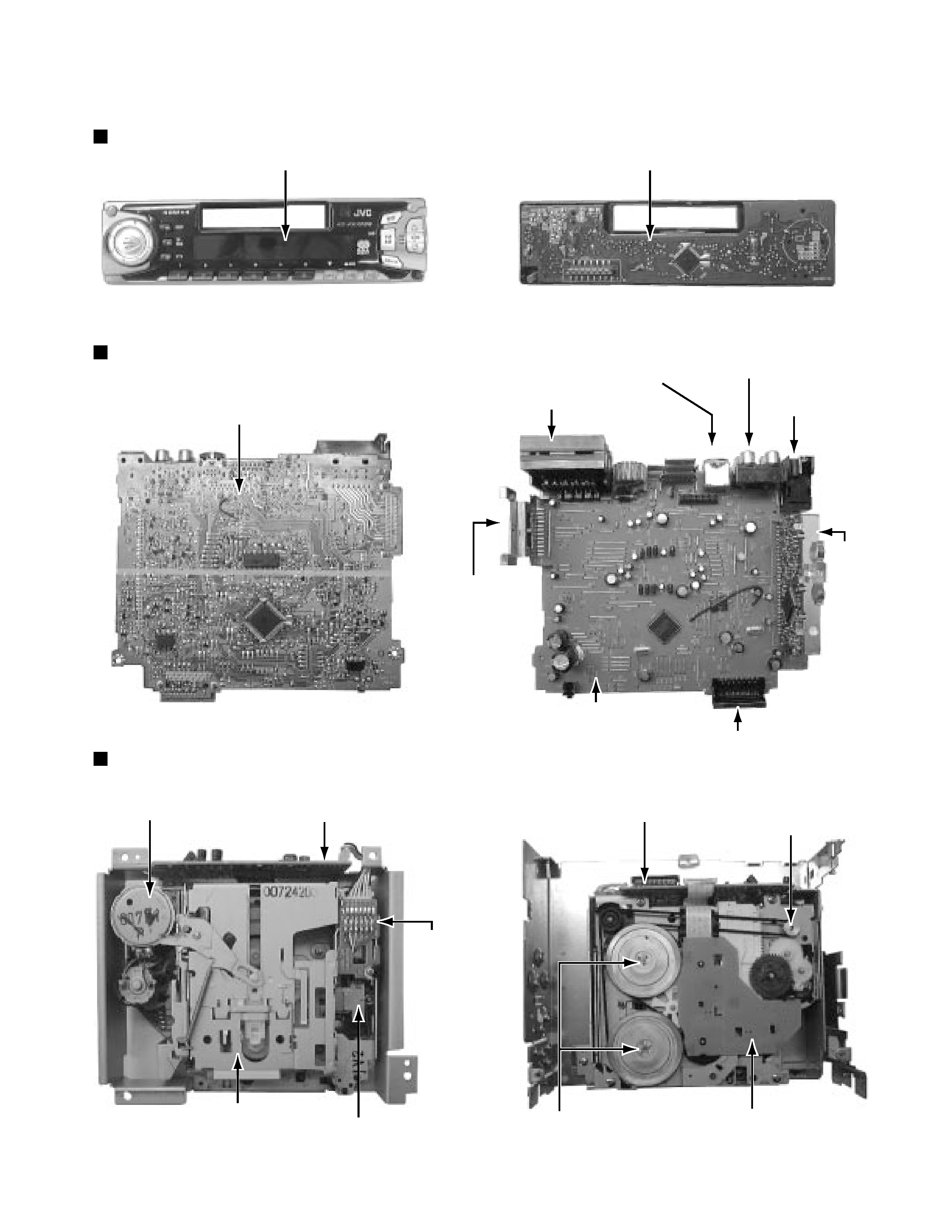
Location of main parts
Control unit
Display
Control unit
Main unit
Main board
Main board assembly
Power IC
Connector to controller
Tuner
pack
Antenna
jack
RCA jack
Changer control
connector
I/O connector
Cassette mechanism
C.motor assembly
Mechanism control board assembly
Cassette housing
Head
Head relay board
Mechanism control board assembly
Flywheel assembly
Reel board
Capstan motor assembly
KS-FX722R
1-4
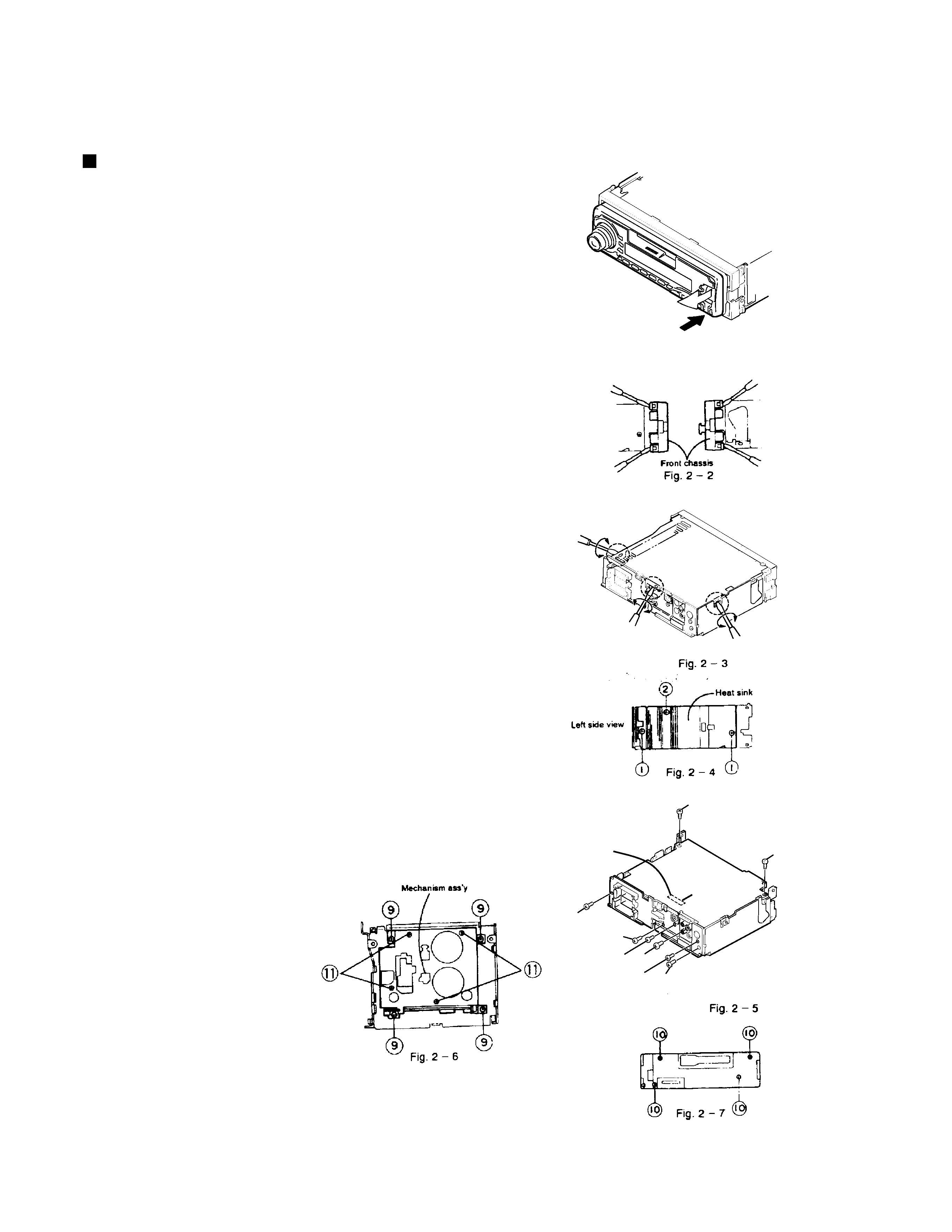
Disassembly method
Removal of main parts
(1) Detaching the front panel unit (see Fig.2-1)
Side the Release slide knob in the direction of arrow
to detach the front panel unit.
(2) Removing the front chassis(see Fig.2-2)
Disengage the four tabs in the right and left sides of unit
and pull the front chassis forward to remove it.
(3) Removing the bottom cover(see Fig.2-3.2-4)
1.Remove one screw 2 retaining the IC to the heat sink.
2.Remove two screws 1 to remove the heat sink.
3.Turn the upside down, then insert and turn the
screwdriver to remove the bottom cover and
protect sheet.
(4) Removing the main P.C.B.assembly
(with rear panel) (see Fig.2-5)
1.Remove two screws 4 retaining the rear panel to the chassis.
2.Remove two screws 3 retaining the amp. P.C.B. assembly.
3.Lift up the main P.C.B. assembly to remove it. At this
time, remove the connector CP501 connecting the
main P.C.B assembly and mechanism assembly.
(5)Removing the rear panel(see Fig.2-5)
Remove six screws retaining the jacks or the like.
Remove one screw 5 to the IC bracket.
Remove one screw 6 to remove the line-out jack.
Remove one screw 7 to remove the antenna jack.
Remove one screw 8 to remove the changer
controller jack. (except KS-F530R)
(6)Mechanism assembly(see Fig.2-6)
1.Remove four mechanism mouting screws 9 retaining
the mechanism assembly.
2.Remove four screws B retaining the cover.
3.Remove one screw which is the fixation of TOP COVER and
the substrate.
(7)Front panel unit(see Fig.7)
Remove four screws A retaining
the rear cover.
Enclosuer section
Top side
Detach it
Press the Control Panel
Release button to detach the control panel.
Fig. 2 - 1
Bottom Cover
Main Board
CP501
Connection to the mechanism
connector position
3
3
4
4
5
6
7
8
KS-FX722R
1-5
For the 6pin harness extending from connector
CN402 on the mecha control P.W.B, disconnect it
from the head relay P.W.B.
Disconnect the card wire from connector CN403 on
the mecha control P.W.B.
Remove the screw A
attaching the mecha control
P.W.B.
Move the tab a as shown in Fig.2 and remove the
mecha control P.W.B. while moving it in the direction
of the arrow.
1.
2.
3.
4.
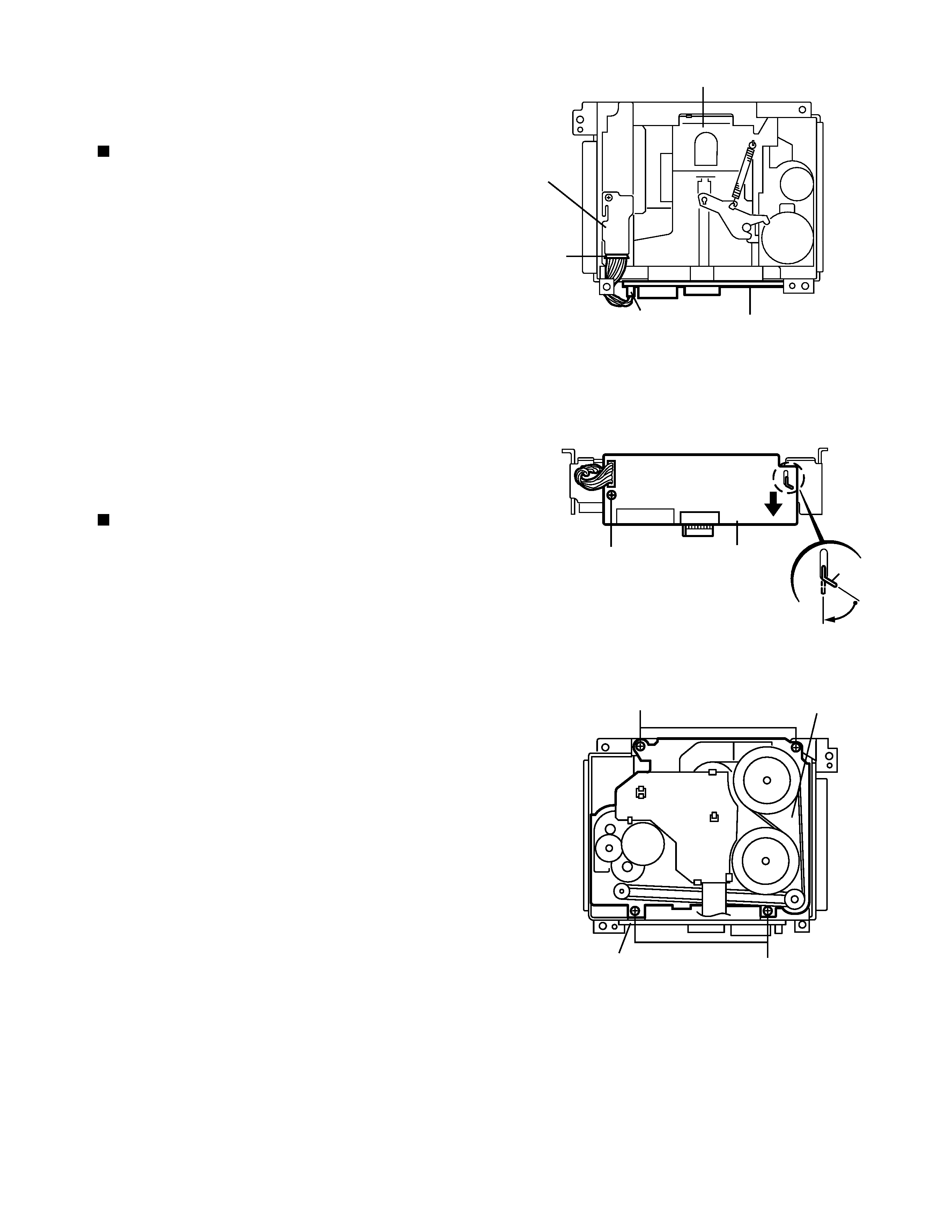
<Removal of the cassette mechanism>
Removing the mecha control P.W.B.
(See Fig.1 and 2)
Disconnect the 6pin harness from connector CN402
and the card wire from CN403 on the mecha control
P.W.B. (Refer to Fig.1 and 2).
Remove the four screws B
on the bottom of the
cassette mechanism.
1.
2.
Removing the cassette mechanism
assembly (See Fig.1 to 3)
Fig.1
Cassette mechanism ass'y
Head relay
P.W.B.
6pin
harness
CN402
CN403
CN402
Mecha control P.W.B.
Fig.2
Tab a
Mecha control P.W.B.
Fig.3
Cassette mechanism ass'y
B
B
A
Mecha control P.W.B.
CN403