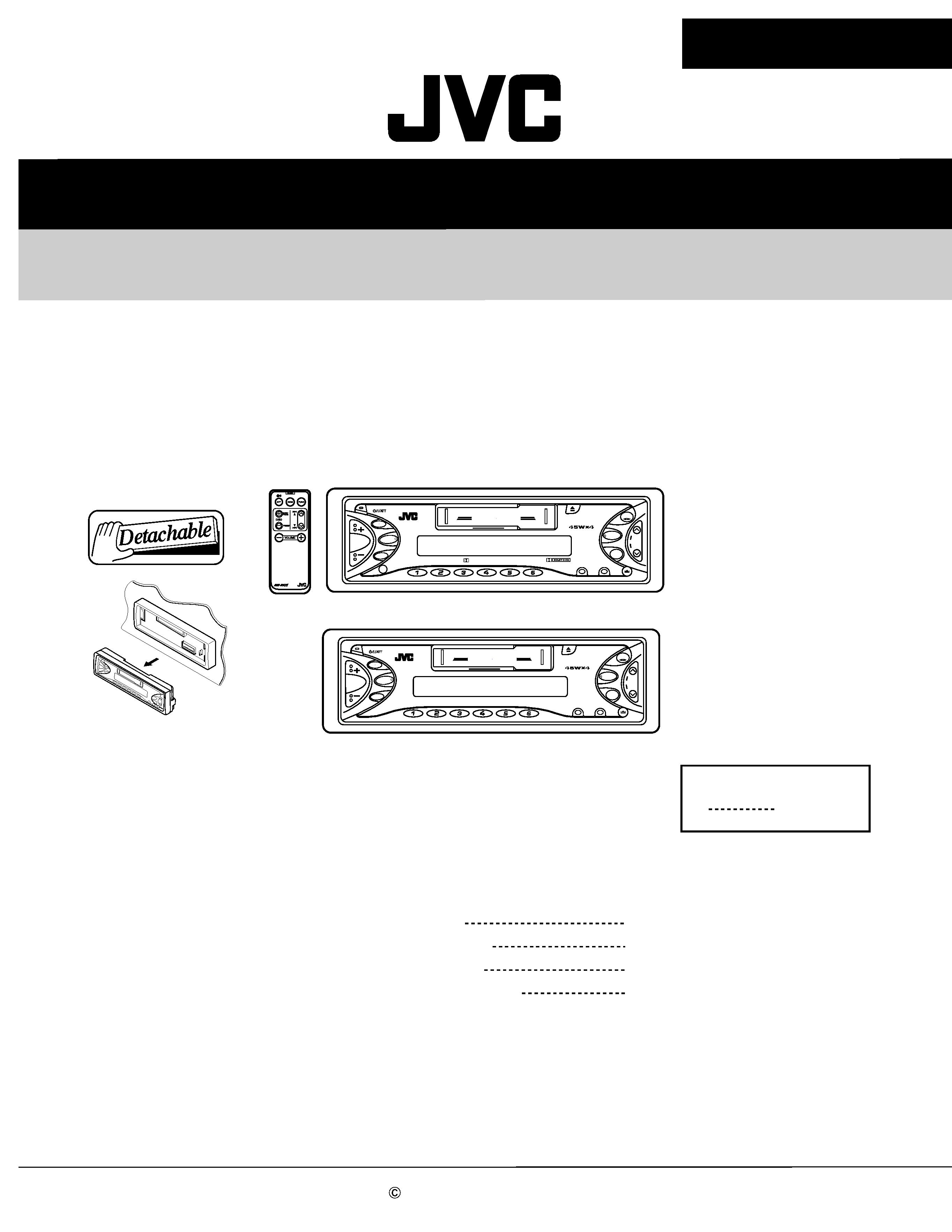
SERVICE MANUAL
CASSETTE RECEIVER
No.49713
Mar. 2002
COPYRIGHT
2002 VICTOR COMPANY OF JAPAN, LTD.
KS-FX711/KS-FX511
KS-FX711/KS-FX511
Area Suffix
U
Other areas
Contents
Safety precaution
Disassembly method
Adjustment method
Description of major ICs
1-2
1-3
1-18
1-22
CD CHANGER CONTROL
SEL
LOUD
DISP
SSM
FM/AM
TAPE
CD-
CH
SCM
MODE
7
8
9
10
11
12 RND
RPT
MO
Multi
Music
Scan
KS-FX711
CD CHANGER CONTROL
SEL
LOUD
DISP
SSM
FM/AM
TAPE
CD-
CH
SCM
MODE
7
8
9
10
11
12 RND
RPT
MO
Multi
Music
Scan
KS-FX511
KS-FX711
KS-FX511
1-2
KS-FX711/KS-FX511
!
Burrs formed during molding may be left over on some parts of the chassis. Therefore,
pay attention to such burrs in the case of preforming repair of this system.
Safety precaution
1-3
KS-FX711/KS-FX511
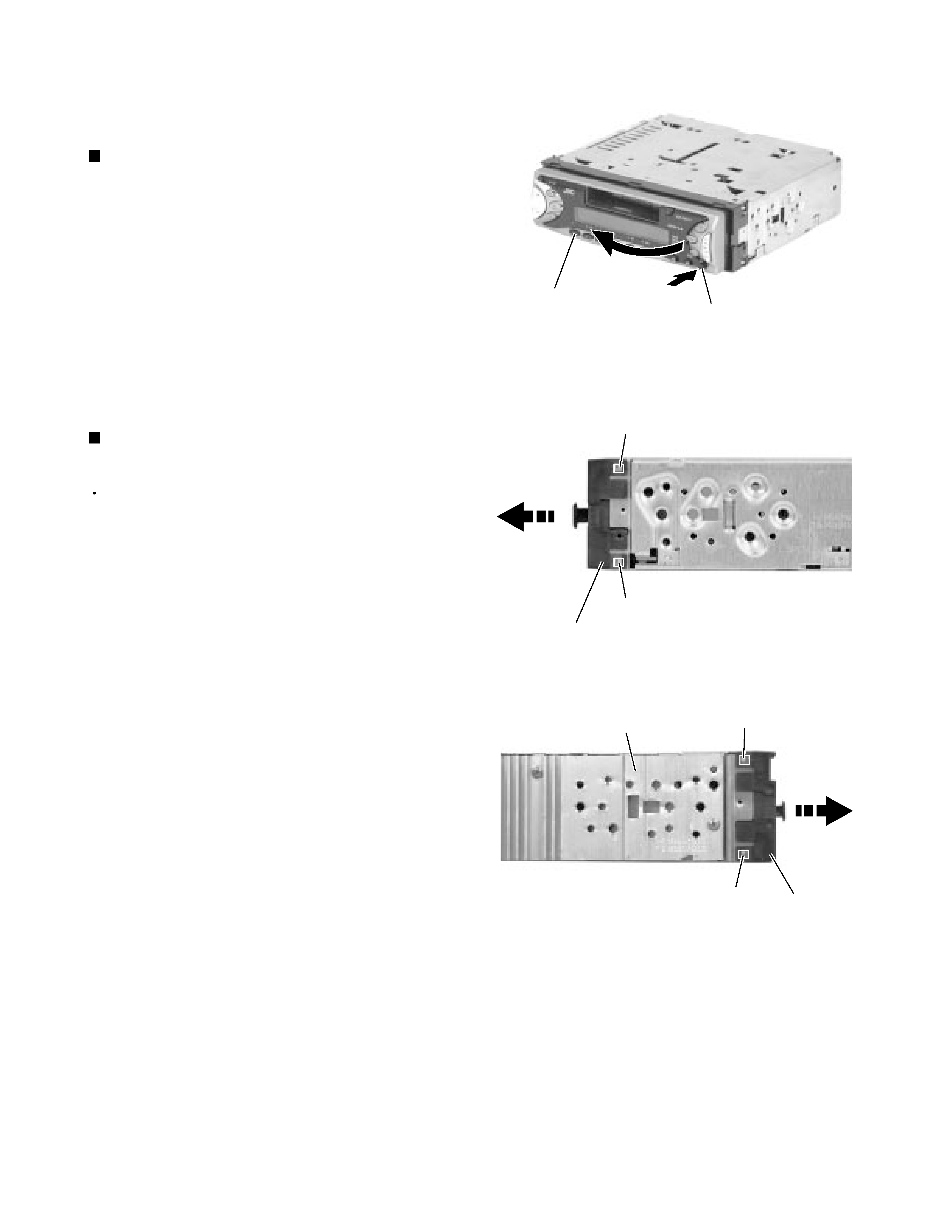
Press the eject button in the lower right part of the
front panel. Remove the front panel assembly from
the body.
1.
Removing the front panel assembly
(See Fig.1)
Prior to performing the following procedure, remove
the front panel assembly.
Release the four joint tabs a on both sides of the
front chassis assembly and remove the front chassis
assembly toward the front.
1.
Removing the front chassis assembly
(See Fig.2 and 3)
Disassembly method
<Main body>
Fig.1
Fig.2
Fig.3
Front panel assembly
Eject button
Tab a
Tab a
Front chassis assembly
Front chassis
assembly
Heat sink
Tab a
Tab a
1-4
KS-FX711/KS-FX511
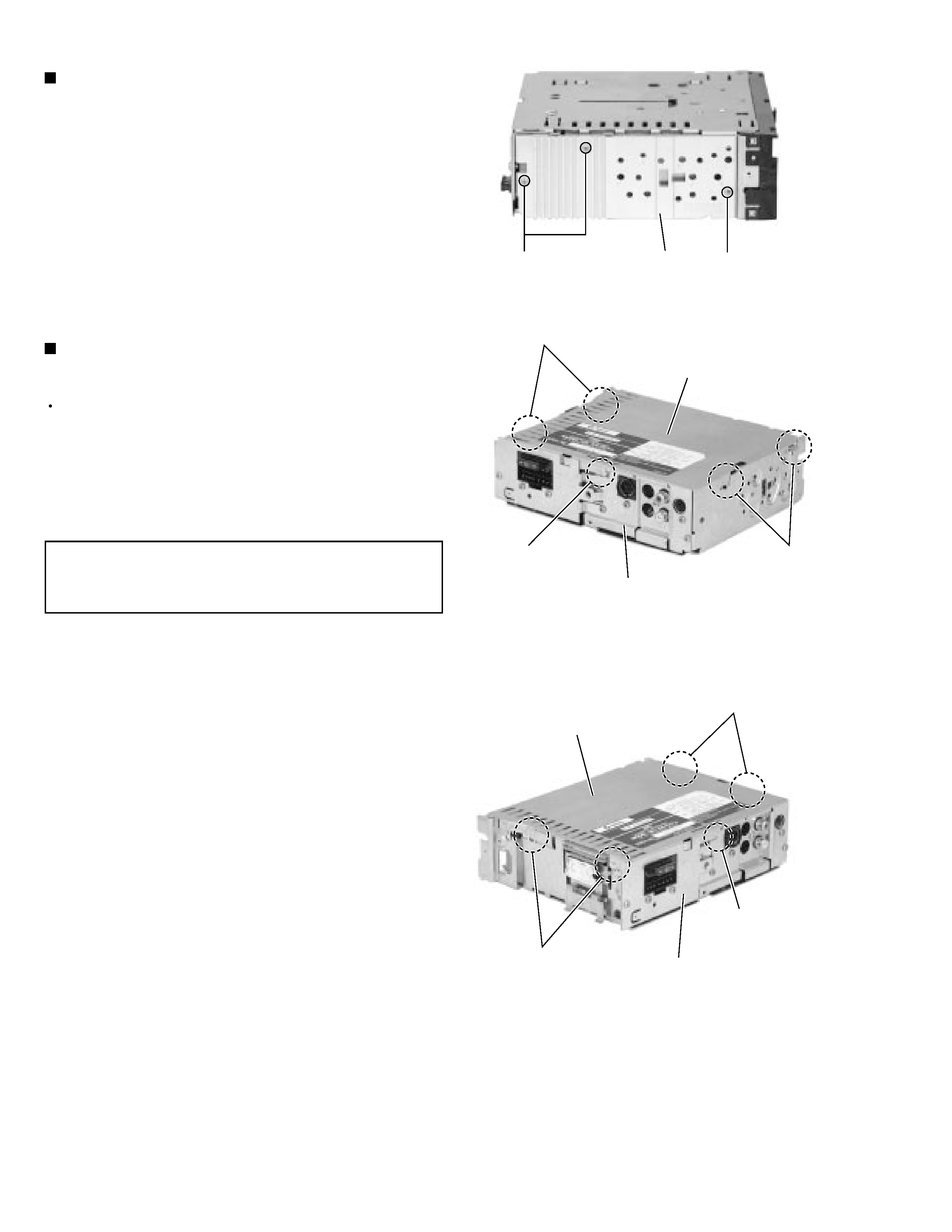
Remove the three screws A on the left side of the
body.
1.
Removing the heat sink (See Fig.4)
Prior to performing the following procedure, remove
the front panel assembly, the front chassis assembly
and the heat sink.
Turn over the body and unjoint the four joints b and
joints c with the bottom cover and the body using a
screwdriver.
1.
Removing the bottom cover
(See Fig.5 and 6)
When disengaging the joint c using a
screwdriver, do not damage or break the
board.
CAUTION:
Fig.4
Fig.5
Fig.6
Heat sink
AA
Joints b
Joints b
Joint c
Joints c
Joints b
Joint c
Bottom cover
Bottom cover
Rear panel
Rear panel
1-5
KS-FX711/KS-FX511
Prior to performing the following procedure, remove
the front panel assembly, the front chassis assembly,
the heat sink and the bottom cover.
Remove the screw B, the five screws C and the two
screws D attaching the rear bracket on the back of
the body. Remove the rear bracket.
1.
Removing the main board
(See Fig.7)
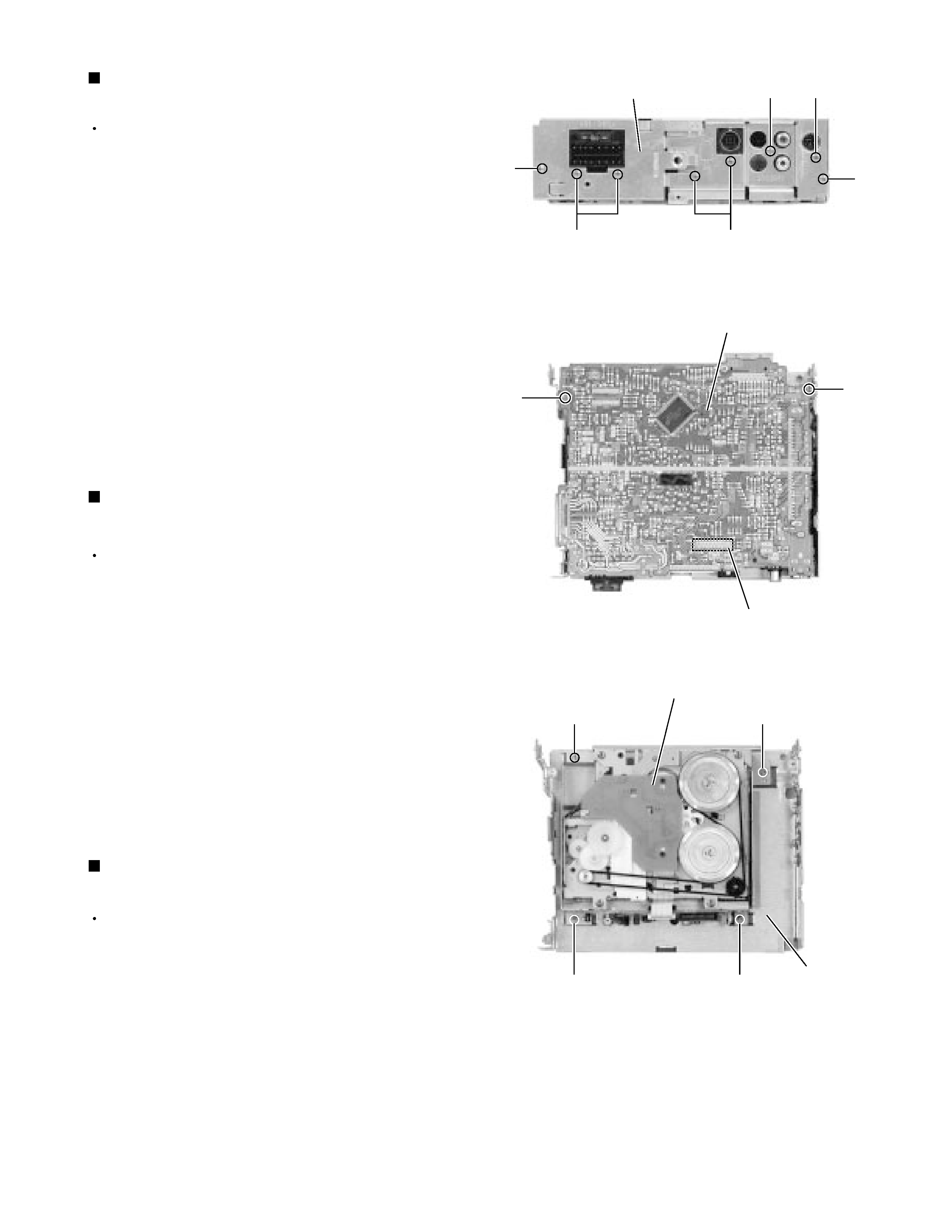
Prior to performing the following procedure, remove
the front chassis, the heat sink, bottom cover and the
main amplifier board assembly.
Remove the four screws F
attaching the cassette
mechanism assembly from the top cover.
1.
Removing the cassette mechanism assembly
(See Fig.9)
Prior to performing the following procedure, remove
the front chassis, the heat sink, bottom cover and the
rear panel.
Remove the two screws E
attaching the main
amplifier board assembly on the top cover.
Disconnect connector CP701 on the main amplifier
board assembly from the cassette mechanism
assembly.
1.
2.
Removing the main amplifier board assembly
(See Fig.8)
Fig.7
Fig.8
Fig.9
Rear bracket
B
D
C
D
C
C
Main board
E
E
CN701
Cassette mechanism assembly
F
F
F
F
Top chassis