SERVICE MANUAL
COPYRIGHT © 2003 VICTOR COMPANY OF JAPAN, LTD.
No.49845
2003/5
CASSETTE RECEIVER
49845
2003
5
KS-FX490
TABLE OF CONTENTS
1
Precautions . . . . . . . . . . . . . . . . . . . . . . . . . . . . . . . . . . . . . . . . . . . . . . . . . . . . . . . . . . . . . . . . . . . . . . . . . . . . 3
2
Disassembly method . . . . . . . . . . . . . . . . . . . . . . . . . . . . . . . . . . . . . . . . . . . . . . . . . . . . . . . . . . . . . . . . . . . . 4
3
Adjustment. . . . . . . . . . . . . . . . . . . . . . . . . . . . . . . . . . . . . . . . . . . . . . . . . . . . . . . . . . . . . . . . . . . . . . . . . . . . 19
4
Description of major ICs . . . . . . . . . . . . . . . . . . . . . . . . . . . . . . . . . . . . . . . . . . . . . . . . . . . . . . . . . . . . . . . . . 23
S
Area Suffix
J ------ Northern America
1-2 (No.49845)
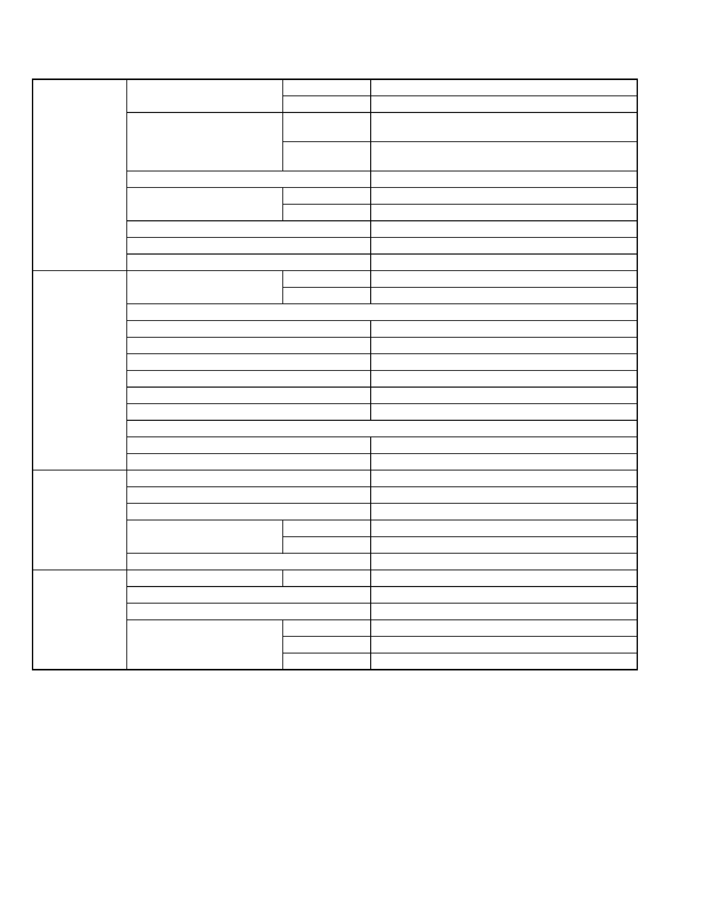
SPECIFICATION
Design and specifications are subject to change without notice.
AUDIO AMPLIFIER
SECTION
Maximum Power Output
Front
50 W per channel
Rear
50 W per channel
Continuous Power Output (RMS) Front
19 W per channel into 4
, 40 Hz to 20 000 Hz at no more
than 0.8 % total harmonic distortion.
Rear
19 W per channel into 4
, 40 Hz to 20 000 Hz at no more
than 0.8 % total harmonic distortion.
Load Impedance
4
(4 to 8 allowance)
Tone Control Range
Bass
±10 dB at 100 Hz
Treble
±9 dB at 10 kHz
Frequency Response
40 Hz to 20 000 Hz
Signal-to-Noise Ratio
70 dB
Line-Out Level/Impedance
2.0 V/20 k
load (250 nWb/m)
TUNER SECTION Frequency Range
FM
87.5 MHz to 107.9 MHz
AM
530 kHz to 1 710 kHz
[FM Tuner]
Usable Sensitivity
11.3 dBf (1.0
µV/75 )
50 dB Quieting Sensitivity
16.3 dBf (1.8
µV/75 )
Alternate Channel Selectivity (400 kHz)
65 dB
Frequency Response
40 Hz to 15 000 Hz
Stereo Separation
35 dB
Capture Ratio
1.5 dB
[AM Tuner]
Sensitivity
20
µV
Selectivity
35 dB
CASSETTE DECK
SECTION
Wow & Flutter
0.11% (WRMS)
Fast-Wind Time
100 sec. (C-60)
Frequency Response (Dolby B NR OFF)
30 Hz to 16 000 Hz (Normal tape)
Signal-to-Noise Ratio
(Normal tape)
(Dolby B NR ON) 65 dB
(Dolby B NR OFF) 56 dB
Stereo Separation
40 dB
GENERAL
Power Requirement
Operating Voltage DC 14.4 V (11 V to 16 V allowance)
Grounding System
Negative ground
Allowable Operating Temperature
0
°C to +40°C (32°F to +104°F)
Dimensions (W
× H × D)
Installation Size
182 mm x 52 mm x 150 mm (7-3/16" x 2-1/16" x 5-15/16")
Panel Size
188 mm x 58 mm x 12 mm (7-7/16" x 2-5/16" x 1/2")
Mass
1.3 kg (2.9 lbs) (excluding accessories)

(No.49845)1-3
SECTION 1
Precautions
1.1
Safety Precautions
!
Burrs formed during molding may be left over on some parts of the chassis. Therefore,
pay attention to such burrs in the case of preforming repair of this system.
1-4 (No.49845)
SECTION 2
Disassembly method
2.1
Main body
2.1.1
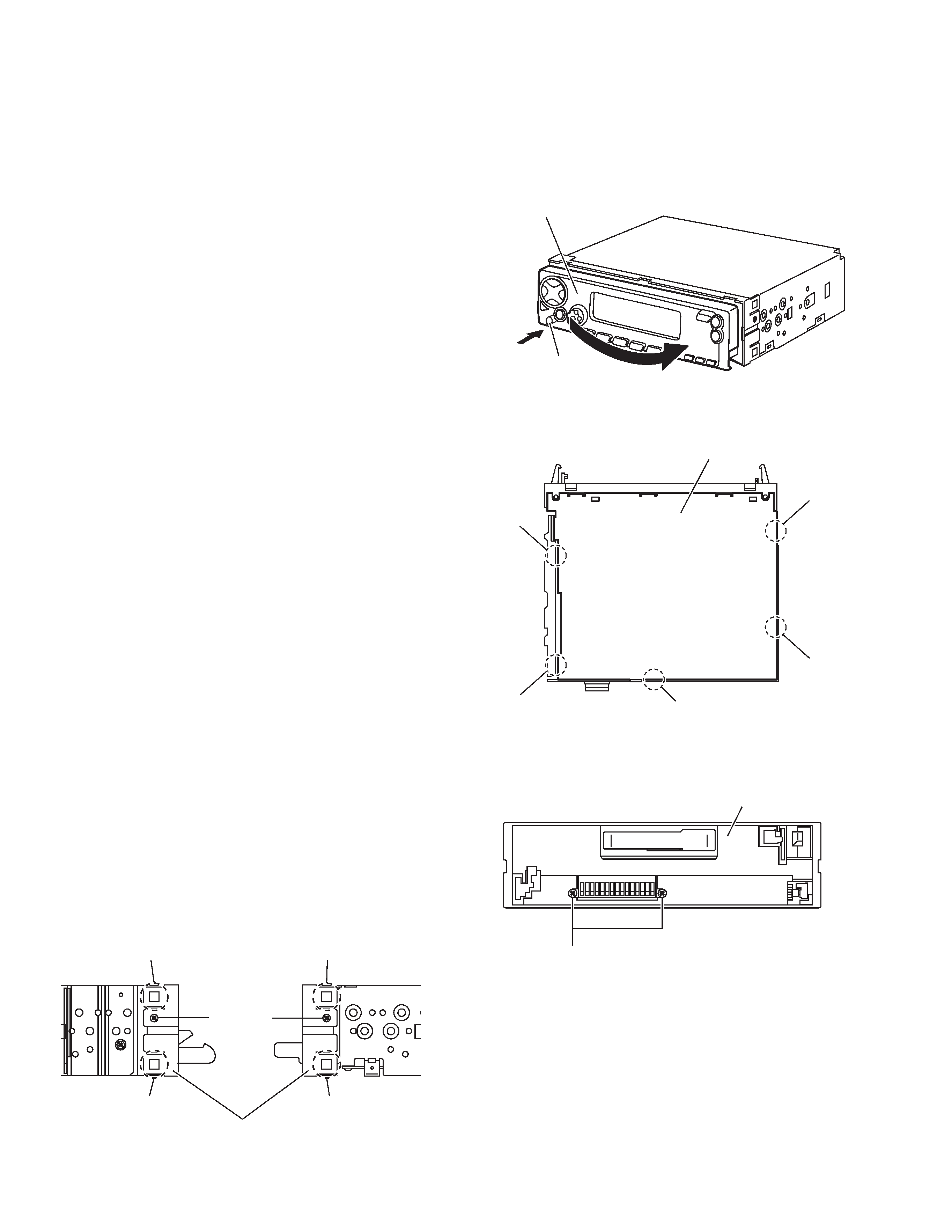
Removing the front panel assembly
(See Fig.1)
(1) Push the detach button in the lower left part of the front
panel assembly and remove the front panel assembly in
the direction of the arrow.
Fig.1
2.1.2 Removing the bottom cover
(See Fig.2)
· Prior to performing the following procedures, remove the front
panel assembly.
(1) Turn the main body upside down.
(2) Insert a screwdriver under the joints to release the two
joints a on the left side, two joints b on the right side and
joint c on the back side of the main body, then remove the
bottom cover from the main body.
CAUTION:
When releasing the joints using a screwdriver, do not damage
the main board.
Fig.2
2.1.3 Removing the front chassis assembly
(See Figs.3 and 4)
· Prior to performing the following procedures, remove the front
panel assembly and bottom cover.
(1) Remove the two screws A on the both sides of the main
body. (See Fig.3.)
(2) Remove the two screws B on the front side of the main
body. (See Fig.4.)
(1) Release the two joints d and two joints e on the both sides
of the main body, then remove the front chassis assembly
toward the front. (See Fig.3.)
Fig.3
Fig.4
Front panel assembly
Detach button
Bottom cover
Joint a
Joint b
Joint a
Joint b
Joint c
Joint d
Joint d
Front chassis assembly
A
Joint e
Joint e
A
B
Front chassis assembly
(No.49845)1-5
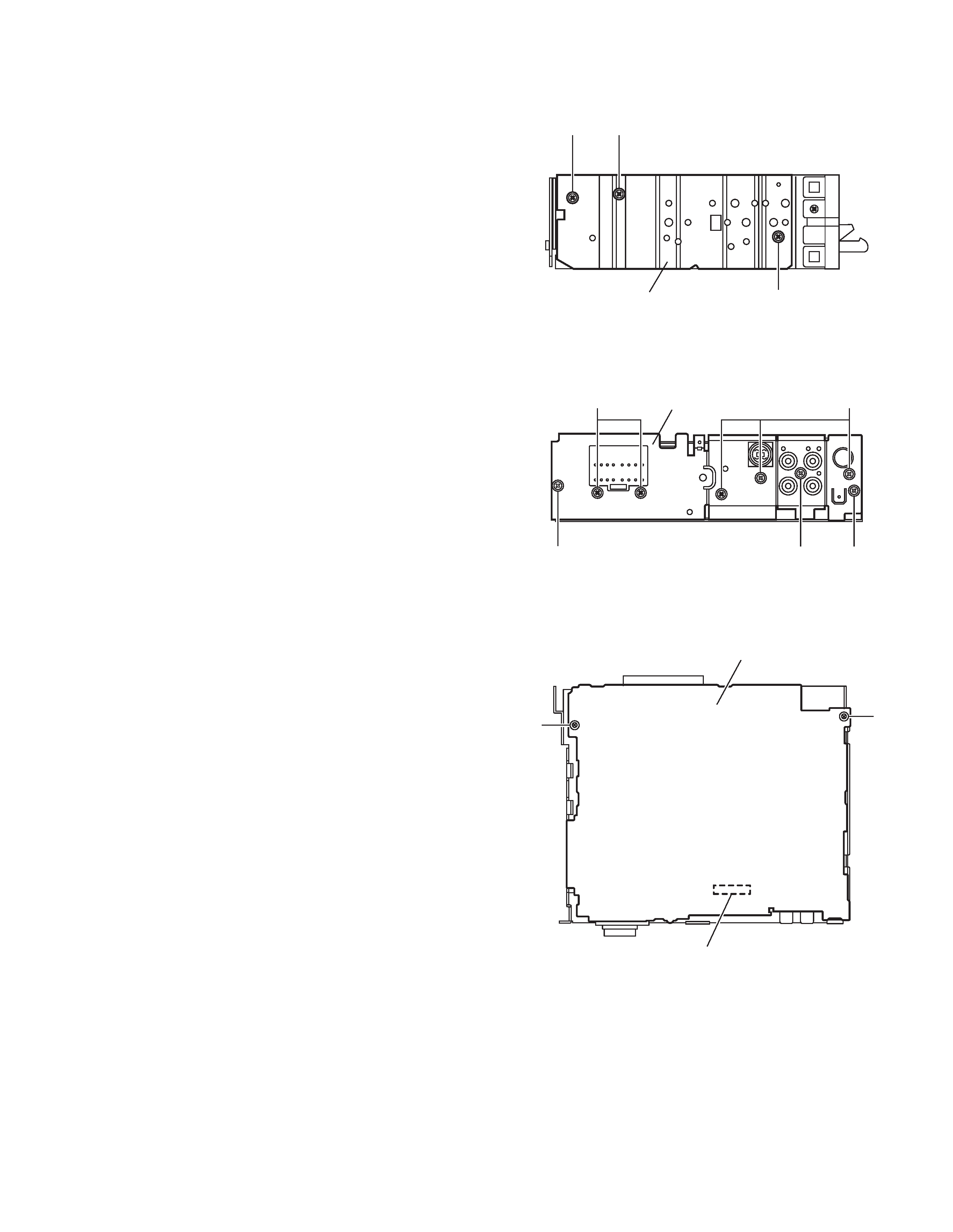
2.1.4
Removing the heat sink
(See Fig.5)
· Prior to performing the following procedure, remove the front
panel assembly.
(1) Remove the two screws C and screw D attaching the heat
sink on the left side of the main body, and remove the heat
sink.
Fig.5
2.1.5 Removing the rear panel
(See Fig.6)
· Prior to performing the following procedure, remove the front
panel assembly and bottom cover.
(1) Remove the two screws E, three screws F and three
screws G attaching the rear panel on the back side of the
main body.
Fig.6
2.1.6 Removing the main board
(See Fig.7)
· Prior to performing the following procedures, remove the front
panel assembly, bottom cover, front chassis assembly, heat
sink and rear panel.
(1) Remove the two screws H attaching the main board on the
top chassis.
(2) Disconnect the connector CP401 on the main board from
the cassette mechanism assembly.
Fig.7
C
D
Heat sink
C
FG
EE
F
Rear bracket
H
Main board
CP401
H