SERVICE MANUAL
CASSETTE RECEIVER
No.49710
Mar. 2002
COPYRIGHT
2002 VICTOR COMPANY OF JAPAN, LTD.
KS-FX480
KS-FX480
Area Suffix
200W
KS-FX480
Multi
Music
Scan
TAPE
SOUND
VOL
VOL
SOURCE
R
F
U
D
ATT
J --------- Northern America
Contents
Safety precaution
Disassembly method
Adjustment method
Description of major ICs
1- 2
1- 3
1-17
1-20~30

KS-FX480
1-2
!
Burrs formed during molding may be left over on some parts of the chassis. Therefore,
pay attention to such burrs in the case of preforming repair of this system.
Safety precaution
KS-FX480
1-3
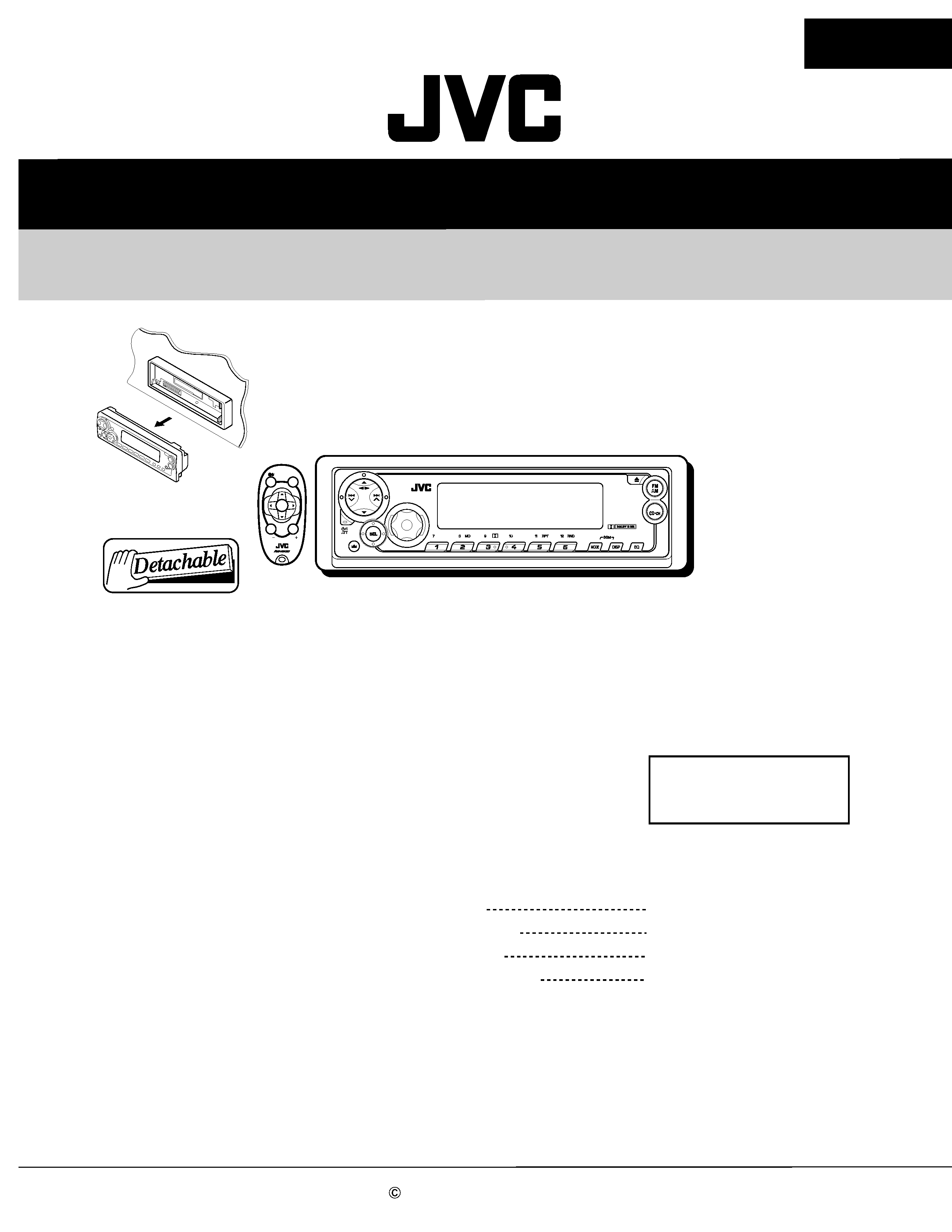
Press the release switch and remove the front panel
unit in the direction of the arrow.
1.
Disassembly method
Removing the front panel unit
(See Fig.1)
Remove the two screws A attaching the front
chassis.
Remove the two screws B on each side of the body.
Release the two joints a and the two joints b on the
sides. Release the two joints c at the bottom and
remove the front chassis toward the front.
1.
2.
3.
Removing the front chassis
(See Fig.2 to 4)
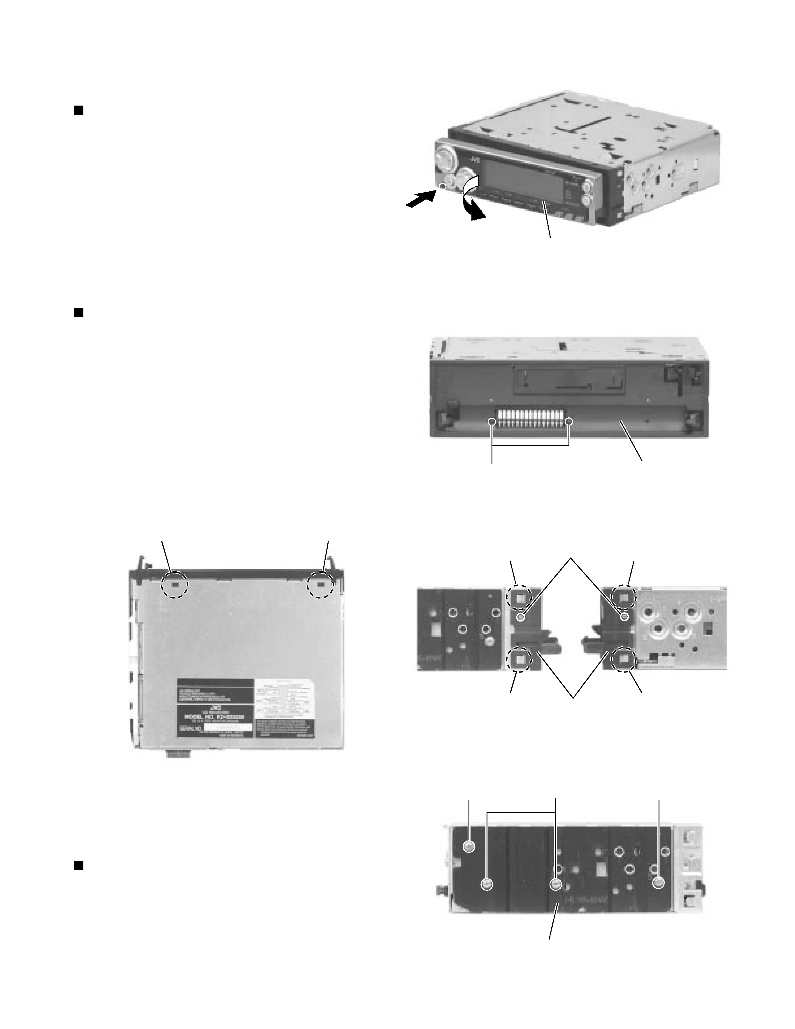
Remove the four screws B attaching the heat sink
on the left side of the body, and remove the heat
sink.
1.
Removing the heat sink (See Fig.5)
Joint c
Heat sink
Fig.2
Fig.1
Fig. 3
Fig.4
Fig. 5
Front panel unit
Front chassis
A
B
Front chassis
Joint a
Joint a
Joint b
Joint b
B
B
B
Joint c
KS-FX480
1-4
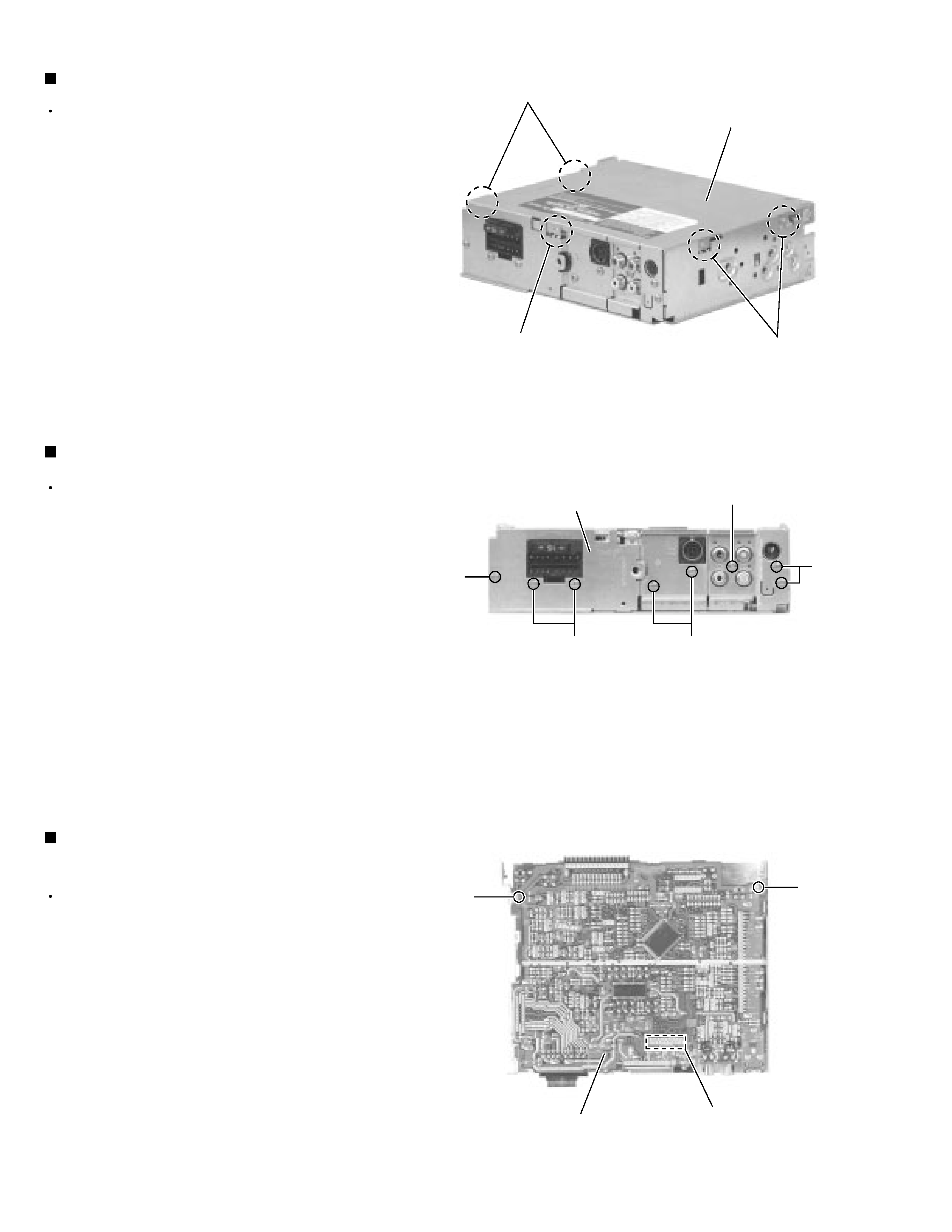
Prior to performing the following procedure, remove
the front chassis and the heat sink.
Turn the body upside down.
Insert a screwdriver to the two joints d and two joints
e on both sides of the body and the joint f on the
back of the body, then detach the bottom cover from
the body.
1.
2.
Removing the bottom cover (See Fig.6)
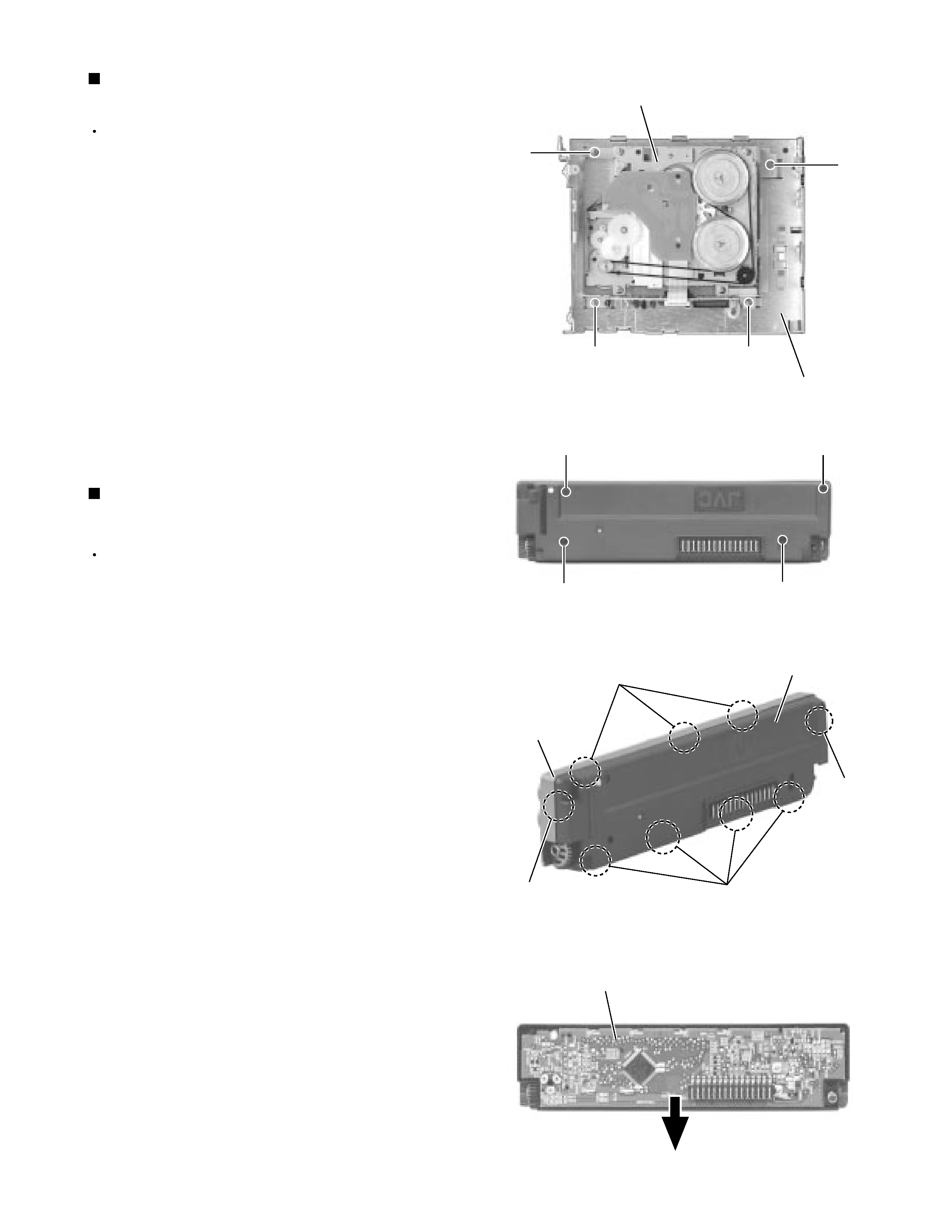
Prior to performing the following procedure, remove
the front chassis, the heat sink and bottom cover.
Remove the eight screws C attaching the rear panel
and one screw D attaching the pine jack on the back
of the body.
1.
Removing the rear panel (See Fig.7 )
Prior to performing the following procedure, remove
the front chassis, the heat sink, bottom cover and the
rear panel.
Remove the two screws E
attaching the main
amplifier board assembly on the top cover.
Disconnect connector CP701 on the main amplifier
board assembly from the cassette mechanism
assembly.
1.
2.
Removing the main amplifier board assembly
(See Fig.8)
Bottom cover
Fig. 6
Fig. 7
Fig. 8
Main board assembly
Joints d
Joints e
Joint f
C
C
C
C
D
Rear panel
CP701
E
E
KS-FX480
1-5
Prior to performing the following procedure, remove
the front chassis, the heat sink, bottom cover and the
main amplifier board assembly.
Remove the four screws F
attaching the cassette
mechanism assembly from the top cover.
1.
Removing the cassette mechanism assembly
(See Fig.9)
Removing the (LCD & key) control switch
board
(See Fig.10 to 12)
Prior to performing the following procedure, remove
the front panel assembly.
Remove the four screws G attaching the rear cover
on the back of the front panel assembly.
Unjoint the nine joints g with the front panel and the
rear cover.
Remove the control switch board on the back of the
front panel.
1.
2.
3.
Cassette mechanism assembly
F
F
Top cover
Fig. 9
G
G
G
G
Fig. 10
Fig. 12
Fig. 11
LCD & Key control board
F
F
Joints g
Joints g
Joints g
Joints g
Front panel
Rear cover