SERVICE MANUAL
COPYRIGHT © 2003 VICTOR COMPANY OF JAPAN, LTD.
No.49770
2003/01
KS-FX220
CASSETTE RECEIVER
49770
2003
01
KS-FX220
TABLE OF CONTENTS
1
Important Safety Precautions . . . . . . . . . . . . . . . . . . . . . . . . . . . . . . . . . . . . . . . . . . . . . . . . . . . . . . . . . . . 1-2
2
Disassembly method . . . . . . . . . . . . . . . . . . . . . . . . . . . . . . . . . . . . . . . . . . . . . . . . . . . . . . . . . . . . . . . . . . 1-3
3
Adjustment method. . . . . . . . . . . . . . . . . . . . . . . . . . . . . . . . . . . . . . . . . . . . . . . . . . . . . . . . . . . . . . . . . . . 1-12
4
Description of major ICs . . . . . . . . . . . . . . . . . . . . . . . . . . . . . . . . . . . . . . . . . . . . . . . . . . . . . . . . . . . . . . . 1-15
Area Suffix
J
Northern America
S.BASS
SEL
DISP
SCM
MO/RND
7
89
10
11
12

KS-FX220
1-2 (No.49770)
SECTION 1
Important Safety Precautions
1.1 Safety Precautions
!
Burrs formed during molding may be left over on some parts of the chassis. Therefore,
pay attention to such burrs in the case of preforming repair of this system.
KS-FX220
(No.49770)1-3
SECTION 2
Disassembly method
2.1 Main body
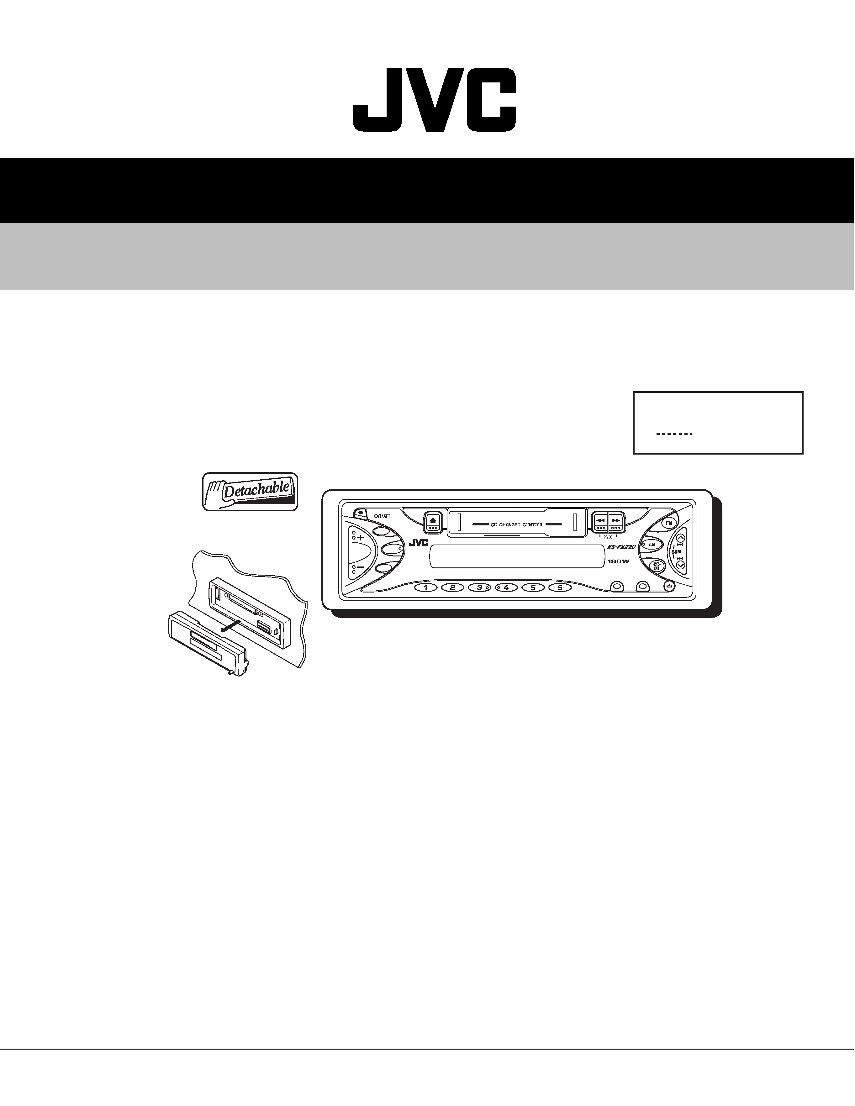
2.1.1 Removing the front panel unit
(See Fig.1)
(1) Press the release switch and remove the front panel unit in
the direction of the arrow.
Fig.1
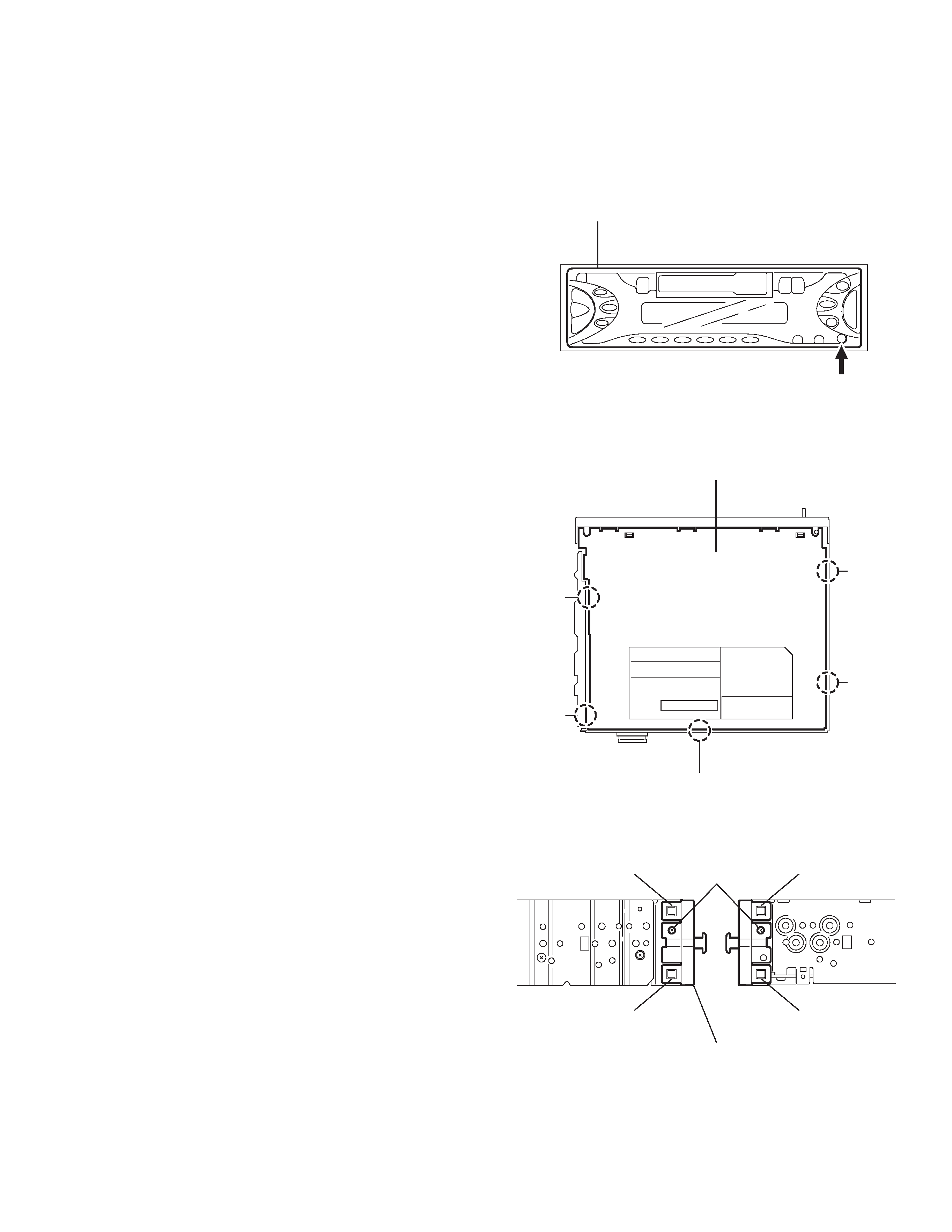
2.1.2 Removing the bottom cover
(See Fig.2)
(1) Turn the body upside down.
(2) Insert a screwdriver to the two joints a and two joints b on
both sides of the body and the joint c on the back of the
body, then detach the bottom cover from the body.
CAUTION:
When disengaging the joint c using a screwdriver, do not dam-
age or break the board.
Fig.2
2.1.3 Removing the front chassis
(See Fig.3)
· Prior to performing the following procedure, remove the bottom
cover.
(1) Remove the two screws A on each side of the body.
(2) Release the two joints d and the two joints e on the sides.
remove the front chassis toward the front.
Fig.3
Front panel assembly
Eject button
Bottom cover
Joint b
Joint b
Joint c
Joint a
Joint a
Joint d
Joint e
Front chassis
Joint d
A
Joint e
KS-FX220
1-4 (No.49770)
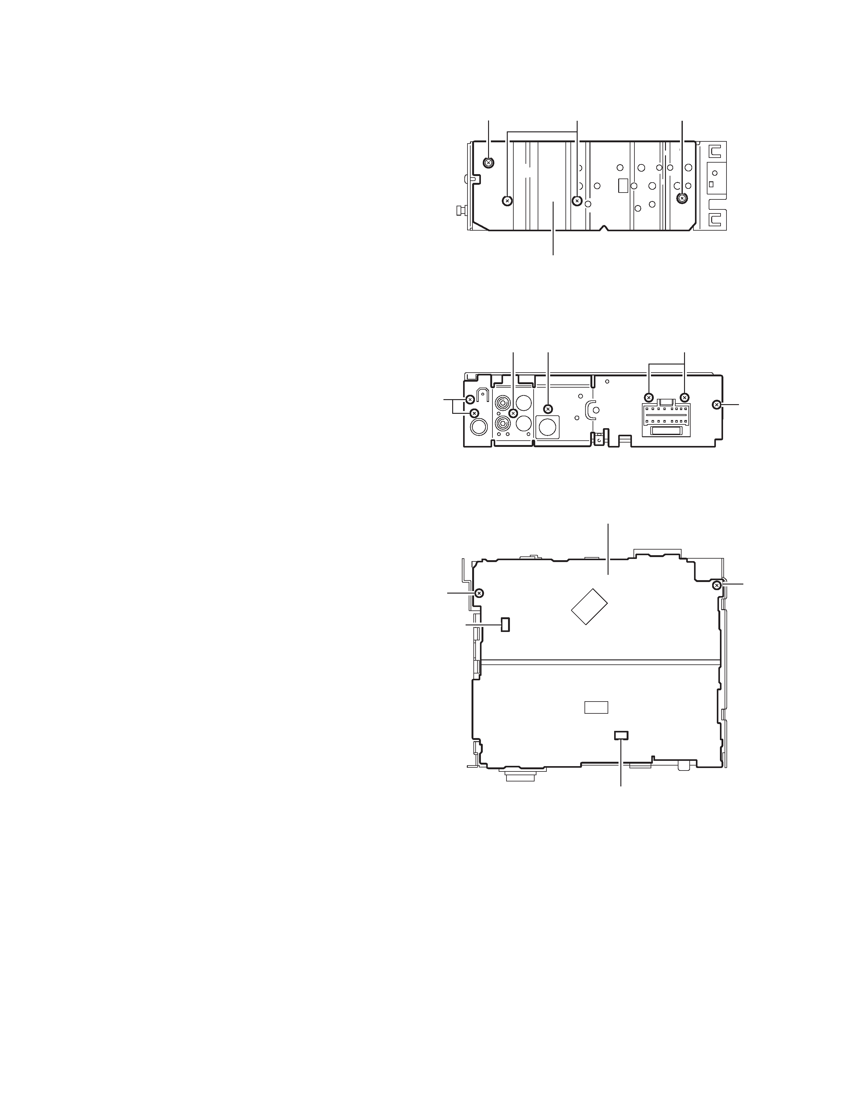
2.1.4
Removing the heat sink
(See Fig.4)
(1) Remove the four screws B attaching the heat sink on the
left side of the body, and remove the heat sink.
Fig.4
2.1.5
Removing the rear panel
(See Fig.5 )
· Prior to performing the following procedure, remove the front
chassis, the heat sink and bottom cover.
(1) Remove the four screws C attaching the rear panel and
three screw D attaching the pine jack on the back of the
body.
Fig.5
2.1.6
Removing the main amplifier board assembly
(See Fig.6)
· Prior to performing the following procedure, remove the front
chassis, the heat sink, bottom cover and the rear panel.
(1) Remove the two screws E attaching the main amplifier
board assembly on the top cover.
(2) Disconnect connector CN901,CN721 on the main amplifier
board assembly from the cassette mechanism assembly.
Fig.6
Heat sink
BB
B
C
C
C
DD
E
E
Main board assembly
CN901
CN721
KS-FX220
(No.49770)1-5
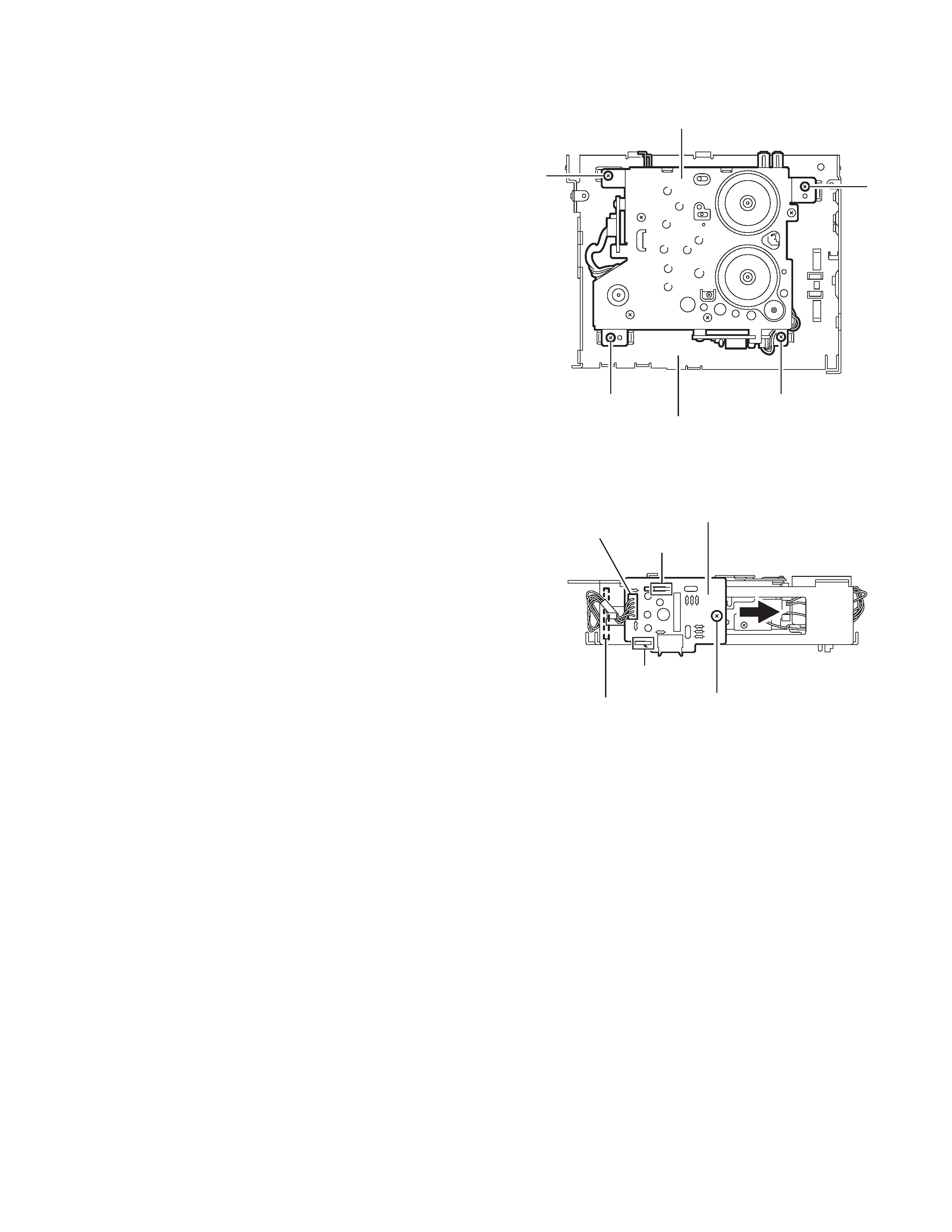
2.1.7 Removing the cassette mechanism assembly
(See Fig.7)
· Prior to performing the following procedure, remove the front
chassis, the heat sink, bottom cover and the main amplifier
board assembly.
(1) Remove the four screws F attaching the cassette mecha-
nism assembly from the top cover.
Fig.7
2.1.8 Removing the head amplifier board
(See Fig.8)
· Prior to performing the following procedure, remove the front
chassis, the bottom cover, the heat sink, the main board as-
sembly and the cassette mechanism assembly.
(1) Remove the screw G attaching the head amplifier board.
(2) Move the head amplifier board in the direction of the arrow
to release the two joints f and remove.
(3) Disconnect the wire from CJ901 on the head amplifier
board.
Fig.8
F
F
F
F
Top chassis
Cassette mechanism
joint f
G
CJ901
Head amplifier board
To head relay board
joint f