SERVICE MANUAL
COPYRIGHT © 2003 VICTOR COMPANY OF JAPAN, LTD.
No.49809
2003/03
KS-AX7700
POWER AMPLIFIER
49809
2003
03
KS-AX7700
TABLE OF CONTENTS
1
Important Safety Precautions . . . . . . . . . . . . . . . . . . . . . . . . . . . . . . . . . . . . . . . . . . . . . . . . . . . . . . . . . . . 1-2
2
Disassembly method . . . . . . . . . . . . . . . . . . . . . . . . . . . . . . . . . . . . . . . . . . . . . . . . . . . . . . . . . . . . . . . . . . 1-3
3
Adjustment. . . . . . . . . . . . . . . . . . . . . . . . . . . . . . . . . . . . . . . . . . . . . . . . . . . . . . . . . . . . . . . . . . . . . . . . . . . 1-6
Area suffix
J ------------ Northern America
KS-AX7700
1-2 (No.49809)
SECTION 1
Important Safety Precautions
1.1 Safety Precautions
!
Burrs formed during molding may be left over on some parts of the chassis. Therefore,
pay attention to such burrs in the case of preforming repair of this system.
KS-AX7700
(No.49809)1-3
SECTION 2
Disassembly method
CAUTION:
If electricity is connected during disassembly, it must be a no
load current.
If it is load current, be sure to attach a heat sink to the power-
amp IC.
This will be damaged if the above precautions are not followed,
as it does not have a sub heat sink attached to it.
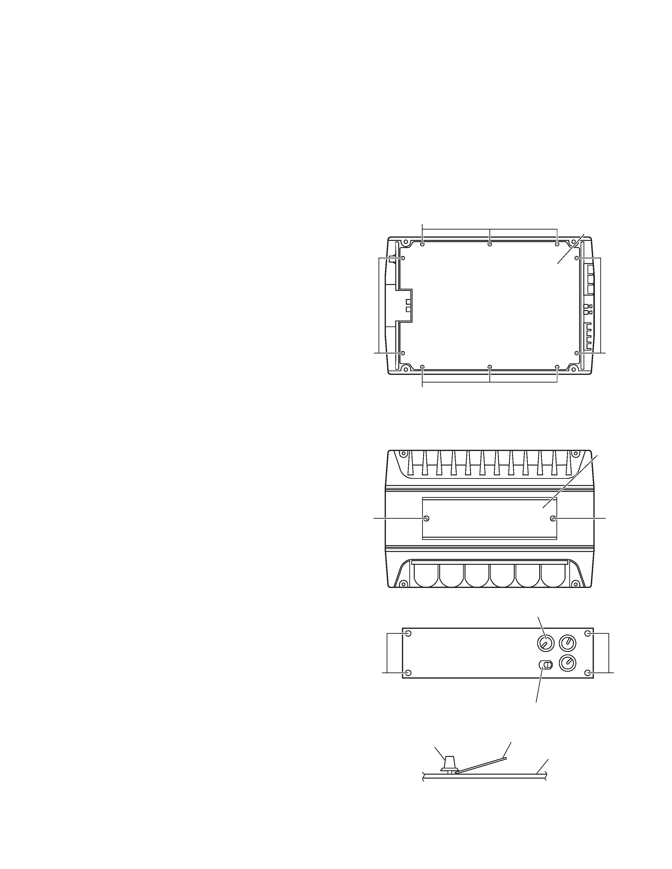
2.1 Removing the bottom cover (see Fig. 1)
(1) From the bottom side of the main unit, remove the 4 screws
A retaining the bottom cover.
(2) Then remove the 6 screws B retaining the bottom cover.
(3) Remove the bottom cover.
Fig.1
2.2 Removing the main board (see Fig. 2 to 8)
(1) Remove the bottom cover from the main unit.
(2) Loosen and remove the 2 screws C retaining the top plate
on the main unit.
(Stoppers are attached to the backs of the C screws so that
they cannot be removed easily.)
(3) Remove the 3 volume knobs on top of the control panel. If
it cannot be pulled out easily, insert a scale or suitable lever
between the base of the volume knob and the control panel
so that the volume knob is raised a little above the surface
and then remove it.
(Be careful when inserting a lever etc. not to scratch
the surface of the control panel).
(4) Remove the 4 screws D retaining the control panel. Then
detach the control panel and the switch knob.
Fig.2
Fig.3
Fig.4
Bottom cover
B
A
A
B
Top plate
C
C
DD
Volume knob
Switch knob
(Side view)
Scale or suitable lever
Volume knob
Control panel
KS-AX7700
1-4 (No.49809)
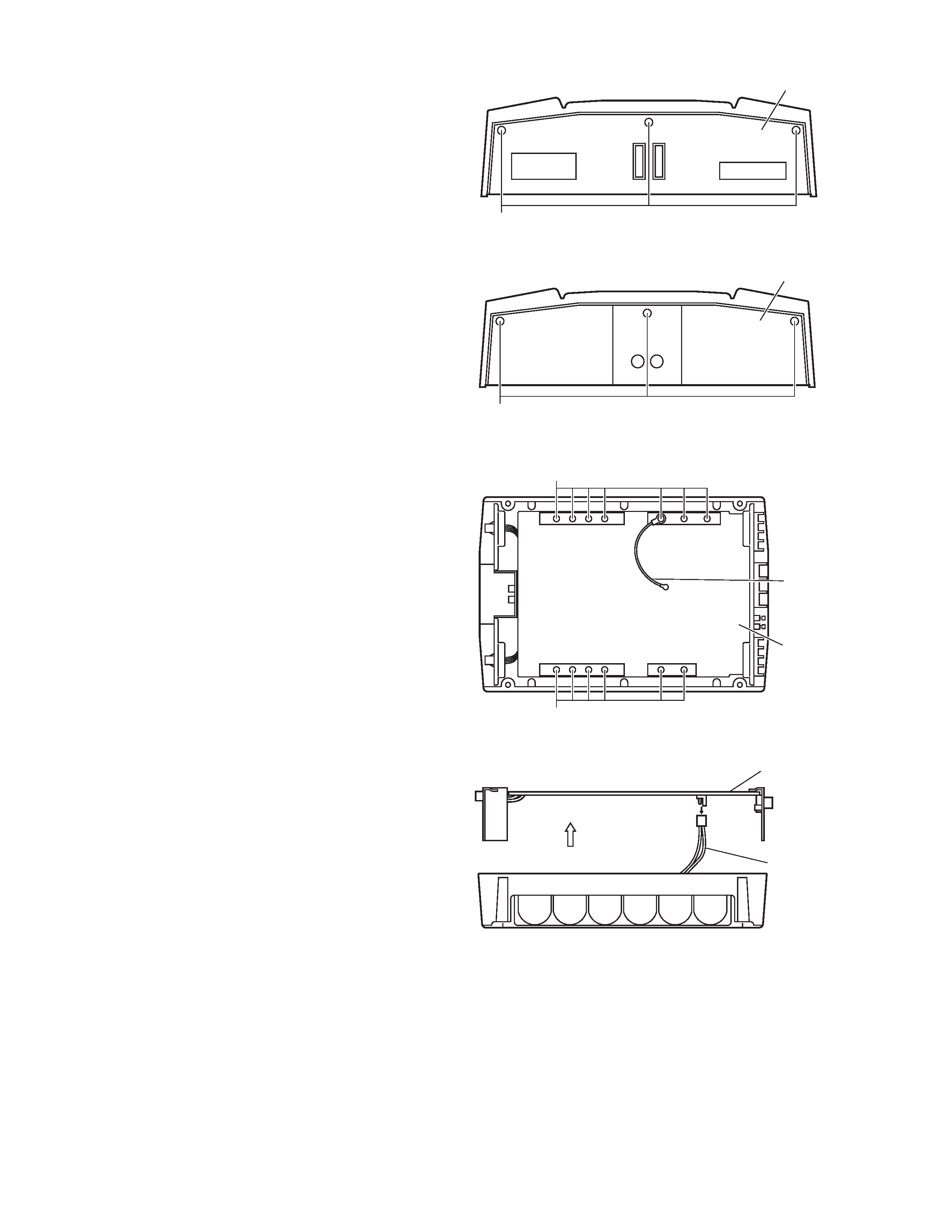
(5) Remove the 6 screws E retaining the panels on both sides
of the main unit.
(6) Remove the 13 screws F attaching the main board to the
bottom of the main unit.
(The GND wire that protrudes from the main board
must be re-installed to its original position during re-
assembly.)
(7) To remove the wire ass'y, lift up the main board a little.
Fig.5
Fig.6
Fig.7
Fig.8
Rear panel
E
Front panel
E
GND wire
Main board
F
F
Main board
Wire assemb'y
(Side view)
KS-AX7700
(No.49809)1-5
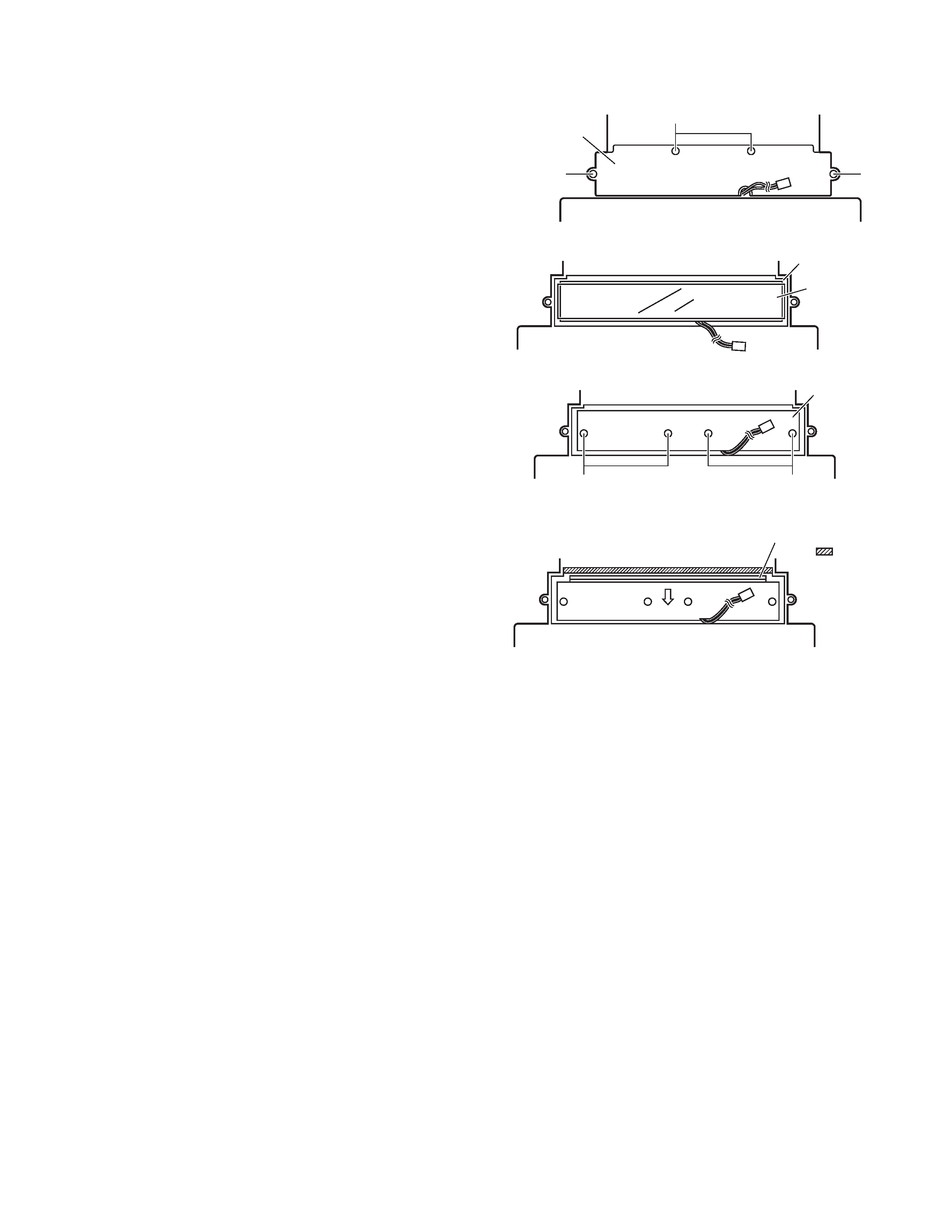
2.3 Removing the CCFL board (see Fig. 9 to 12)
(1) Remove the bottom cover.
(2) Then remove the Main board.
(3) From the bottom side of the main unit, remove the 4 screws
G retaining the CCFL cover.
(4) Then remove the insulation sheet on top of the CCFL
board.
(5) Remove the 4 screws H retaining the CCFL board.
(6) Remove the CCFL board by sliding it a little towards the
arrow mark.
Fig.9
Fig.10
Fig.11
Fig.12
CCFL cover
G
G
G
CCFL board
Insulation sheet
H
CCFL board
H
This section is cought
by the
portion.