SERVICE MANUAL
KS-AX6700
KS-AX6700
No. 49559
Jun. 2000
KS-AX6700
POWER AMPLIFIER
Printed in Japan
200006(S)
(No. 49559)
Contents
Safety Precaution
Location of main parts
Removal of main parts
Adjustment method
Wire connection diagram
1-2
1-3
1-5
1-8
1-9
VICTOR COMPANY OF JAPAN, LIMITED
MOBILE ELECTRONICS DIVISION
PERSONAL & MOBILE NETWORK B.U. 10-1,1Chome,Ohwatari-machi,Maebashi-city,Japan
COPYRIGHT
2000 VICTOR COMPANY OF JAPAN, LTD.
This service manual is printed on 100% recycled paper.
Areas suffix
Caution
If electricity is connected during disassembly, it must be a no load current. If it is load
current, be sure to attach a heat sink to the power-amp IC. This will be damaged if the
above precautions are not followed, as it does not have a sub heat sink attached to it.
J -------- Nothem America
E ----- Continental Europe

KS-AX6700
1-2
Safety precaution
! CAUTION Burrs formed during molding may be left over on some parts of the chassis. Therefore,
pay attention to such burrs in the case of preforming repair of this system.
KS-AX6700
1-3
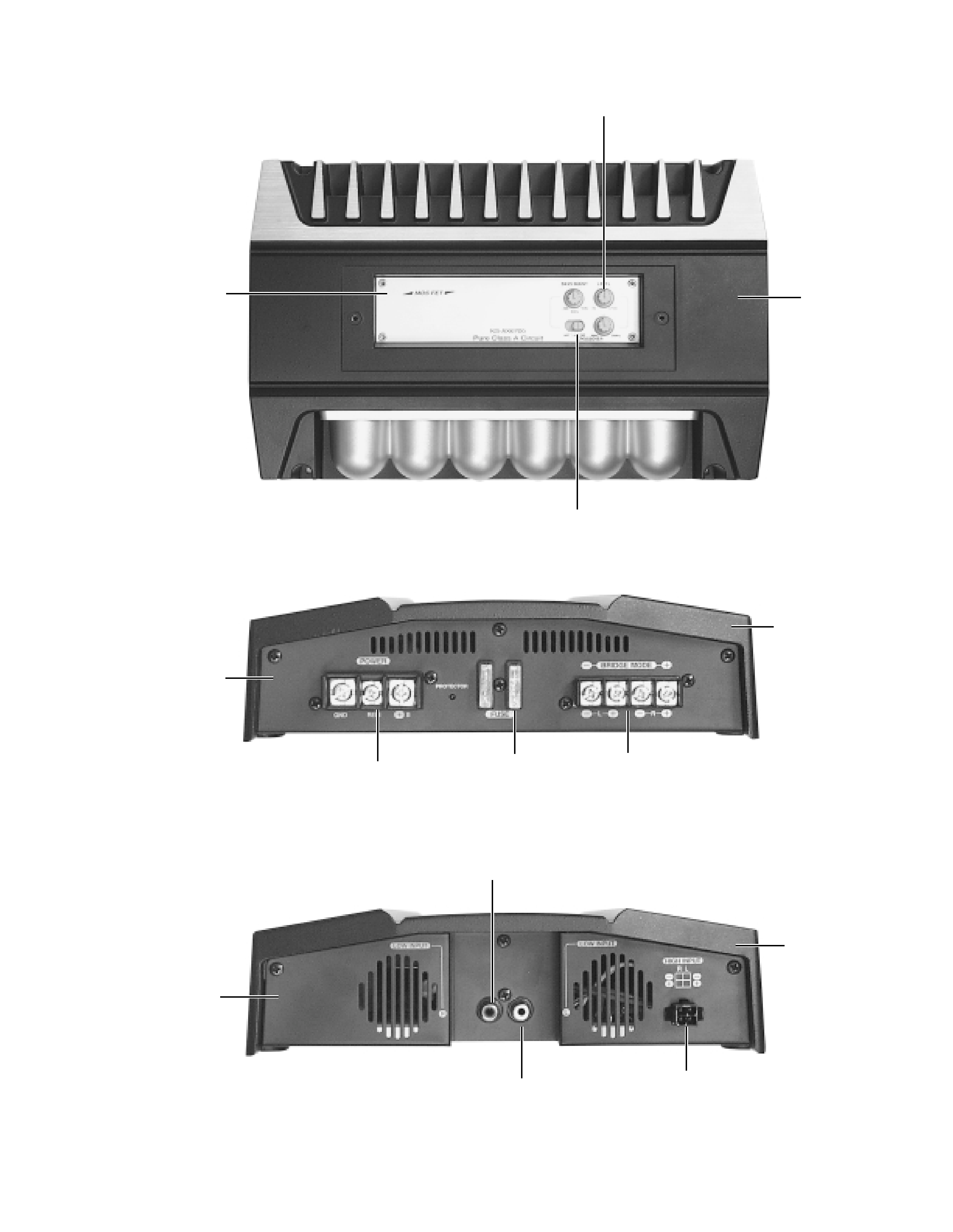
Location of main parts
Volume knob
Control panel
Switch knob
Heat sink
Rear panel
Input for power
Fuse
Output terminal
Heat sink
Front panel
Low input(L)
High input connector
Heat sink
Low input(R)
KS-AX6700
1-4
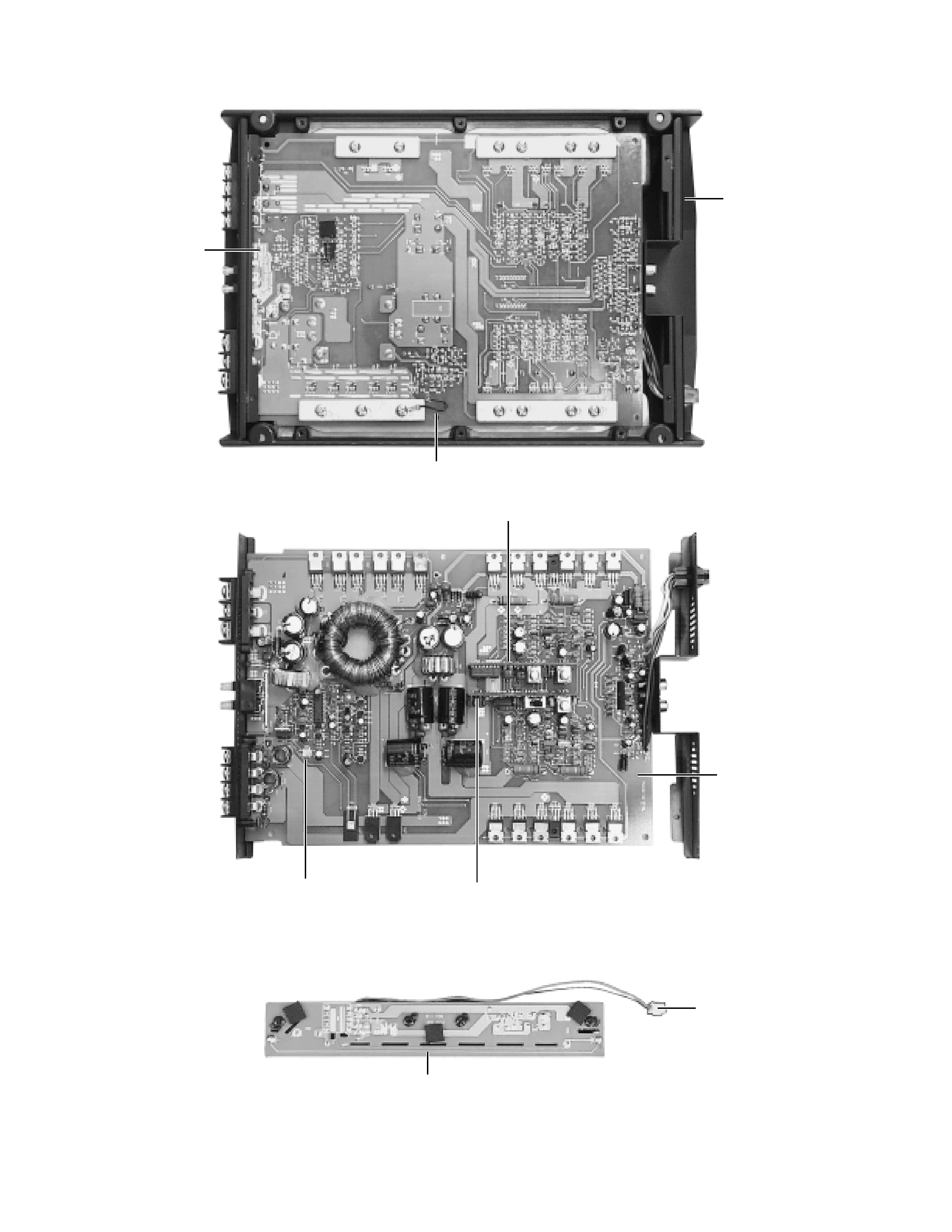
CCFL P.C. board
Wire assemb'y
(from Main)
Main P.C. board
GND wire
Heat sink
(Bottom view)
Sub1 P.C. board
Main P.C. board
Sub2 P.C. board
2pin connector
(to CCFL P.C. board)
KS-AX6700
1-5
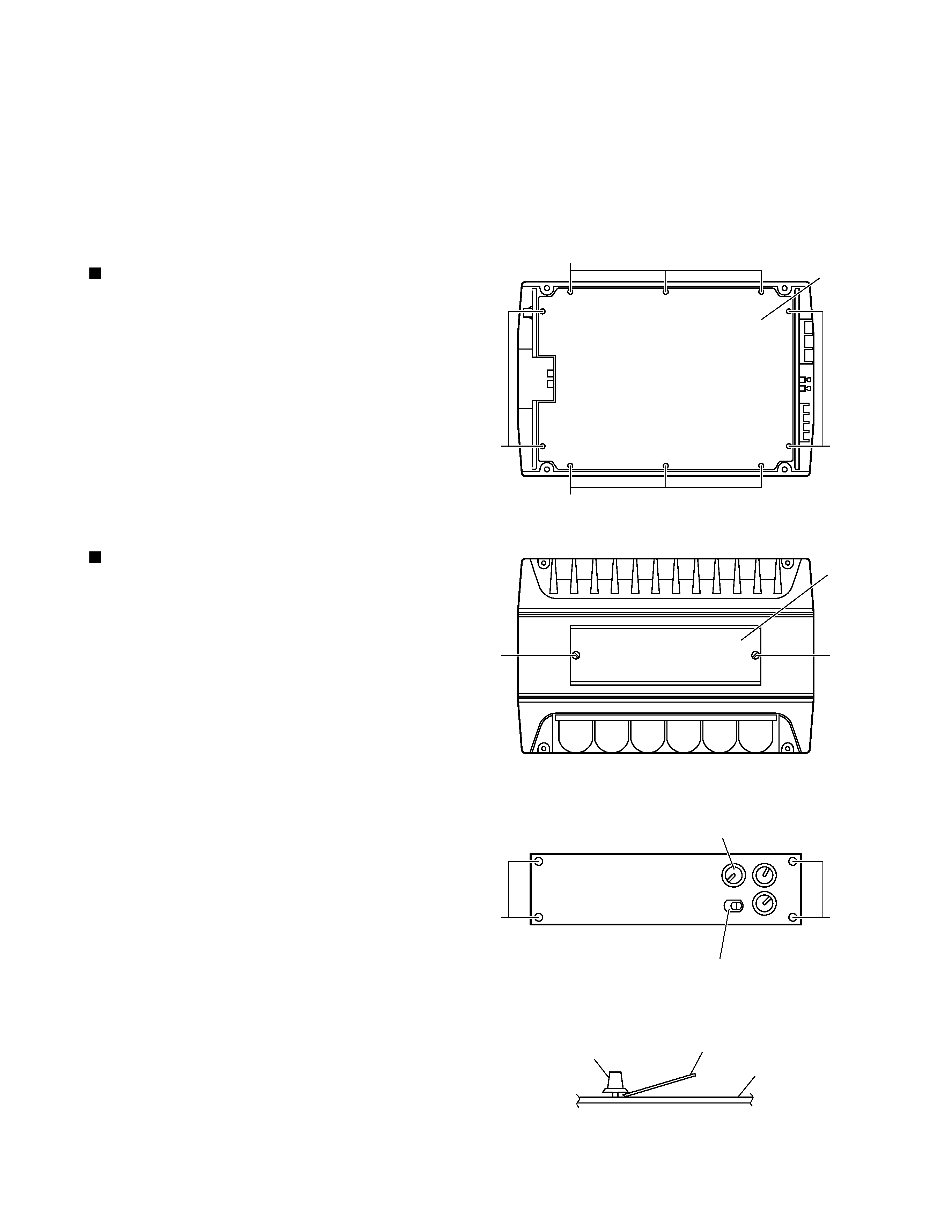
From the bottom side of the main unit, remove the 4
screws A retaining the bottom cover.
Then remove the 6 screws B retaining the bottom
cover.
Remove the bottom cover.
1.
2.
3.
If
electricity
is
connected
during
disassembly, it must be a no load current. If
it is load current, be sure to attach a heat
sink to the power-amp IC. This will be
damaged if the above precautions are not
followed, as it does not have a sub heat
sink attached to it.
CAUTION:
Removal of main parts
Removing the bottom cover (see Fig. 1)
Remove the bottom cover from the main unit.
Loosen and remove the 2 screws C retaining the top
plate on the main unit. (Stoppers are attached to the
backs of the C screws so that they cannot be
removed easily.)
1.
2.
Remove the 3 volume knobs on top of the control
panel. If it cannot be pulled out easily, insert a scale
or suitable lever between the base of the volume
knob and the control panel so that the volume knob is
raised a little above the surface and then remove it.
(Be careful when inserting a lever etc. not to
scratch the surface of the control panel).
Remove the 4 screws D retaining the control panel.
Then detach the control panel and the switch knob.
3.
4.
Removing the main P.C. board
(see Fig. 2 to 8)
(Side view)
Scale or suitable lever
D
Top plate
C
Volume knob
Control panel
Bottom cover
B
Fig. 1
Fig. 3
Fig. 2
Fig. 4
A
D
C
A
B
Volume knob
Switch knob