SERVICE MANUAL
COPYRIGHT © 2003 VICTOR COMPANY OF JAPAN, LTD.
No.49782
2003/02
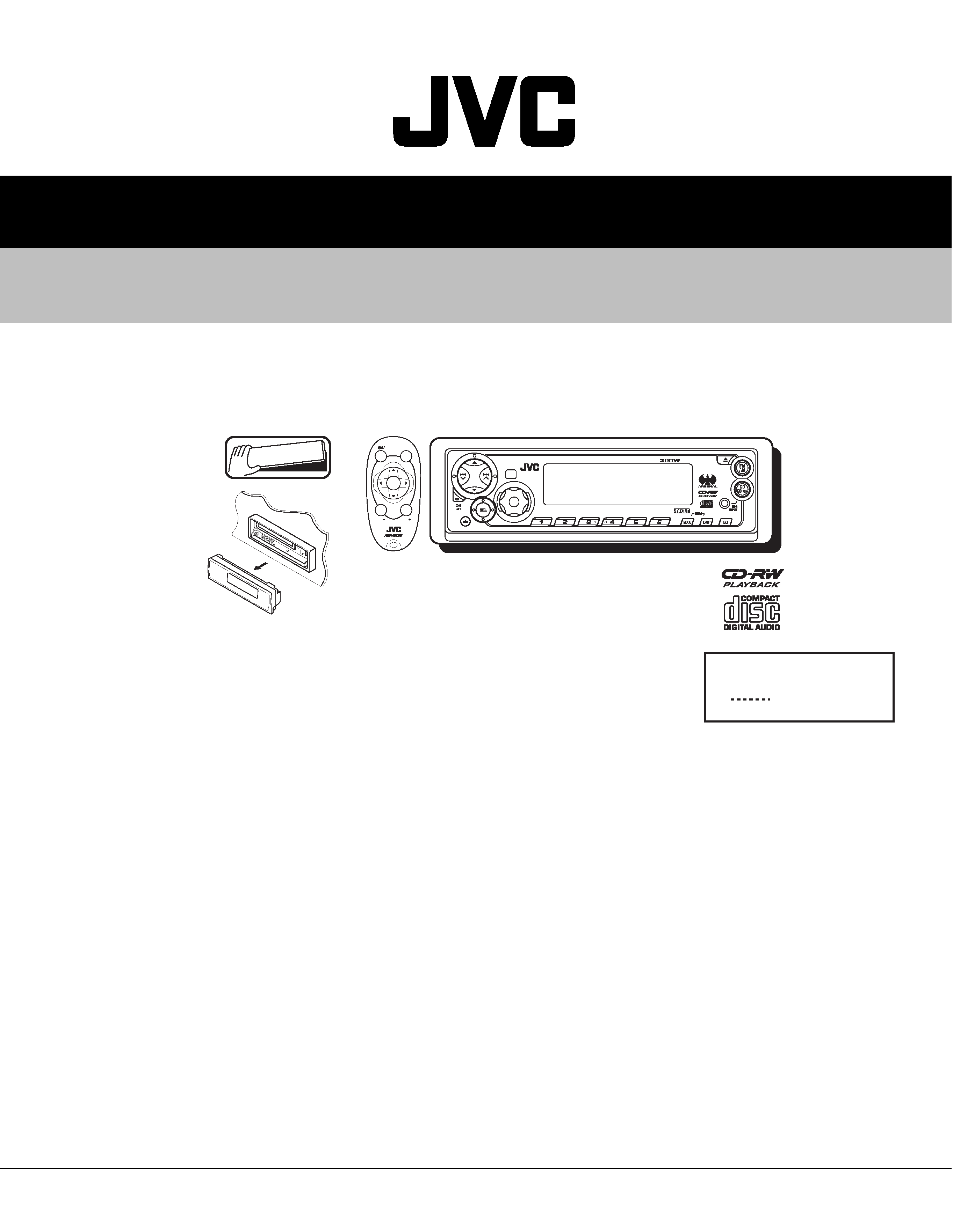
KD-SX8350
CD RECEIVER
49782
2003
01
KD-SX8350
TABLE OF CONTENTS
1
Important Safety Precautions . . . . . . . . . . . . . . . . . . . . . . . . . . . . . . . . . . . . . . . . . . . . . . . . . . . . . . . . . . . 1-2
2
Disassembly method . . . . . . . . . . . . . . . . . . . . . . . . . . . . . . . . . . . . . . . . . . . . . . . . . . . . . . . . . . . . . . . . . . 1-4
3
Adjustment. . . . . . . . . . . . . . . . . . . . . . . . . . . . . . . . . . . . . . . . . . . . . . . . . . . . . . . . . . . . . . . . . . . . . . . . . . 1-23
4
Description of major ICs . . . . . . . . . . . . . . . . . . . . . . . . . . . . . . . . . . . . . . . . . . . . . . . . . . . . . . . . . . . . . . . 1-27
KD-SX8350
9
8
7
9
MO
INT
RPT
11
10
RND
12
Detachable
SOUND
VOL
VOL
SOURCE
R
F
U
D
ATT
Area Suffix
J
Northern America
KD-SX8350
1-2 (No.49782)
SECTION 1
Important Safety Precautions
1.1 Safety Precautions
!
Burrs formed during molding may be left over on some parts of the chassis. Therefore,
pay attention to such burrs in the case of preforming repair of this system.
!
Please use enough caution not to see the beam directly or touch it in case of an
adjustment or operation check.
KD-SX8350
(No.49782)1-3
1.2 Preventing static electricity
Electrostatic discharge (ESD), which occurs when static electricity stored in the body, fabric, etc. is discharged,
can destroy the laser diode in the traverse unit (optical pickup). Take care to prevent this when performing repairs.
1.2.1
Grounding to prevent damage by static electricity
Static electricity in the work area can destroy the optical pickup (laser diode) in devices such as DVD players.
Be careful to use proper grounding in the area where repairs are being performed.
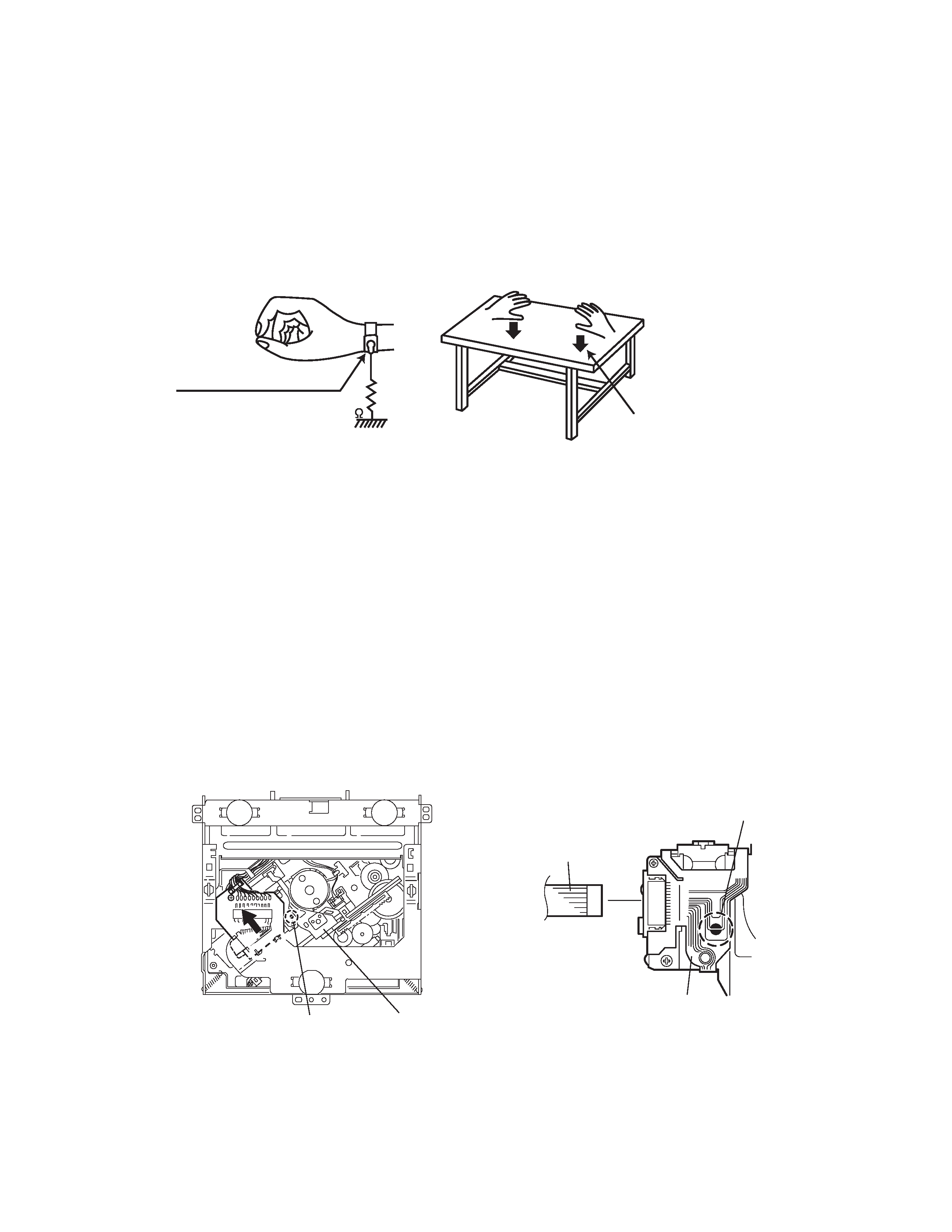
(1) Ground the workbench
Ground the workbench by laying conductive material (such as a conductive sheet) or an iron plate over it before placing the
traverse unit (optical pickup) on it.
(2) Ground yourself
Use an anti-static wrist strap to release any static electricity built up in your body.
(3) Handling the optical pickup
· In order to maintain quality during transport and before installation, both sides of the laser diode on the replacement optical
pickup are shorted. After replacement, return the shorted parts to their original condition.
(Refer to the text.)
· Do not use a tester to check the condition of the laser diode in the optical pickup. The tester's internal power source can easily
destroy the laser diode.
1.3 Handling the traverse unit (optical pickup)
(1) Do not subject the traverse unit (optical pickup) to strong shocks, as it is a sensitive, complex unit.
(2) Cut off the shorted part of the flexible cable using nippers, etc. after replacing the optical pickup. For specific details, refer to the
replacement procedure in the text. Remove the anti-static pin when replacing the traverse unit. Be careful not to take too long a
time when attaching it to the connector.
(3) Handle the flexible cable carefully as it may break when subjected to strong force.
(4) I t is not possible to adjust the semi-fixed resistor that adjusts the laser power. Do not turn it.
1.4 Attention when traverse unit is decomposed
*Please refer to "Disassembly method" in the text for the CD pickup unit.
· Apply solder to the short land before the flexible wire is disconnected from the connector on the CD pickup unit.
(If the flexible wire is disconnected without applying solder, the CDpickup may be destroyed by static electricity.)
· In the assembly, be sure to remove solder from the short land after connecting the flexible wire.
1M
(caption)
Anti-static wrist strap
Conductive material
(conductive sheet) or iron plate
Pickup
Short-circuit point
(Soldering)
Flexible wire
Pickup
Short-circuit point
KD-SX8350
1-4 (No.49782)
SECTION 2
Disassembly method
2.1 Main body
2.1.1
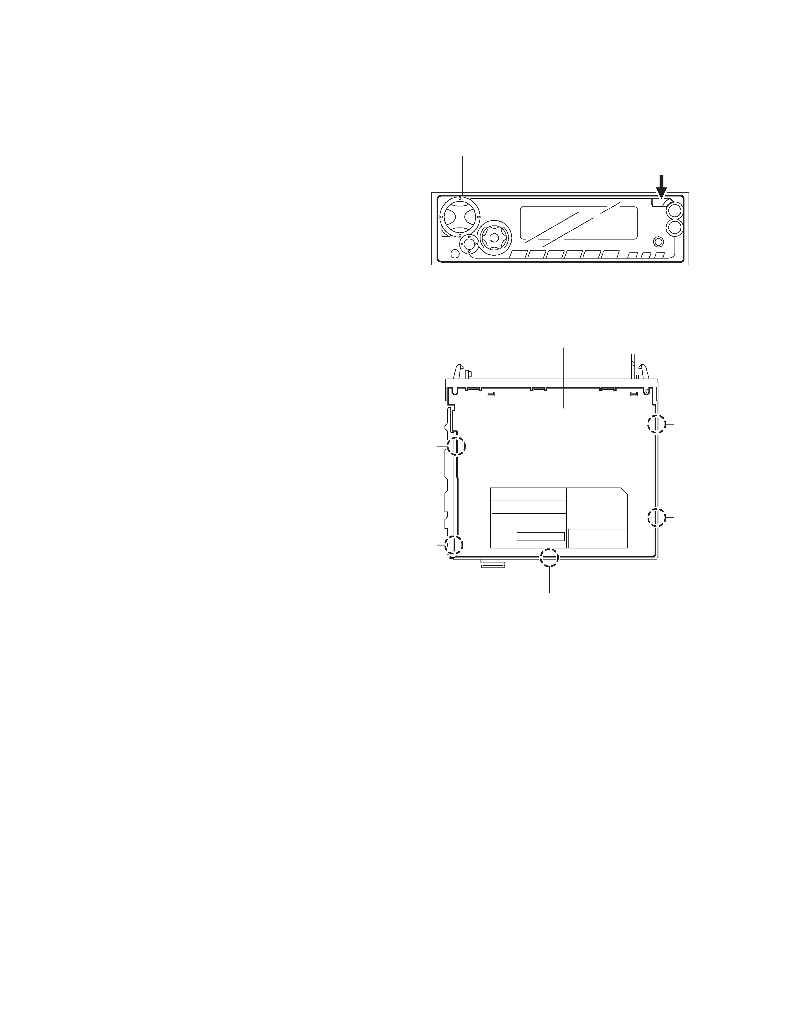
Removing the front panel assembly
(See Fig.1.)
(1) Push the release button and remove the front panel as-
sembly.
Fig.1
2.1.2
Removing the bottom cover
(See fig.2)
(1) Turn over the body and release the two joints a ,the two
joints b and the joint c .
Caution:
Do not damage the board when releasing the joint c us-
ing a screwdriver.
Fig.2
Front panel assembly
Release button
Bottom cover
Joint b
Joint b
Joint c
Joint a
Joint a
KD-SX8350
(No.49782)1-5
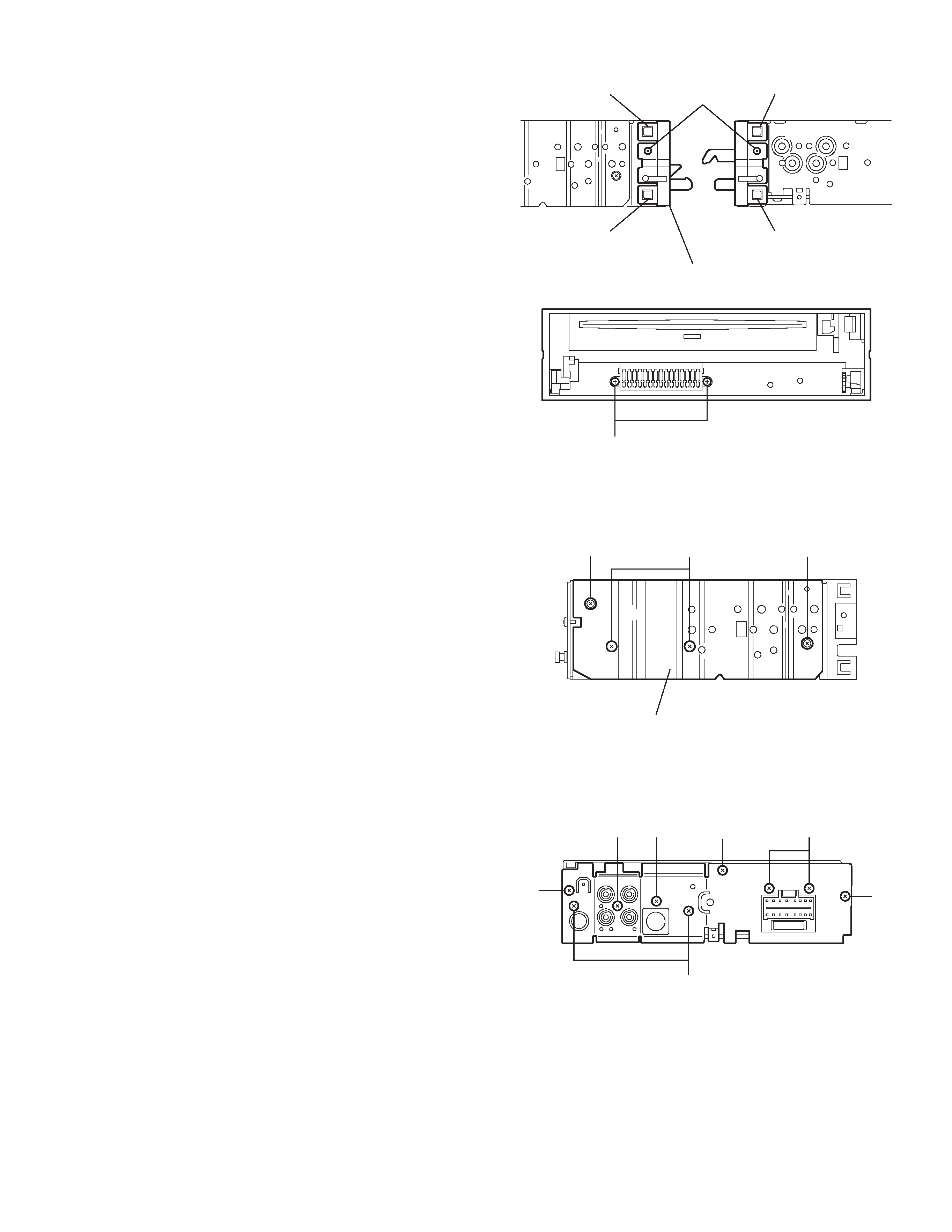
2.1.3 Removing the front chassis assembly
(See fig.3,4)
· Prior to performing the following procedure, remove the front
panel assembly and the bottom cover.
(1) Remove the screws A on the both sides of the body.
(2) Remove the screws B on the front side of the body.
(3) Release the two joints d and the two joints e on the both
sides of the body, using a screwdriver.
Fig.3
Fig.4
2.1.4 Removing the heat sink
(See fig.5)
(1) Remove the two screws C and the two screws D on the left
side oft the body.
Fig.5
2.1.5 Removing the rear panel
(See fig.6)
· Prior to performing the following procedure, remove the front
panel assembly, the front chassis, the heat sink and the bottom
cover.
(1) Remove the three screws E , the three screws F and the
three screws G on the back of the body. Remove the rear
panel.
Fig.6
Joint d
Joint e
Front chassis assembly
Joint d
A
Joint e
B
Heat sink
DC
D
F
F
F
E
E
GG