SERVICE MANUAL
CD RECEIVER
No.49661
Oct. 2001
COPYRIGHT
2001 VICTOR COMPANY OF JAPAN, LTD.
KD-SH99RB
KD-SH99RB
Area Suffix
E
EX
Continental Europe
Central Europe
The addition of the black colour for KD-SH99R.
The content is the same as the silver version before.
Please refer to service manual for KD-SH99R (No.49645) previously
issued when repairing.
1
1
1
1
1
1
1
1
1
1
1
1
1
8
Q'ty
Block No. M1MM
Item
Parts name
Parts number
44
55
79
81
82
83
85
89
90
91
92
96
104
129
GEAR S1
SPACER (F)
FRONT PANEL
AL PANEL
REAR COVER
EARTH SPRING R
PRESET BUTTON
PUSH BUTTON (L)
PUSH BUTTON (R)
D.FUNC BUTTON
DETACH BUTTON
VOL.KNOB ASS'Y
NAME PLATE
PIN CAP
LV42115-003A
LV40846-022A
LV10464-004C
LV32464-015A
LV10465-002A
LV42127-006A
LV20934-003A
LV32557-004A
LV32466-004A
LV20936-006A
LV32467-004A
LV32797-002A
LV33215-001A
GE40101-001A
LV42115-002A
LV40846-015A
LV10464-002A
LV32464-008A
LV10465-001A
LV42127-005A
LV20934-001A
LV32557-001A
LV32466-001A
LV20936-002A
LV32467-002A
LV32797-001A
LV32615-001A
VYTA500-001
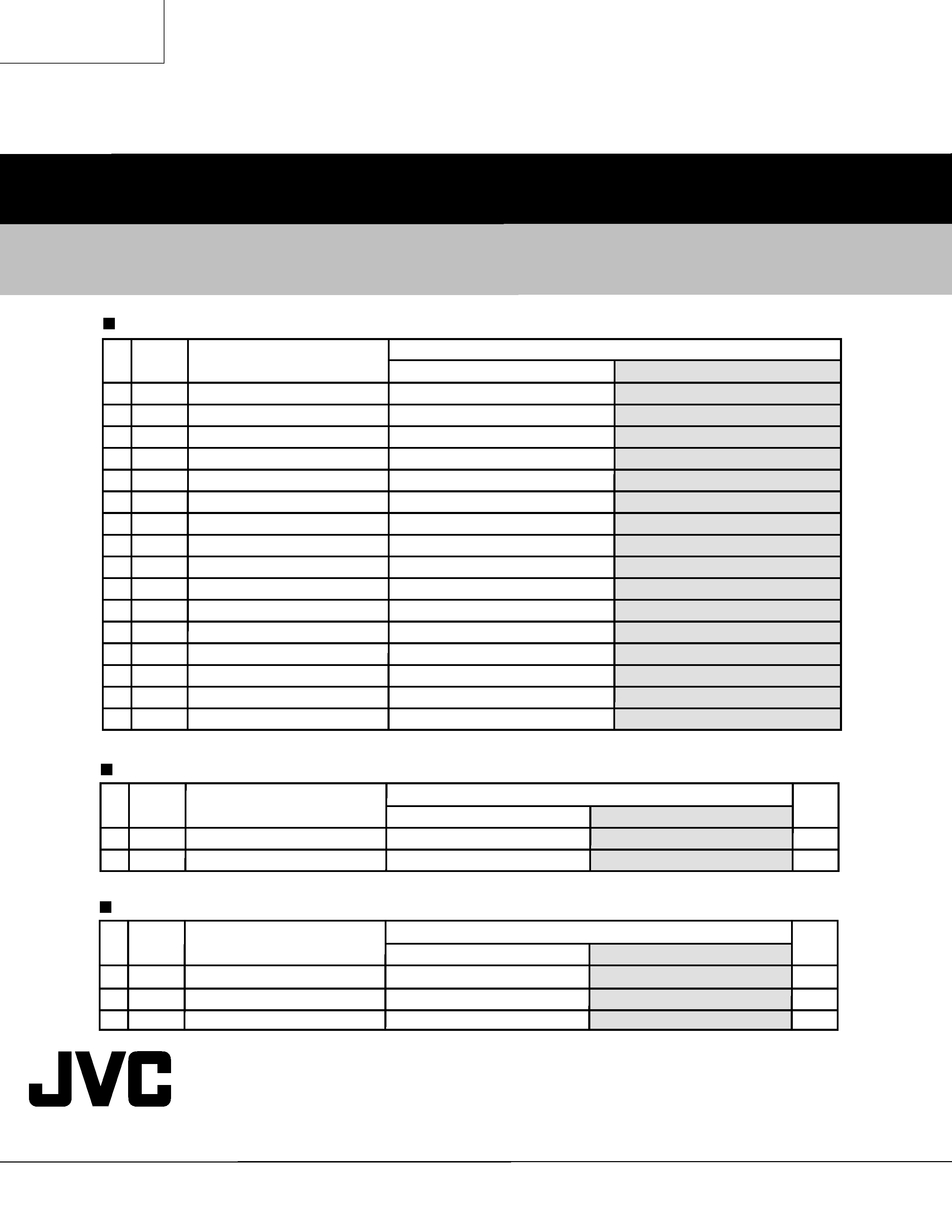
Parts list (General assembly)
A
P3-2
KD-SH99R
KD-SH99RB
Block No. 01
Item
Parts name
Parts number
C175
C323
C982
IC606
R985
E CAPACITOR
E CAPACITOR
E CAPACITOR
IC
MG RESISTOR
---------------------
QERF1AM-107Z
QERF1CM-226Z
UPD703031AGC019
NRAS63J-472X
QERF0JM-476Z
QERF1CM-476Z
QERF1CM-106Z
UPD703031AGC014
NRSA63J-103X
Electrical parts list (Main board)
A
P3-8
KD-SH99R
KD-SH99RB
KD-SH99RB
VICTOR COMPANY OF JAPAN, LIMITED
MOBILE ELECTRONICS DIVISION
PERSONAL & MOBILE NETWORK BUSINESS UNIT. 10-1,1Chome,Ohwatari-machi,Maebashi-city,371-8543,Japan
(No.49661)
200110
Block No. 02
Item
Parts name
Parts number
CN513
R521
R523
R524
R525
R526
R527
R529
R531
R533
R534
R535
R536
R537
R539
R540
ASSY WIRE
MG RESISTOR
MG RESISTOR
MG RESISTOR
MG RESISTOR
MG RESISTOR
MG RESISTOR
MG RESISTOR
MG RESISTOR
MG RESISTOR
MG RESISTOR
MG RESISTOR
MG RESISTOR
MG RESISTOR
MG RESISTOR
MG RESISTOR
WJK0117-001A
NRSA63J-821X
NRSA63J-391X
NRSA63J-391X
NRSA63J-621X
NRSA63J-391X
NRSA63J-391X
NRSA63J-821X
NRSA63J-821X
NRSA63J-391X
NRSA63J-391X
NRSA63J-621X
NRSA63J-391X
NRSA63J-391X
NRSA63J-821X
NRSA63J-821X
WJK0017-001A
NRSA63J-222X
NRSA63J-122X
NRSA63J-122X
NRSA63J-182X
NRSA63J-122X
NRSA63J-122X
NRSA63J-222X
NRSA63J-222X
NRSA63J-122X
NRSA63J-122X
NRSA63J-182X
NRSA63J-122X
NRSA63J-122X
NRSA63J-222X
NRSA63J-332X
Electrical parts list (Front board)
A
P3-14
KD-SH99R
KD-SH99RB
1
1
Q'ty
Block No. M3MM
Item
Parts name
Parts number
P 5
P 6
POLY BAG
CARTON
VPE3005-066
LV33219-001A
VPE3005-064
LV32617-001A
Parts list (Packing)
A
P3-17
KD-SH99R
KD-SH99RB
1
1
1
Q'ty
Block No. M4MM
Item
Parts name
Parts number
A 6
A 15
A 17
TROUBLE SHEET
CAR CABLE
TRIM PLATE
---------------------
QAM0267-001
LV20938-004A
LVT0770-002A
QAM0106-001
LV20938-002A
Parts list (Accessories)
A
P3-17
KD-SH99R
KD-SH99RB
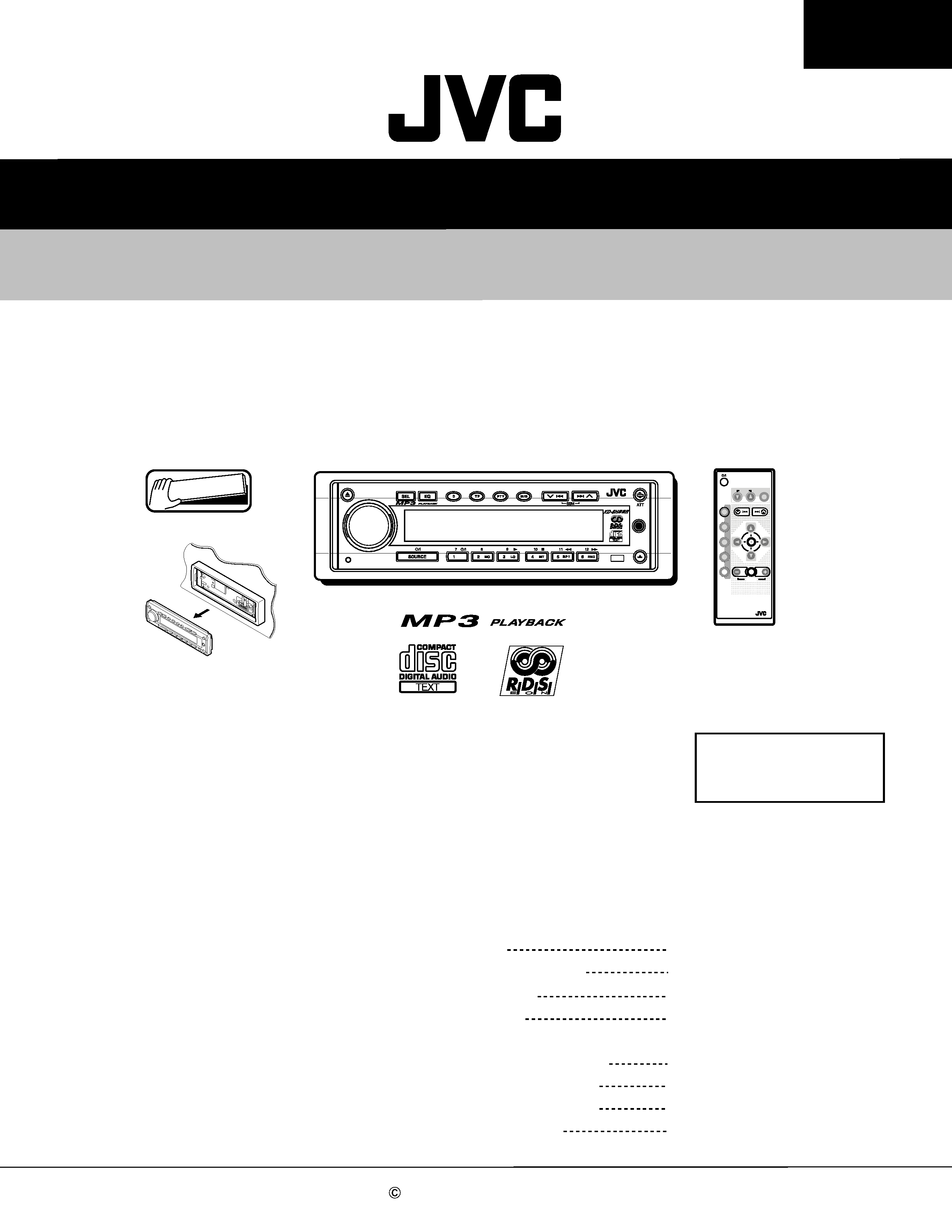
SERVICE MANUAL
CD RECEIVER
No.49645
Jun. 2001
COPYRIGHT
2001 VICTOR COMPANY OF JAPAN, LTD.
KD-SH99R
KD-SH99R
Area Suffix
Contents
Safety precaution
Preventing static electricity
Disassembly method
Adjustment method
Flow unit reading TOC
of CD/CD-R/CD-RW
Maintenance of laser pickup
Replacement of laser pickup
Description of major ICs
1- 2
1- 3
1- 4
1-15
1-18
1-20
1-20
1-21~45
E ------- Continental Europe
EX ----- Central Europe
Detachable
ANGLE
RM-RK100
EQ
CD
FM
AM
CH
AUX
SEL
VOLUME
R D
ATT
MC-Service
KD-SH99R
1-2
!
Burrs formed during molding may be left over on some parts of the chassis. Therefore,
pay attention to such burrs in the case of preforming repair of this system.
Safety precaution
!
Please use enough caution not to see the beam directly or touch it in case of an
adjustment or operation check.
KD-SH99R
1-3
Front bracket
CD mechanism
control board
Damper bracket
CD mechanism ass'y
FD screw
Feed motor ass'y
FD gear
Pickup unit
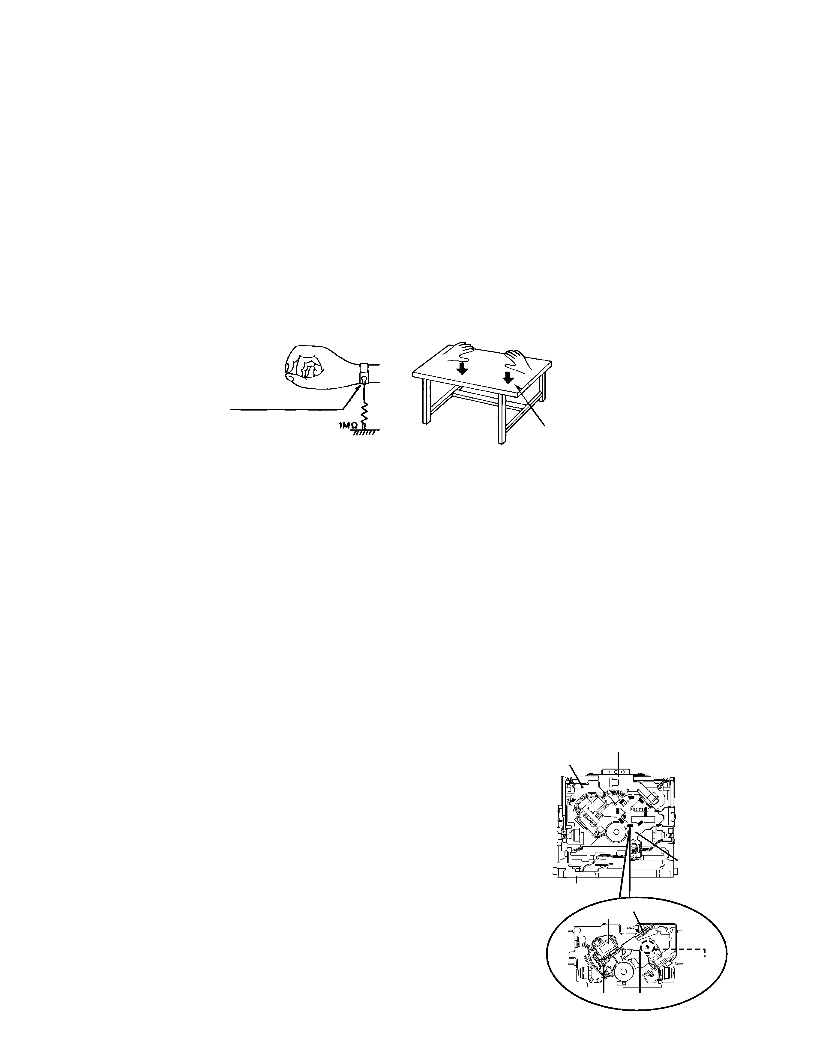
Preventing static electricity
1.Grounding to prevent damage by static electricity
Electrostatic discharge (ESD), which occurs when static electricity stored in the body, fabric, etc. is discharged,
can destroy the laser diode in the traverse unit (optical pickup). Take care to prevent this when performing repairs.
2.About the earth processing for the destruction prevention by static electricity
Static electricity in the work area can destroy the optical pickup (laser diode) in devices such as CD players.
Be careful to use proper grounding in the area where repairs are being performed.
2-1 Ground the workbench
Ground the workbench by laying conductive material (such as a conductive sheet) or an iron plate over
it before placing the traverse unit (optical pickup) on it.
2-2 Ground yourself
Use an anti-static wrist strap to release any static electricity built up in your body.
3. Handling the optical pickup
1. In order to maintain quality during transport and before installation, both sides of the laser diode on the
replacement optical pickup are shorted. After replacement, return the shorted parts to their original condition.
(Refer to the text.)
2. Do not use a tester to check the condition of the laser diode in the optical pickup. The tester's internal power
source can easily destroy the laser diode.
4.Handling the traverse unit (optical pickup)
1. Do not subject the traverse unit (optical pickup) to strong shocks, as it is a sensitive, complex unit.
2. Cut off the shorted part of the flexible cable using nippers, etc. after replacing the optical pickup. For specific
details, refer to the replacement procedure in the text. Remove the anti-static pin when replacing the traverse
unit. Be careful not to take too long a time when attaching it to the connector.
3. Handle the flexible cable carefully as it may break when subjected to strong force.
4. It is not possible to adjust the semi-fixed resistor that adjusts the laser power. Do not turn it
Conductive material
(conductive sheet) or iron plate
(caption)
Anti-static wrist strap
Soldering
Attention when traverse unit is decomposed
1.Solder is put up before the card wire is removed from connector on
the CD substrate as shown in Figure.
(When the wire is removed without putting up solder, the CD pick-up
assembly might destroy.)
2.Please remove solder after connecting the card wire with
when you install picking up in the substrate.
*Please refer to "Disassembly method" in the text for pick-up and how to
detach the substrate.
MC-Service