SERVICE MANUAL
AV SELECTOR
No.70251
Mar. 2001
COPYRIGHT
2001 VICTOR COMPANY OF JAPAN, LTD.
Printed in Japan
0103(S)
VICTOR COMPANY OF JAPAN, LIMITED
COMMUNICATION NETWORK BUSINESS UNIT, 1644, SHIMOTSURUMA, YAMATO-SHI, KANAGAWA-KEN, 242-8514, JAPAN
JX-S555 (J)
No.70251
JX-S555(J)
JX-S555(J)
JX-S555(J)
No.
70251
Contents
Safety Precautions ...............................
2
Main Parts Locations ............................ 3
Disassembly of Parts ............................ 4
Connection Diagram ............................. 6
Circuit Description ................................
7
Adjustments ......................................... 11
Position of ICs and Adjustment Points ....... 12
Servicing Guidelines ............................ 13
Block View Inside IC ............................. 17
Design and specifications are subject to change without notice.
JX-S555(J)
2 (No. 70251)
Safety Precautions
1. This design of this product contains special hardware and many circuits and components specially
for safety purposes.
For continued protection, no changes should be made to the original design
unless authorized in writing by the manufacturer.
Replacement parts must be identical to those
used in the original circuits.
Services should be performed by qualified personnel only.
2. Alterations of the design or circuitry of the product should not be made.
Any design alterations of
the product should not be made.
Any design alterations or additions will
void the manufacturer`s
warranty and will further relieve the manufacture of responsibility for personal injury or property
damage resulting therefrom.
3. Many electrical and mechanical parts in the products have special safety-related characteristics.
These characteristics are often not evident from visual inspection nor can the protection afforded
by them necessarily be obtained by using replacement components rated for higher voltage,
wattage, etc.
Replacement parts which have these special safety characteristics are identified in
the Parts List of Service Manual.
Electrical components having such features are identified by
shading on the schematics and by (
) on the Parts List in the Service Manual.
The use of a
substitute replacement which does not have the same safety characteristics as the recommended
replacement parts shown in the Parts List of Service Manual may create shock, fire, or other
hazards.
4. The leads in the products are routed and dressed with ties, clamps, tubings, barriers and the
like to be separated from live parts, high temperature parts, moving parts and/or sharp edges
for the prevention of electric shock and fire hazard.
When service is required, the original lead
routing and dress should be observed, and it should be confirmed that they have been returned
to normal, after re-assembling.
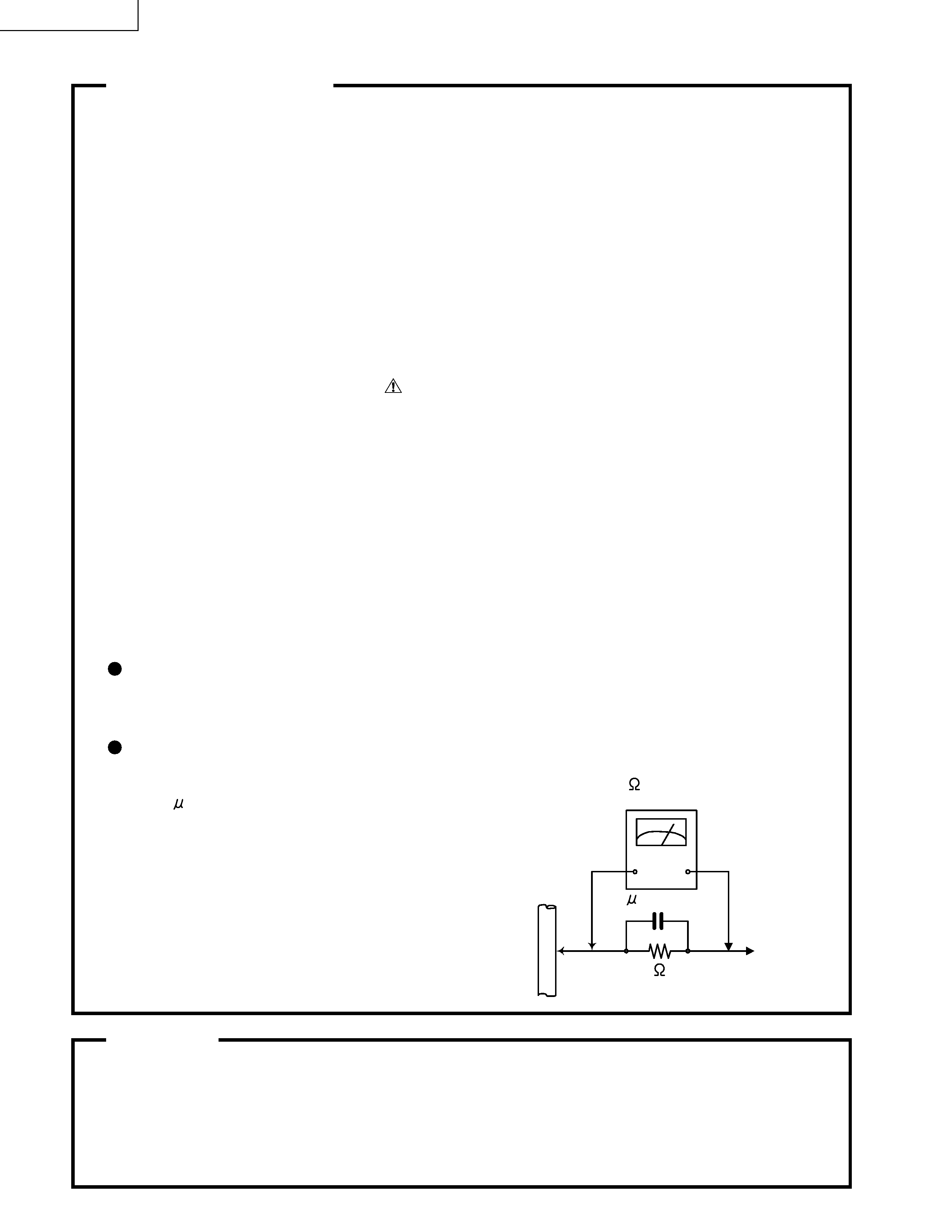
5. Leakage currnet check (Electrical shock hazard testing)
After re-assembling the product, always perform an isolation check on the exposed metal parts
of the product (antenna terminals, knobs, metal cabinet, screw heads, headphone jack, control
shafts, etc.) to be sure the product is safe to operate without danger of electrical shock.
Do not use a line isolation transformer during this check.
Plug the AC line cord directly into the AC outlet.
Using a "Leakage Current Tester", measure
the leakage
current from each exposed metal parts of the cabinet , particularly any exposed
metal part having a return path to the chassis, to a known good earth ground. Any leakage
current must not exceed 0.5mA AC (r.m.s.)
Alternate check method
Plug the AC line cord directly into the AC outlet.
Use an AC voltmeter having, 1,000 ohms
per volt or more sensitivity in the following manner. Connect a 1,500
10W resistor paralleled by
a 0.15 F AC-type capacitor between an exposed
metal part and a known good earth ground.
Measure the AC voltage across the resistor with the
AC voltmeter.
Move the resistor connection to eachexposed metal
part, particularly any exposed metal part having a
return path to the chassis, and meausre the AC
voltage across the resistor. Now, reverse the plug in
the AC outlet and repeat each measurement. voltage
measured Any must not exceed 0.75 V AC (r.m.s.).
This corresponds to 0.5 mA AC (r.m.s.).
Warning
1. This equipment has been designed and manufactured to meet international safety standards.
2. It is the legal responsibility of the repairer to ensure that these safety standards are maintained.
3. Repairs must be made in accordance with the relevant safety standards.
4. It is essential that safety critical components are replaced by approved parts.
5. If mains voltage selector is provided, check setting for local voltage.
Good earth ground
Place this
probe on
each exposed
metal part.
AC VOLTMETER
(Having 1000
ohms/volts,
or more sensitivity)
1500
10W
0.15 F AC TYPE
(No. 70251) 3
JX-S555(J)
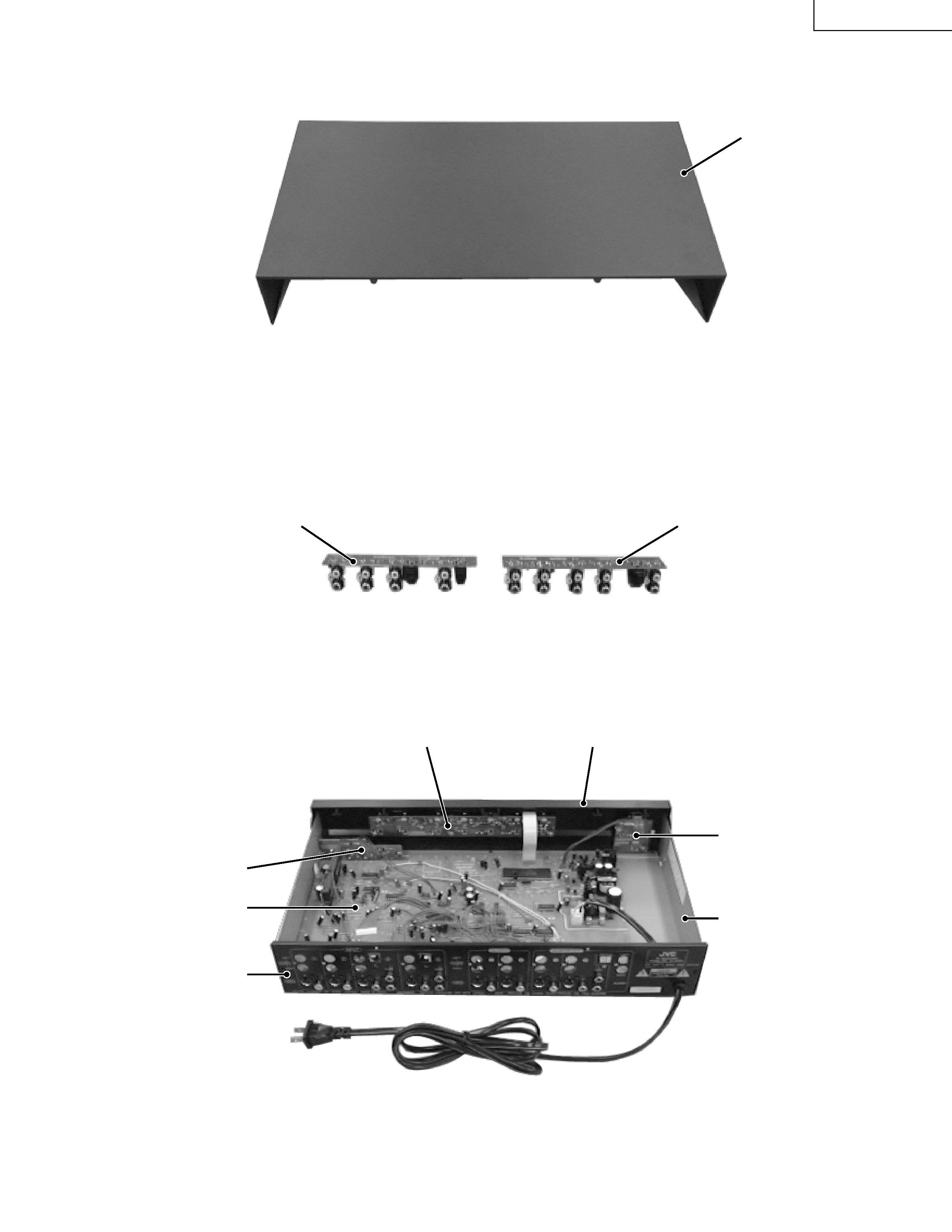
Main Parts Locations
AUDIO 2 board
AUDIO 1 board
Front 1 board
Bottom chassis
Front panel ass'y
Front 2 board
Rear panel
MAIN board
Jack board
Top cover
JX-S555(J)
4 (No. 70251)
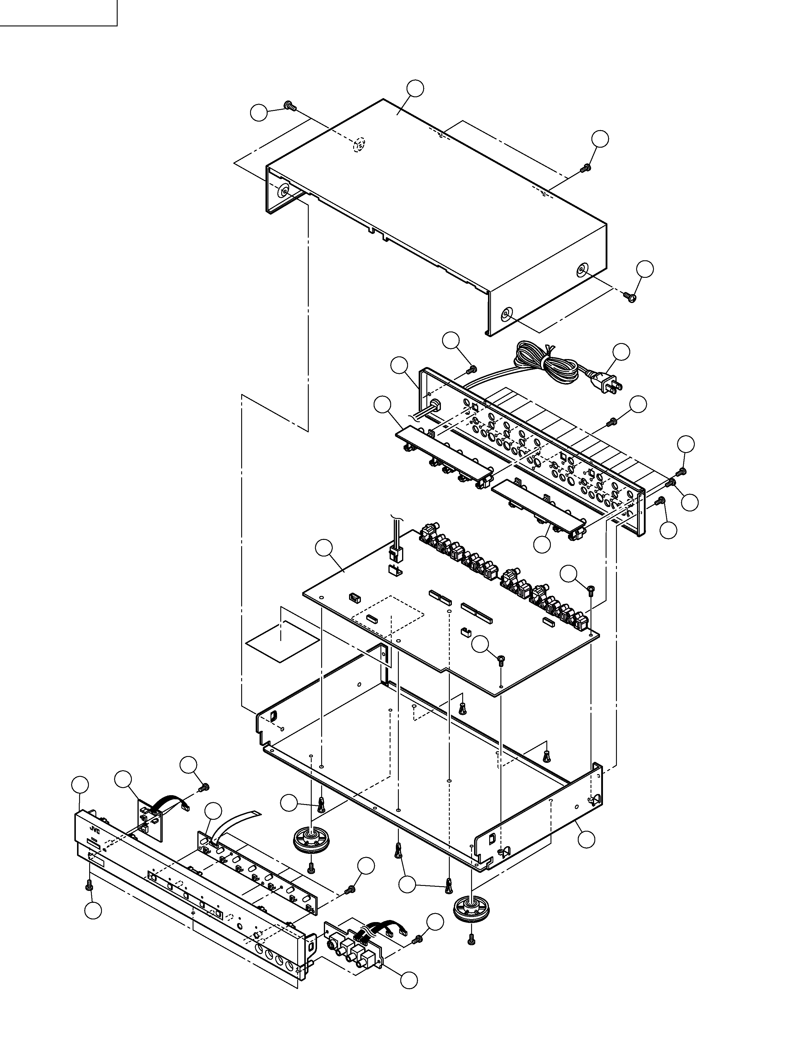
Disassembly of Parts
2
17
6
11
18
17
17
5
14
14
16
22
9
8
15
21
22
20
13
19
12
7
4
3
4
1
15
(No. 70251) 5
JX-S555(J)
Note : For the positions of the connectors, see the connection
diagram (page 6).
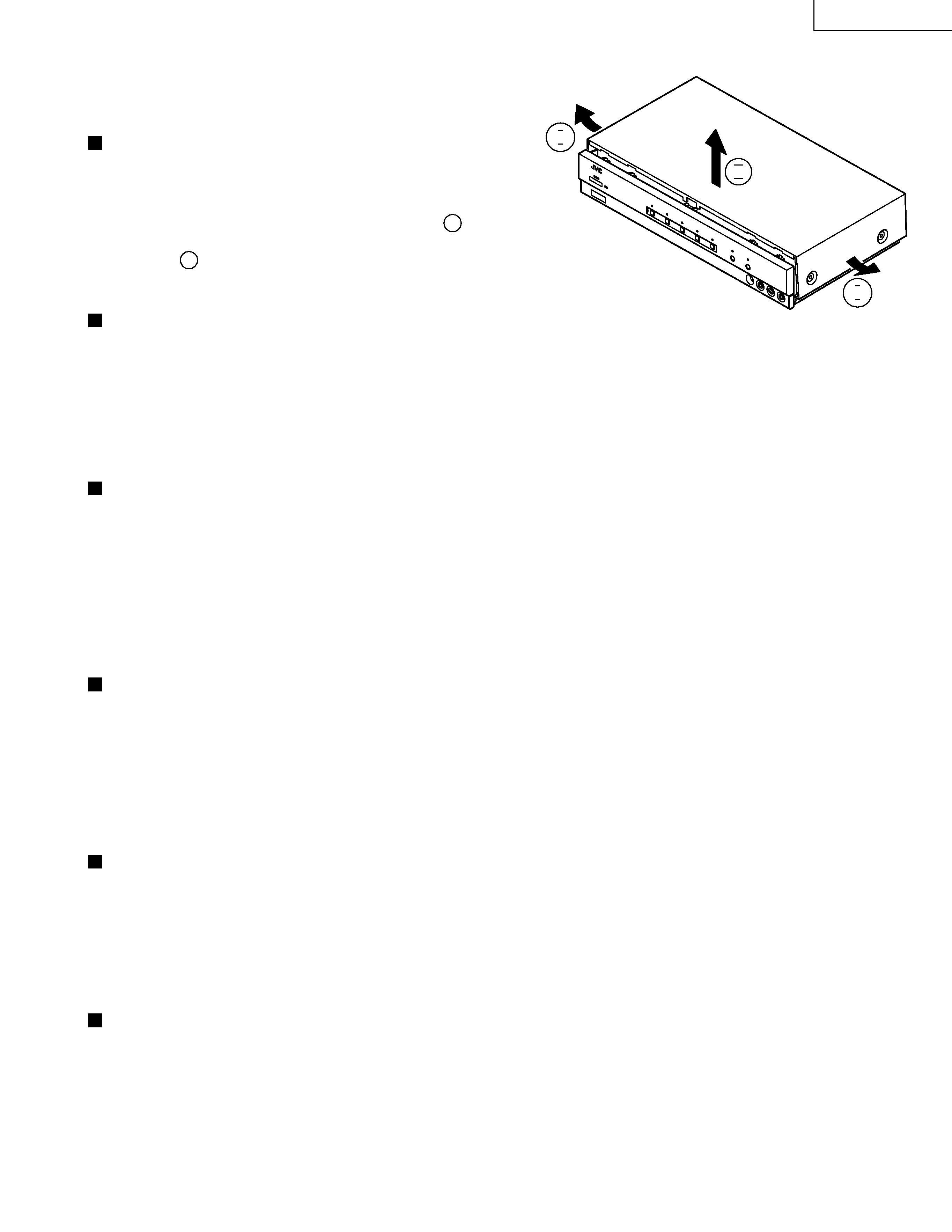
Removing the top cover
1
1
1
1
1
1. Remove the two screws 3 retaining the top cover 1 from the
rear panel 2, then remove the four screws 4 retaining the
top cover from the side panels.
2. Slightly open out the bottoms of the side skirts
I of the top
cover 1 as shown in the figure, then pull the top cover straight
upward
II . Do not remove the top cover by pulling it up in an
oblique direction.
Removing the Audio 1 Board
5
5
5
5
5 and Audio 2
Board
6
6
6
6
6
1. Remove the top cover 1.
2. From the rear panel 2, remove the six screws 7 retaining the Audio 1 board 5 and the six screws 7 retaining the
Audio 2 board 6.
3. Gently remove the Audio 1 board 5 and then unplug the connectors CN809 and CN810 from it.
4. Gently remove the Audio 2 board 6 and then unplug the connectors CN807 and CN808 from it.
Removing the Main Board
B
B
B
B
B
1. Remove the top cover 1, then the Audio 1 board 5 and finally the Audio 2 board 6.
2. From the rear panel 2, remove the nineteen screws C retaining the Main board B.
3. Unplug the connectors CN1, CN3, CN804 and CN811 (and the wire from the Front Panel Assembly D )on the Main
board B .
4. Unplug the connector CN901 (in the power supply circuit) on the Main board B.
5. Remove the two clamping screws E on the Main board B.
6. Disengage the three claws of the locking card spacer F on the Main board B, then remove the Main board by lifting
it in an oblique direction.
Removing the Rear Panel
2
2
2
2
2
1. Remove the top cover 1.
2. Unplug the connector CN901 (in the power supply circuit) on the Main board B.
3. Remove the twelve screws 7 retaining the Audio 1 board 5 and the Audio 2 board 6, then remove the nineteen screws
CretainingtheMainboardB.
4. Remove the three screws H retaining the bottom chassis G and the rear panel 2.
5. Gently remove the rear panel 2.
(Take care of the AC power cord I connected to the rear panel 2.)
Removing the Front Panel Assembly
D
D
D
D
D
1. Remove the top cover 1.
2. Remove the three retaining screws J from the bottom of the Front Panel Assembly D.
3. Disengage the fittings between the side panels of the Front Panel Assembly D with the bottom chassis G, then
gently pull out the Front Panel Assembly D from the bottom chassis G toward the front.
4. Unplug the connectors CN1, CN3, CN804 and CN811 from the Main board B.
5. Remove the Front Panel Assembly D.
Removing the Front 1 Board
K
K
K
K
K, Front 2 Board L
L
L
L
L and Jack Board 8
8
8
8
8
1. Remove the top cover 1 and the Front Panel Assembly D.
2. Remove the two screws M retaining the Front 1 board K, five screws M retaining the Front 2 board L and the two screws
9 retaining the Jack board 8.
3. Remove the Front 1 board K, the Front 2 board L and the Jack board 8.
II
I
I