IF-C42P1G
INSTRUCTIONS
VIDEO INPUT UNIT
BEDIENUNGSANLEITUNG
:VIDEOEINGANGSEINHEIT
MANUEL D'INSTRUCTIONS
:MODULE D'ENTRÉE VIDÉO
MANUALE DI ISTRUZIONI
:UNITÀ D'INGRESSO VIDEO PERTANTO
INSTRUCCIONES
:UNIDAD DE ENTRADA DE VIDEO
:
LCT1429-001A
ENGLISH
DEUTSCH
FRANÇAIS
ITALIANO
ESPAÑOL
VIDEO INPUT UNIT FOR A JVC PLASMA DISPLAY MONITOR
VIDEOEINGANGSEINHEIT FÜR EIN JVC PLASMAMONITOR
MODULE D'ENTRÉE VIDÉO POUR UN MONITEUR DE
VISUALISATION PLASMA
UNITÀ D'INGRESSO VIDEO PERTANTO UN MONITOR DE AL
PLASMA
UNIDAD DE ENTRADA DE VIDEO PARA UN MONITOR
PLASMA DISPLAY
IF-C42P1Gcover_Cs65
4/21/03, 11:15 AM
Page 3
Adobe PageMaker 6.5C/PPC
2
AC IN
AUDIO
L
OUT
R
RGB A
AUDIO
IN
REMOTE
RS-232C
WIRED
MAKE
AUDIO
L
OUT
R
REMOTE
RS-232C
WIRED
MAKE
RGB A
AUDIO
IN
This Video Input unit allows the Plasma Display Monitor GM-V42PCE, GM-V42PCEG and GM-V42PCEB to cope with video signals
-- Video (composite), S-video(Y/C), and Component/RGB -- and audio signals.
SAFETY PRECAUTIONS
· This installation requires technical skills and electrical acknowledgment. It is very dangerous to install this kit by yourself.
For installation, consult JVC authorized dealer.
· Some of the parts, such as rear panel and blank panel, are very heavy and have keen edges. Be careful when handling them.
Preparation
Tools:
Plus (+) screwdriver
Work table: Prepare a table with a flat surface 105 cm x 65 cm or wider, and place a suitable cushion or soft cloth on it.
INSTALLATION
1 Turn off the power of the Plasma Display
Monitor and then disconnet the power
cord.
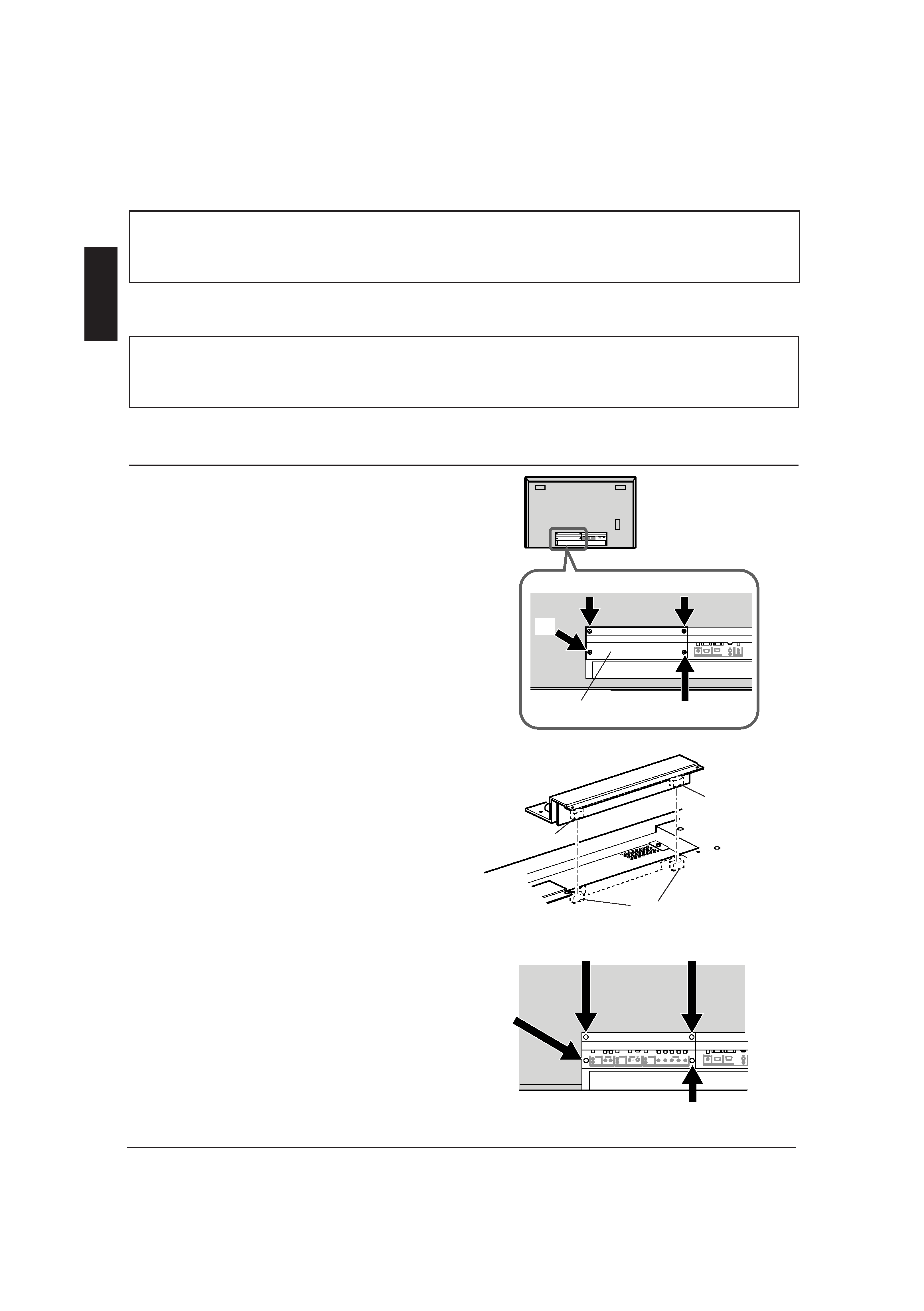
2 Remove the blank panel of the Plasma
Display Monitor.
1) Place the Plasma Display Monitor upside down
(with the screen faced downward) on the work
table gently.
Note:
Be careful not to get the screen glass scratched or
damaged.
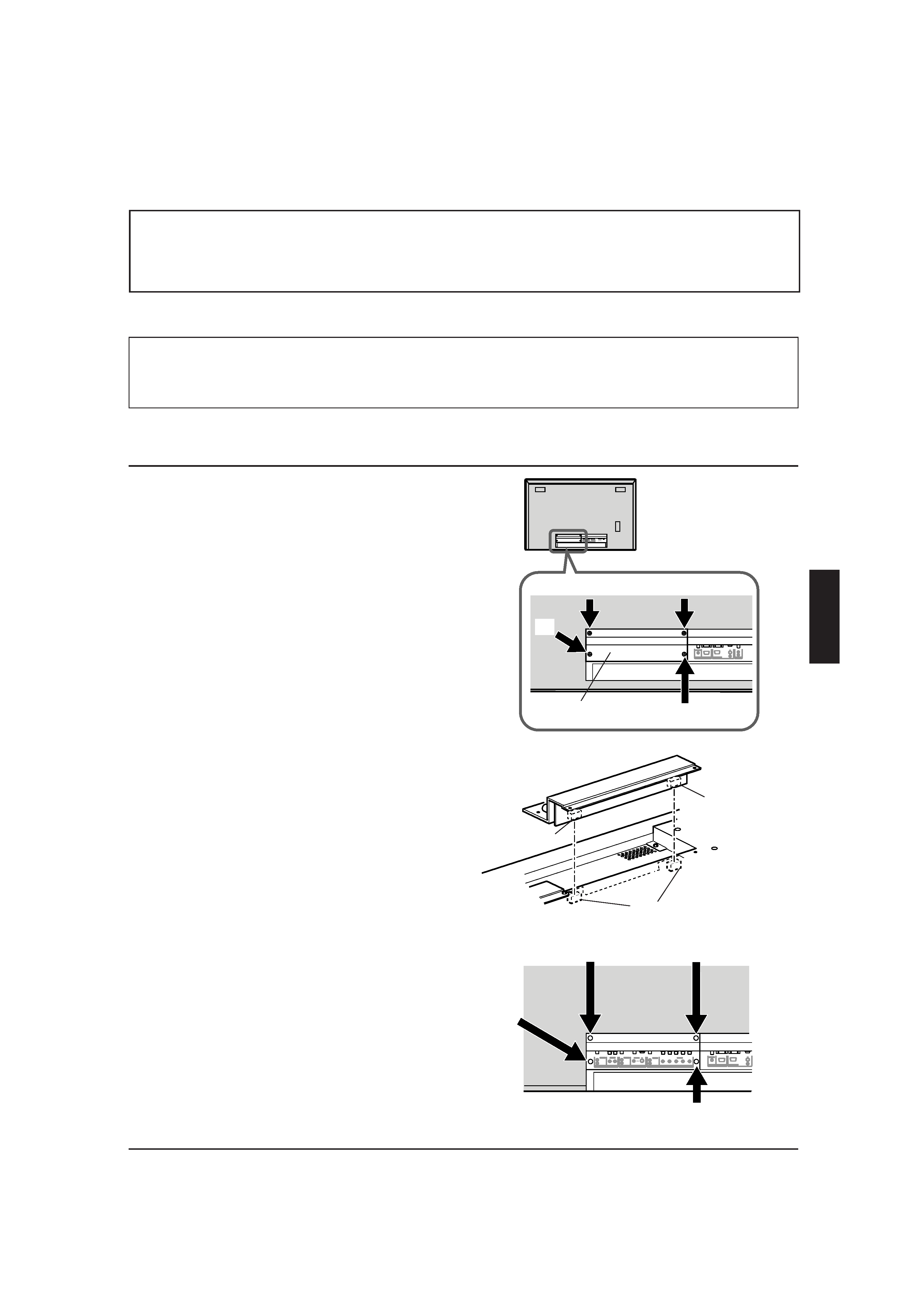
2) Unscrew the 4 screws (1 to 4) indicated in the
illustration (Fig. 1) to detach the blank panel of
the Plasma Display Monitor.
Note:
This removed blank panel is not used when printed
board ass'y is installed. Retain all the screws for later
use.
3 Install the Video Input Unit.
1) There are two connectors on the inner surface of
the Video Input Unit.
By aligning these two connectors with the
connectors inside the monitor, push the Video
Input Unit so that the connectors are fully
connected.
2) Fix the Video Input Unit with the 4 screws
removed in step 2 (1 to 4) (Fig. 3).
4 Operate the Plasma Display Monitor.
After the Video Input Unit is installed, operate the
monitor and check that image and sound are
reproduced correctly through the following inputs:
VIDEO A, VIDEO B, and COMPONENT/RGB
terminals.
3
1
4
2
Fig. 3
Fig. 1
Fig. 2
Rear cover
Connector
Connector
Connector
Video Input Unit
Blank panel
3
1
4
2
Rear side
ENGLISH
RGB A
AUDIO
IN
REMOTE
RS-232C
WIRED
MAKE
VIDEO A
VIDEO
IN
OUT
AUDIO
L/MONO
R
VIDEO B
VIDEO
IN
Y/C IN
COMPONENT/RGB B
VIDEO
Y/G
Pb/B
Pr/R
HD/Cs
VD
AUDIO
L/MONO
R
AUDIO
L/MONO
R
IF_C42P1G.p65
03.4.24, 2:51 PM
2
3
AC IN
AUDIO
L
OUT
R
RGB A
AUDIO
IN
REMOTE
RS-232C
WIRED
MAKE
AUDIO
L
OUT
R
REMOTE
RS-232C
WIRED
MAKE
RGB A
AUDIO
IN
Mithilfe dieser Videoeingangseinheit werden die Plasmamonitoren GM-V42PCE, GM-V42PCEG und GM-V42PCEB so erweitert,
dass sie Videosignale FBAS-Signale, S-Videosignale (Y/C) und Komponenten-/RGB-Signale und Audiosignale erkennen.
SICHERHEITSMASSNAHMEN
· Diese Installation erfordert technische Fertigkeiten und elektrotechnische Kenntnisse. Es ist sehr gefährlich, diese Einheit selbst zu
installieren.Beauftragen Sie einen autorisierten JVC-Fachhändler mit der Installation.
· EinigeTeile,z.B.dieRückwandunddieBlindplatte,sindsehrschwerundhabenscharfeKanten.GehenSievorsichtigmitihnen um..
Vorbereitung
Werkzeuge: Kreuzschlitzschraubendreher
Arbeitstisch: Bereiten Sie einen Tisch mit einer ebenen Fläche von mindestens 105 cm x 65 cm vor, und bedecken Sie ihn
mit einem geeigneten Kissen oder weichen Tuch.
INSTALLATION
1 Schalten Sie den Plasmamonitor aus, und
trennen Sie ihn anschließend vom Netz.
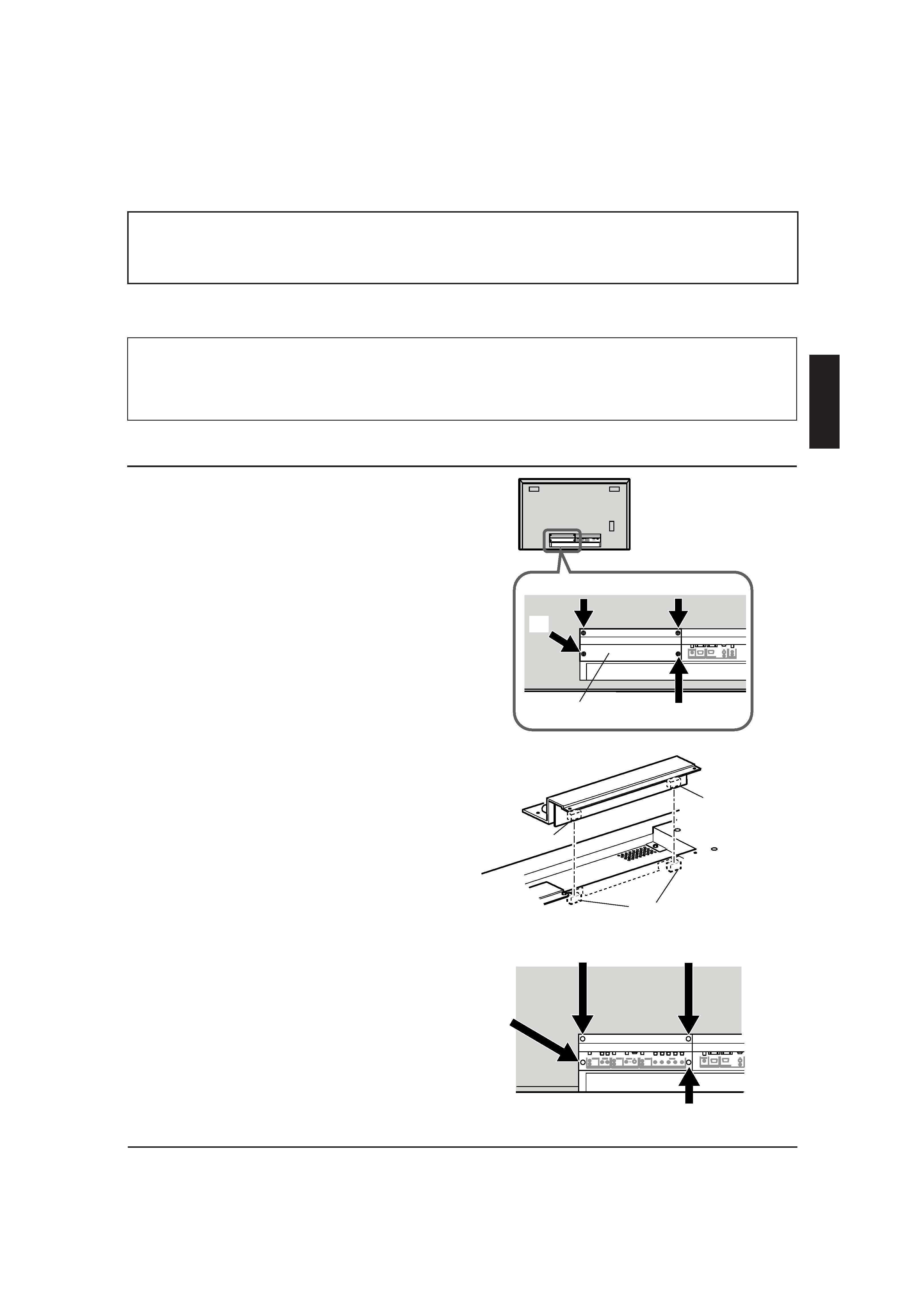
2 Bauen Sie die Blindplatte des
Plasmamonitors aus.
1) Legen Sie den Plasmamonitor vorsichtig auf den
Tisch, so dass der Bildschirm nach unten weist.
Hinweis:
Gehen Sie sehr vorsichtig vor, um zu verhindern, dass
das Glas des Bildschirms zerkratzt oder anderweitig
beschädigt wird.
2) Drehen Sie die 4 Schrauben (1 bis 4) heraus, die
in der Abbildung (Abb.1) gekennzeichnet sind,
um die Blindplatte aus dem Plasmamonitor
herausnehmen zu können.
Hinweis:
Diese Blindplatte wird nicht benötigt, wenn andere
gedruckte Schaltungen installiert werden. Heben Sie
alle Schrauben zur späteren Verwendung auf.
3 Installieren Sie die Videoeingangseinheit.
1) Auf der Innenseite der Videoeingangseinheit sind
zwei Anschlüsse vorgesehen.
Richten Sie diese beiden Anschlüsse auf die
entsprechenden Anschlüsse im Monitor aus, drücken
Sie die Videoeingangseinheit auf diese Anschlüsse, so
dass sie fest miteinander verbunden sind.
2) Befestigen Sie die Videoeingangseinheit mit den 4
Schrauben, die Sie in Schritt 2 herausgedreht
haben (1 bis 4) (Abb. 3).
4 Schalten Sie den Plasmamonitor ein.
Nachdem Sie die Videoeingangseinheit installiert haben,
schalten Sie den Monitor ein, und überprüfen Sie, ob Bild
und Ton über die folgenden Eingänge ordnungsgemäß
wiedergegeben werden:
Eingänge VIDEO A, VIDEO B und COMPONENT/RGB.
3
14
2
Abb. 3
Abb. 1
Abb. 2
Hintere
Abdeckung
Anschluss
Anschluss
Videoeingangseinheit
Blindplatte
3
1
4
2
Rückseite
Anschluss
DEUTSCH
RGB A
AUDIO
IN
REMOTE
RS-232C
WIRED
MAKE
VIDEO A
VIDEO
IN
OUT
AUDIO
L/MONO
R
VIDEO B
VIDEO
IN
Y/C IN
COMPONENT/RGB B
VIDEO
Y/G
Pb/B
Pr/R
HD/Cs
VD
AUDIO
L/MONO
R
AUDIO
L/MONO
R
IF_C42P1G.p65
03.4.24, 2:51 PM
3
4
RGB A
AUDIO
IN
REMOTE
RS-232C
WIRED
MAKE
VIDEO A
VIDEO
IN
OUT
AUDIO
L/MONO
R
VIDEO B
VIDEO
IN
Y/C IN
COMPONENT/RGB B
VIDEO
Y/G
Pb/B
Pr/R
HD/Cs
VD
AUDIO
L/MONO
R
AUDIO
L/MONO
R
AC IN
AUDIO
L
OUT
R
RGB A
AUDIO
IN
REMOTE
RS-232C
WIRED
MAKE
AUDIO
L
OUT
R
REMOTE
RS-232C
WIRED
MAKE
RGB A
AUDIO
IN
Outils:
Tournevis cruciforme (+)
Plan de travail: Préparez une table avec une surface plate de 105 cm x 65 cm ou plus large, et placez un coussin ou un tissu
doux sur celle-ci.
PRÉCAUTIONS DE SÉCURITÉ
· Cette installation nécessite des connaissances techniques et en électricité. Il est très dangereux d'installer ce module vous-même.
Pour l'installation, consultez votre revendeur JVC autorisé.
· Certaines pièces, telles que le panneau arrière et le panneau vide, sont très lourdes et ont des bords coupants. Faites attention lors de leur
manipulation.
Ce module d'entrée vidéo permet au moniteur de visualisation plasma GM-V42PCE, GM-V42PCEG et GM-V42PCEB de recevoir
les signaux vidéo -- Vidéo (composite), S-vidéo (Y/C) et Composantes/RVB -- et les signaux audio.
Préparations
INSTALLATION
1 Mettez le moniteur de visualisation
plasma hors tension et déconnectez le
cordon d'alimentation.
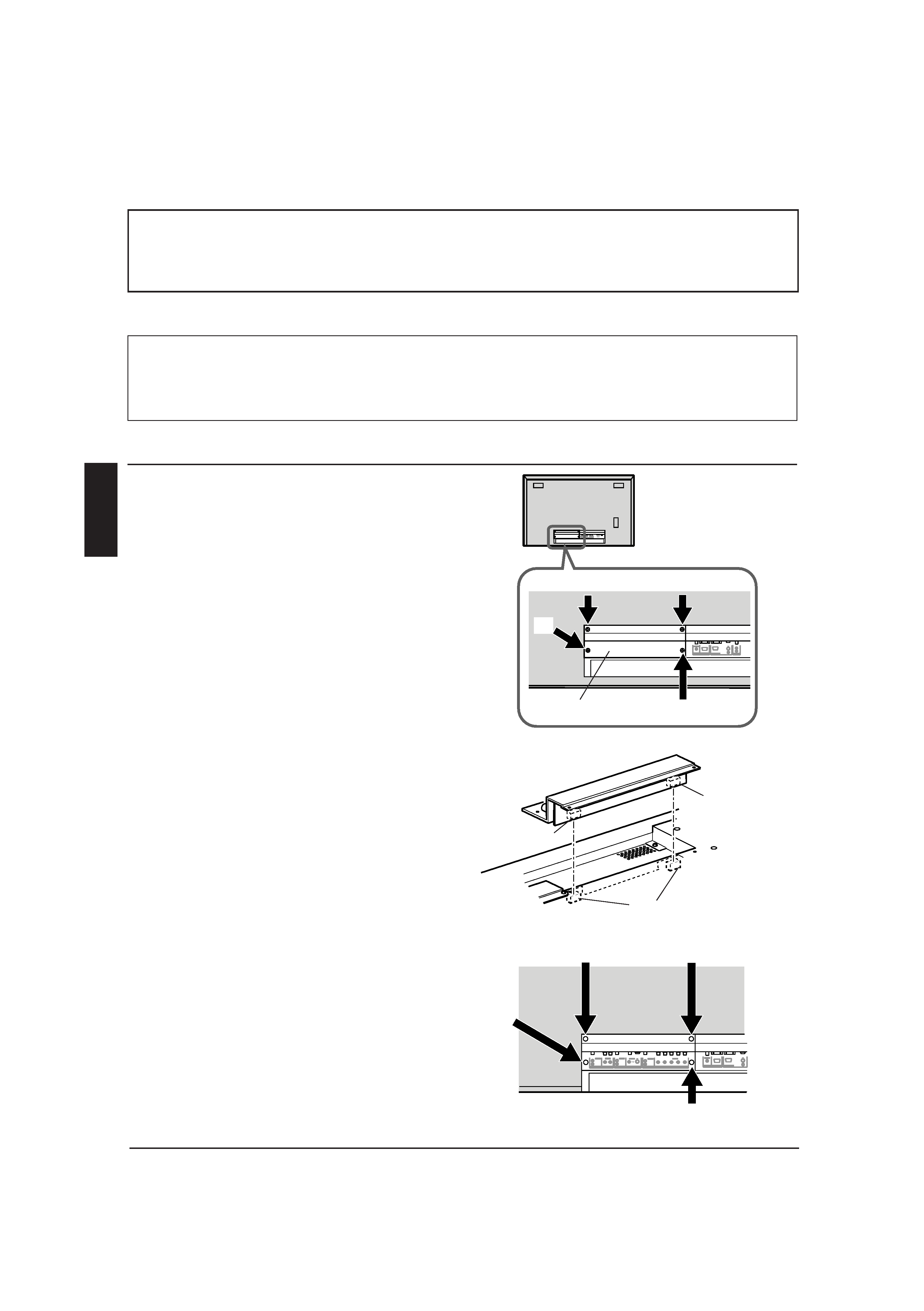
2 Retirez le panneau vide du moniteur de
visualisation plasma.
1) Placez délicatement le moniteur de visualisation
plasma à l'envers (avec l'écran dirigé vers le bas)
sur le plan de travail.
Remarque:
Faites attention de ne pas rayer ou endommager la
vitre de l'écran.
2) Dévissez les 4 vis (1 à 4) indiquées sur
l'illustration (Fig. 1) pour détacher le panneau
vide du moniteur de visualisation plasma
Remarque:
Le panneau vide retiré n'est pas utilisé quand
l'ensemble du circuit imprimé est installé. Conservez
toutes les vis pour une utilisation future.
3 Installez le module d'entrée vidéo.
1) Il y a deux connecteurs sur la surface intérieure
du module d'entrée vidéo.
Alignez ces deux connecteurs avec les
connecteurs du moniteur et poussez le module
d'entrée vidéo de façon que les connecteurs soient
connectés à fond.
2) Fixez le module d'entrée vidéo avec les 4 vis
retirées à l'étape 2 (1 à 4) (Fig. 3).
4 Utilisez le moniteur de visualisation
plasma.
Après avoir installé le module d'entrée vidéo, faites
fonctionner le moniteur et vérifiez que l'image et le
son sont reproduits correctement à travers les prises
d'entrées suivantes: VIDEO A, VIDEO B et COMPO-
NENT/RGB.
3
14
2
Fig. 3
Fig. 1
Fig. 2
Panneau
arrière
Connecteur
Connecteur
Connecteur
Module d'entrée
vidéo
Panneau
vide
3
1
4
2
Face arrière
FRANÇAIS
IF_C42P1G.p65
03.4.24, 2:51 PM
4
5
AC IN
AUDIO
L
OUT
R
RGB A
AUDIO
IN
REMOTE
RS-232C
WIRED
MAKE
AUDIO
L
OUT
R
REMOTE
RS-232C
WIRED
MAKE
RGB A
AUDIO
IN
3
PRECAUZIONI DI SICUREZZA
· Questo tipo d'installazione richiede competenze tecniche e conoscenze in campo elettrico. Pertanto è estremamente pericoloso
installare il kit direttamente.Per l'installazione, rivolgersi al rivenditore JVC autorizzato.
· Alcuni componenti, come il pannello posteriore e il coperchio, sono molto pesanti e presentano angoli vivi. Si consiglia di maneggiarli
con la massima attenzione.
L'unità d'ingresso video consente al monitor al plasma GM-V42PCE, GM-V42PCEG e GM-V42PCEB di ricevere i segnali video --
Video (composito), S-video(Y/C) e Component/RGB -- e segnali audio.
Operazioni preliminari
Attrezzi:
Acciavite a croce
Work table: Prepare a table with a flat surface 105 cm x 65 cm or wider, and place a suitable cushion or soft cloth on it.
INSTALLAZIONE
1 Spegnere il monitor al plasma e
scollegare il cavo di alimentazione.
2 Togliere il coperchio del monitor al
plasma.
1) Posizionare delicatamente il monitor al plasma
capovolto (schermo verso il basso) sul tavolo di
lavoro.
Nota:
Fare attenzione a non graffiare o rovinare il vetro dello
schermo.
2) Svitare le 4 viti (da 1 a 4 ) indicate in figura
(Fig.1) per staccare il coperchio del monitor al
plasma.
Nota:
Il coperchio non deve essere utilizzato se si installa una
scheda aggiuntiva. Conservare le viti per uso futuro.
3 Installare l'unità d'ingresso video.
1) Sulla superficie interna dell'unità video sono
presenti due connettori.
Allineando questi due connettori con quelli
all'interno del monitor, spingere l'unità d'ingresso
video in modo che i connettori risultino
perfettamente collegati.
2) Fissare l'unità d'ingresso video con le 4 viti tolte
al punto 2 (da 1 a 4 )(Fig.3).
4 Attivare il monitor al plasma.
Dopo l'installazione dell'unità d'ingresso video,
attivare il monitor e verificare che suono e immagine
vengano riprodotti correttamente attraverso i
seguenti ingressi:
Terminali VIDEO A, VIDEO B e COMPONENT/RGB.
14
2
Fig. 3
Fig. 1
Fig. 2
Coperchio
posteriore
Connettore
Connettore
Connettore
Unità d'ingresso
video
Coperchio
3
1
4
2
Pannello posteriore
ITALIANO
RGB A
AUDIO
IN
REMOTE
RS-232C
WIRED
MAKE
VIDEO A
VIDEO
IN
OUT
AUDIO
L/MONO
R
VIDEO B
VIDEO
IN
Y/C IN
COMPONENT/RGB B
VIDEO
Y/G
Pb/B
Pr/R
HD/Cs
VD
AUDIO
L/MONO
R
AUDIO
L/MONO
R
IF_C42P1G.p65
03.4.24, 2:51 PM
5