
OPERATING INSTRUCTIONS
IF-C422P1G Video Input Unit
IF-C422P1G videoeingangseinheit
IF-C422P1G module d'entrée vidéo
IF-C422P1G unità d'ingresso video
IF-C422P1G unidad de entrada de video
IF-C422P1G
VIDEO INPUT UNIT FOR A JVC PLASMA DISPLAY MONITOR
VIDEOEINGANGSEINHEIT FÜR EIN JVC PLASMAMONITOR
MODULE D'ENTRÉEVIDÉO POUR UN MONITEUR DE VISUALISATION PLASMA
UNITÀ D'INGRESSO VIDEO PERTANTO UN MONITOR DE AL PLASMA
UNIDAD DE ENTRADA DE VIDEO PARA UN MONITOR PLASMA DISPLAY
INSTALLATION MANAUL
INSTALLATIONANLEITUNG
MANUEL D'INSTRUCTIONS
MANUALE D'INSTALLAZIONE
MANUAL DE INSTALACION
LCT1151-001A
ENGLISH
DEUTSCH
FRANÇAIS
ITALIANO
ESPAÑOL
2
This Video Input unit allows the Plasma Display Monitor GM-P420PCE and GM-P421PCE to cope with video signals -- Video
(composite), S-video(Y/C), and Component/RGB -- and audio signals.
SAFETY PRECAUTIONS
· This installation requires technical skills and electrical acknowledgment. It is very dangerous to install this kit by yourself.
For installation, consult JVC authorized dealer.
· Some of the parts, such as rear panel and blank panel, are very heavy and have keen edges. Be careful when handling them.
Preparation
Tools:
Plus (+) screwdriver
Work table: Prepare a table with a flat surface 105 cm x 65 cm or wider, and place a suitable cushion or soft cloth on it.
INSTALLATION
1 Turn off the power of the Plasma Display
Monitor and then disconnet the power
cord.
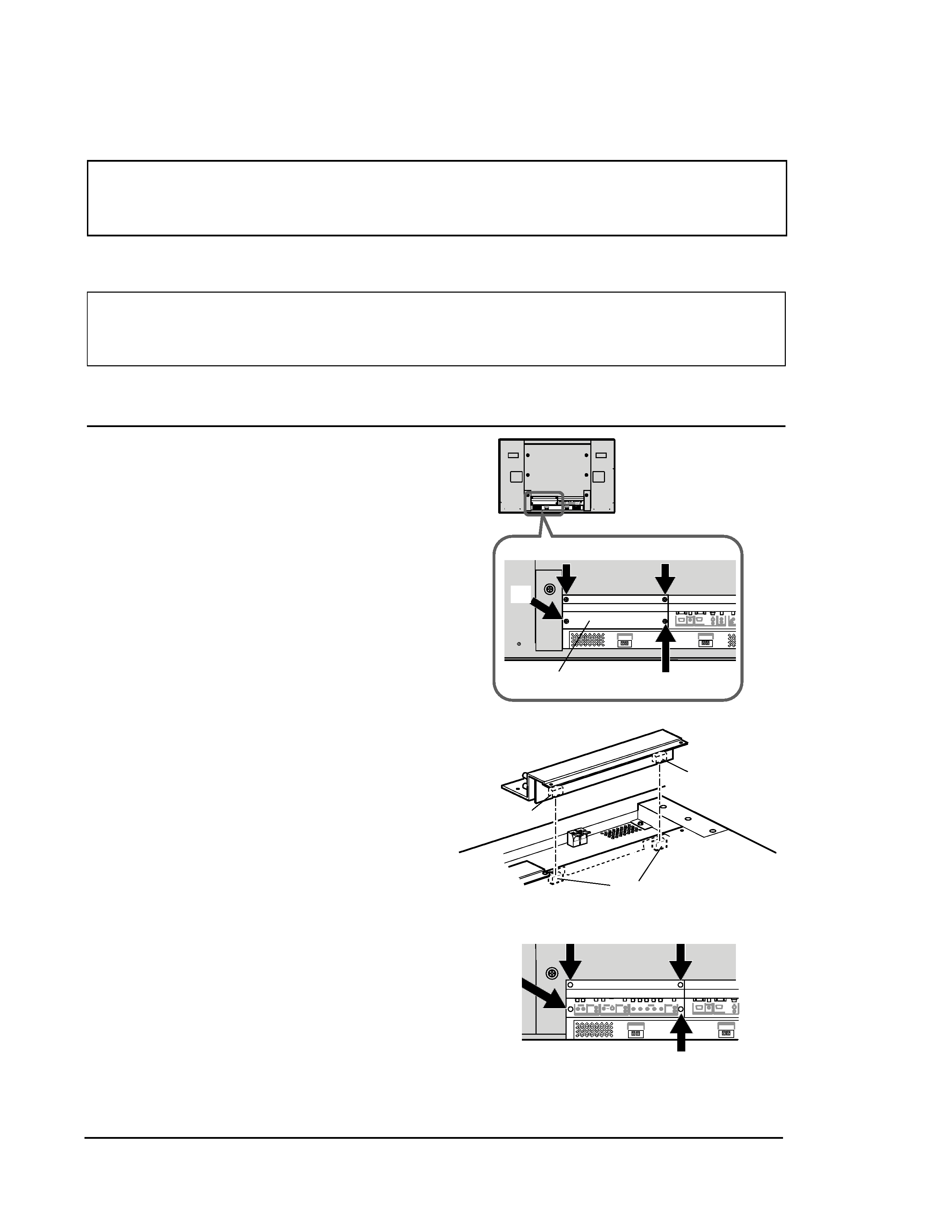
2 Remove the blank panel of the Plasma
Display Monitor.
1) Place the Plasma Display Monitor upside down
(with the screen faced downward) on the work
table gently.
Note:
Be careful not to get the screen glass scratched or
damaged.
2) Unscrew the 4 screws (
1 to 4) indicated in the
illustration (Fig. 1) to detach the blank panel of
the Plasma Display Monitor.
Note:
This removed blank panel is not used when printed
board ass'y is installed. Retain all the screws for later
use.
3 Install the Video Input Unit.
1) There are two connectors on the inner surface of
the Video Input Unit.
By aligning these two connectors with the
connectors inside the monitor, push the Video
Input Unit so that the connectors are fully
connected.
2) Fix the Video Input Unit with the 4 screws
removed in step 2 (
1 to 4) (Fig. 3).
4 Operate the Plasma Display Monitor.
After the Video Input Unit is installed, operate the
monitor and check that image and sound are
reproduced correctly through the following inputs:
VIDEO A, VIDEO B, and COMPONENT/RGB
terminals.
RGB A
AUDIO
IN
REMOTE
RS-232C
WIRED
MAKE
SPEAKER OUT
9
(
L
SPEAKER OUT
9
(
R
VIDEO A
AUDIO
VIDEO
IN
OUT
L/MONO
R
VIDEO B
AUDIO
VIDEO
IN
Y/C IN
L/MONO
R
COMPONENT/RGB B
AUDIO
VIDEO
Y/G
Pb/B
Pr/R
HD/Cs
VD
L/MONO
R
3
1
4
2
Fig. 3
Fig. 1
Fig. 2
Rear cover
Connector
Connector
Connector
Video Input Unit
POWER
AC IN
OPTION
AUDIO
L
OUT
R
RGB A
AUDIO
IN
REMOTE
RS-232C
WIRED
MAKE
SPEAKER OUT
9
(
L
SPEAKER OUT
9
(
R
OPTION
AUDIO
L
OUT
R
RGB A
AUDIO
IN
REMOTE
RS-232C
WIRED
MAKE
SPEAKER OUT
9
(
L
SPEAKER OUT
9
(
R
Blank panel
3
1
4
2
Rear side
ENGLISH