ENGLISH
DEUTSCH
FRANÇAIS
ITALIANO
ESPAÑOL
MULTI-FORMAT SDI UNIT
IF-C151HDG
MULTI-FORMAT SDI UNIT FOR A JVC MONITOR
BEDIENUNGSANLEITUNG
: MULTI-SYSTEM SDI-GERÄT
MANUEL D'INSTRUCTIONS
: UNITÉ SDI MULTI-FORMAT
ISTRUZIONI
: UNITÀ SDI MULTI-FORMATO
MANUAL DE INSTRUCCIONES : UNIDAD SDI MULTIFORMATO
:
UNIDAD SDI MULTIFORMATO PARA MONITOR JVC
UNITÀ SDI MULTI-FORMATO PER MONITOR JVC
UNITÉ SDI MULTI-FORMAT POUR MONITEUR JVC
MULTI-SYSTEM SDI-GERÄT FÜR EINEN JVC-MONITOR
LCT1878-001A
INSTRUCTIONS
LCT1878-001A_Cover.p65
05.5.20, 3:33 PM
3
1
ENGLISH
IF-C151HDG is only for use with the monitor specified. Consult your dealer about the
monitor which can be used with IF-C151HDG.
Features
· Both HD SDI and SD SDI signals can be input through one terminal.
The signal type (HD SDI or SD SDI) coming through the terminal is automatically detected.
· Two input lines enables highly general use.
Input lines can be switched by external control--make contact control, trigger pulse control, and RS-
485 control.
· AUDIO LEVEL METER enables checking the audio level of the EMBEDDED AUDIO signal input.
· Two channels of audio monitor output enables EMBEDDED AUDIO signal to be output as analogue
signal.
Output channels can be switched by using the monitor or an RS-485 control.
Thank you for purchasing this JVC Multi-Format SDI Unit. In order to take full
advantage of the unit's capabilities, please read and follow all instructions carefully
before installing and using the unit. Retain this booklet for future reference.
Precautions
Before installing this unit in your monitor, please read the Safety
Precautions included in your monitor's user manual.
FCC NOTICE (U.S.A. only)
CAUTION: Changes or modifications not approved by JVC could void the user's authority to
operate the equipment.
NOTE: This equipment has been tested and found to comply with the limits for a Class A digital
device, pursuant to Part 15 of the FCC Rules. These limits are designed to provide reasonable
protection against harmful interference when the equipment is operated in a commercial
environment. This equipment generates, uses, and can radiate radio frequency energy and, if not
installed and used in accordance with the instruction manual, may cause harmful interference to
radio communications. Operation of this equipment in a residential area is likely to cause harmful
interference in which case the user will be required to correct the interference at his own expense.
EMC Supplement (Europe only)
This equipment is in conformity with the provisions and protection requirements of the
corresponding European Directives. This equipment is designed for professional video appliances
and can be used in the following environments:
· Controlled EMC environment (for example purpose built broadcasting or recording studio), and
the rural outdoors environment (far away from railways, transmitters, overhead power lines, etc.)
Accessaries
Make sure that the following items are contained:
· Input unit (x 1)
· Cover (x 1)
· Wire connector (x 1)
· Screw (x 8)
EN_LCT1878-001A.p65
05.5.2, 7:43 PM
1
2
7 Preparation
· Wear gloves to protect your hands from metal parts on the unit.
· You will need a 6 mm Phillips screwdriver.
· Turn off the Monitor's main power and unplug the power cable from the AC outlet.
7 Cautions
· Do not touch the wires or board pattern inside of the unit to keep them from being damaged.
· Do not put any object into the unit from the holes on the unit.
· Do not force to tighten the screws when attaching the unit to the monitor.
· Keep the connector cover attached to the monitor's connector if the unit is not attached to the monitor.
· Do not touch the connector on the right side of the unit. This connector is used only for servicing.
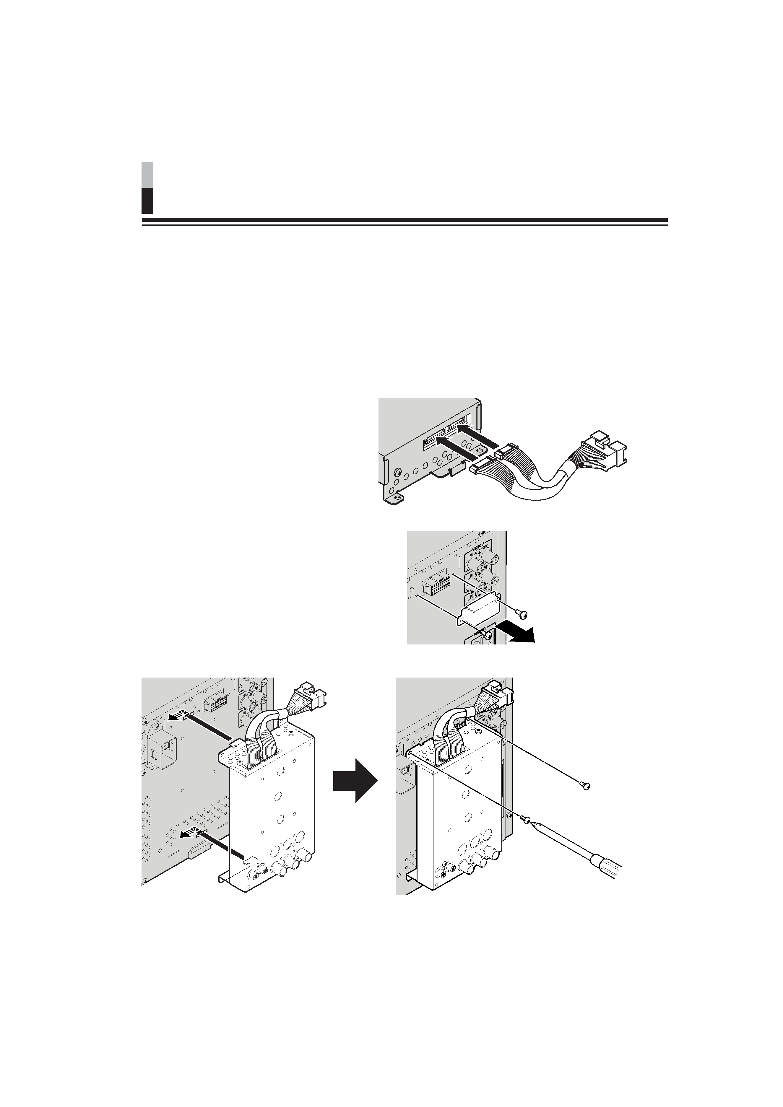
1. Attach the wire connector to the
connector on the input unit.
Attach the wire connector fully to the
input unit's connector.
2. Take out the screws and remove the
connector cover from the monitor.
· Do not take out other screws than the
ones used for the connector cover.
· Keep the connector cover and the
screws after removing.
3. Attach the input unit to the monitor as illustrated.
Installation
Secure the input unit using
the supplied screws (x 2).
EN_LCT1878-001A.p65
05.5.2, 7:43 PM
2
3
ENGLISH
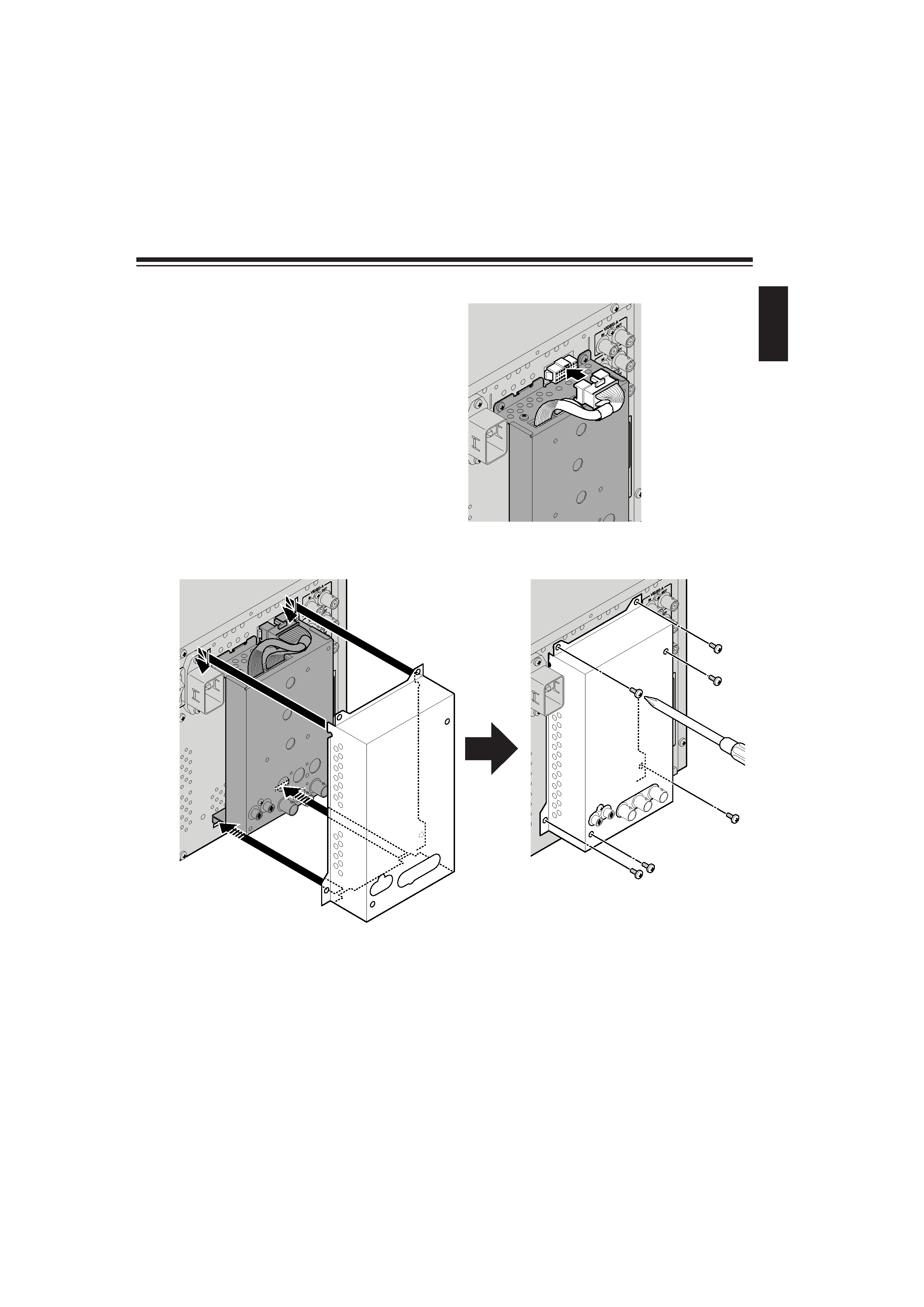
4. Attach the wire connector to the
connector on the monitor.
Attach the wire connector fully to the
monitor's connector.
5. Attach the cover to the monitor as illustrated.
Secure the cover using
the supplied screws (x 6).
Make sure to prevent the wire
from being caught in between
the cover and the monitor.
EN_LCT1878-001A.p65
05.5.2, 7:43 PM
3
4
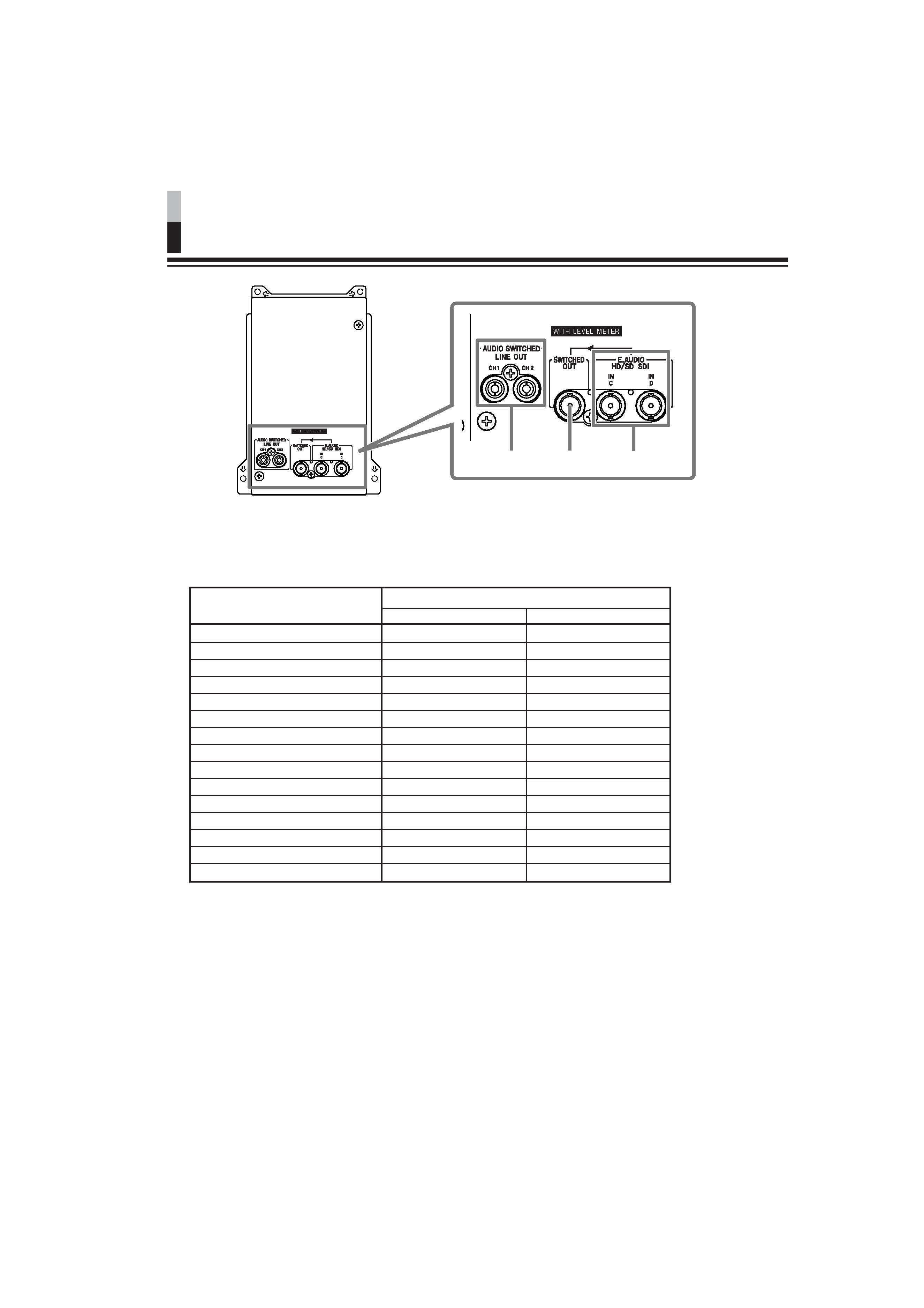
Controls and Features
12
3
1 Audio output terminals (2 lines)
Decodes EMBEDDED AUDIO signals and outputs them as analogue signals.
\ See the table below for the combinations of the audio channels output from the CH1 or CH2
terminal.
* The AUTO setting mixes and outputs all 8 signal channels. The output level is automatically set by
detecting the number of channels the signal has.
Audio output modes
1ch
2ch
3ch
4ch
5ch
6ch
7ch
8ch
12ch
34ch
56ch
78ch
14ch
58ch
AUTO*
CH1
channel 1
channel 2
channel 3
channel 4
channel 5
channel 6
channel 7
channel 8
channels 1+2
channels 3+4
channels 5+6
channels 7+8
channels 14
channels 58
channels 18
CH2
channel 2
channel 2
channel 4
channel 4
channel 6
channel 6
channel 8
channel 8
channels 1+2
channels 3+4
channels 5+6
channels 7+8
channels 14
channels 58
channels 18
Audio output terminals
About the audio output level
When several audio channels are output at the same time, the more channels are
selected, the lower each channel's level will be. (Each channel's level becomes half for 1
2ch, quarter for 14ch.)
NOTES:
· When you change the monitor's input to INPUT A or B, the audio signals and channels of INPUT C
or D selected last time are output from these terminals.
· The audio signal is output from these terminals only when the monitor is turned on.
EN_LCT1878-001A.p65
05.5.2, 7:43 PM
4