INSTRUCTIONS
IF-C01COMG Component/RGB Input Card
IF-C01PNG Video Input Card
IF-C01SDG SDI Input Card
IF-C21SDG
IF-C51SDG
IF-C12HSDG
IF-C21HSDG
IF-C51HSDG
INPUT CARD FOR A JVC MONITOR
BEDIENUNGSANLEITUNG : EINGANGSKARTE FÜR JVC MONITORE
MANUEL D'INSTRUCTIONS : CARTE D'ENTRÉE POUR MONITEURS JVC
MANUALE DI ISTRUZIONI : SCHEDA DI INGRESSO PER MONITOR JVC
INSTRUCCIONES
: TARJETA DE ENTRADA PARA UN
MONITOR JVC
!"
W gs`
!"#$
LCT1409-001A
ENGLISH
DEUTSCH
FRAN
Ç
AIS
ITALIANO
ESPA
Ñ
OL
R
SDI Input Card
(Embedded Audio compatible, Auto Input function compatible)
HD SDI Input Card
(Embedded Audio compatible, Auto Input function
compatible, Audio Level Meter compatible)
SDI Input Card
(Embedded Audio compatible, Auto Input function compatible,
Audio Level Meter compatible)
HD SDI Input Card
(Embedded Audio compatible)
HD SDI Input Card
(Embedded Audio compatible, Auto Input function
compatible)
00_Cover1_SC
17/4/03, 5:21 PM
Page 1
Adobe PageMaker 6.5C/PPC

00_Cover1_SC
17/4/03, 5:21 PM
Page 2
Adobe PageMaker 6.5C/PPC
ENGLISH
1
Before installing this Input Card in your monitor, please read the Safety
Precautions included in your monitor's user manual.
This product is designed exclusively for professional use. Only qualified
technicians or individuals with the appropriate technical knowledge should
perform installation.
FCC NOTICE (U.S.A. only)
CAUTION: Changes or modifications not approved by JVC could void the user's authority to
operate the equipment.
NOTE: This equipment has been tested and found to comply with the limits for a Class A digital
device, pursuant to Part 15 of the FCC Rules. These limits are designed to provide reasonable
protection against harmful interference when the equipment is operated in a commercial
environment. This equipment generates, uses, and can radiate radio frequency energy and, if not
installed and used in accordance with the instruction manual, may cause harmful interference to
radio communications. Operation of this equipment in a residential area is likely to cause harmful
interference in which case the user will be required to correct the interference at his own expense.
Thank you for purchasing this JVC Input Card. In order to take full advantage of the
card's capabilities, please read and follow all instructions carefully before install-
ing and using the card. Retain this booklet for future reference.
EMC Supplement (Europe only)
This equipment is in conformity with the provisions and protection requirements of the corresponding
European Directives. This equipment is designed for professional video appliances and can be used
in the following environments:
Controlled EMC environment (for example purpose built broadcasting or recording studio), and
the rural outdoors environment (far away from railways, transmitters, overhead power lines, etc.)
01_EN
03/4/21, 21:24
1
2
INSTALLATION
The same installation procedure applies to all Input Cards.
If the Input Card is installed correctly, your Monitor will automatically recognise it.
Refer to the user manual provided with your Multi-Format Monitor or Color Video Monitor
for details on adjustment or setting of input signals via the Input Card.
PREPARATION
When using the IF-C21SDG, IF-C51SDG, IF-C21HSDG, or IF-C51HSDG:
Depending upon the monitor in which the card is inserted, it may be necessary to set the DIP switches
on the Input Card. See page 7 "DIP SWITCHES" for details.
· Wear gloves to protect your hands from metal parts on the Input Card's board.
· You will need a 6 mm Phillips screwdriver.
· Turn off the Monitor's main power and unplug the power cable from the AC outlet.
CAUTIONS
· Do not touch the terminal connected to the monitor or board pattern. (Doing so may produce static
electricity that will damage the Input Card.)
· Do not remove slot covers from the monitor's slots if they are not in use.
· Do not force the Input Card into the monitor's slot.
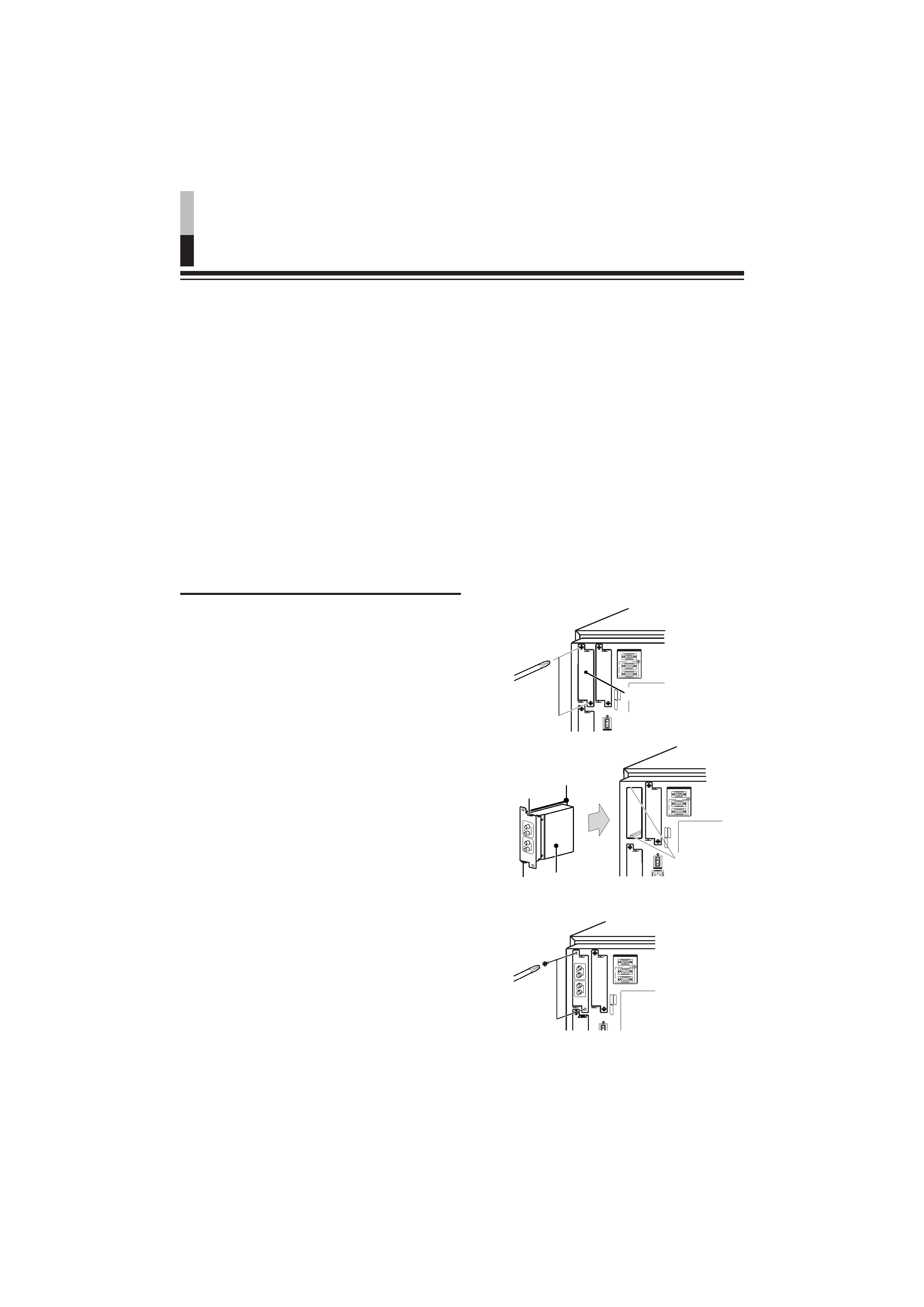
INSTALLATION PROCEDURE
1. Unscrew the screws and remove
the slot cover from the slot (on the
rear side of the monitor) in which
the card is to be installed.
2. Insert the Input Card board (green)
into the slot, fitting the board into
the guide rails at the top and
bottom of the slot.
3. Push the Input Card in so that its
front panel touches the rear panel
of the monitor. (Insert the Input
Card while holding the knobs at
top and bottom).
4. Secure the Input Card by replacing
the screws removed in Step 1 above.
Make sure the Input Card is correctly
installed by checking "SLOT CONDITION"
on the Main Menu of the Multi-format
Monitor. (Also refer to the Multi-format
Monitor instruction manual.)
Press the INPUT SELECT button on the
color video monitor to make sure that the
Input Card is correctly installed. (Also refer to
the Color Video Monitor instruction manual.)
SLO
T
1
SLO
T
3
SLO
T
2
MAKE/TRIGGER
REMOTE
RS-485
IN
OUT
SLO
T1
SLO
T3
SLO
T2
MAKE/TRIGGER
REMOTE
RS-485
IN
OUT
SLO
T1
SLO
T
3
SLO
T2
MAKE/TRIGGER
REMOTE
RS-485
IN
OUT
Slot cover
Rear side of multi-format
monitor
Fit board to
guide rails
Knob
Input Card
(illustration shows
the IF-C12HSDG)
Guide rails
Knob
01_EN
03/4/21, 21:24
2
ENGLISH
3
IF-C01SDG: SDI INPUT CARD
Type
: TM-H Series and DT-V Series monitors
Inputs/Outputs
: Image input: Digital input (SDI 1/SDI 2): 2 lines, BNC connector x 2
(0.8 Vp-p, 75
)
Digital output (SWITCHED OUT): 1 line, BNC connector x 1
(0.8 Vp-p, 75
)
Audio signal: 2 lines (monaural), RCA pin x 4 (0.5 V(rms),
high impedance)
* The input (IN) and output (OUT) terminals are bridge-connected.
Format
: D1 serial component digital, 525/625 auto switching (compliant to
SMPTE259M)
Required slots
:1
Power consumption : 7 V DC, 0.65 A
Weight
: 0.5 k
g
Dimensions
(W x H x D)
: 43 mm x 154.5 mm x 191.9 mm
IF-C01PNG: VIDEO INPUT CARD
Type
: DT-V Series monitors
Inputs/Outputs
: Image input: VIDEO 1/VIDEO 2: 2 lines, BNC connector x 4
(1 Vp-p, 75
)
* NTSC and PAL compatible.
Synchronised signal (EXT.SYNC): 1 line, BNC connector x 2
(0.3 V 4.0 Vp-p, 75
)
* The input (IN) and output (OUT) terminals are bridge-connected.
Auto termination.
Y/C signal: 1 line, input only, mini-DIN 4-pin connector x 1 (Y/C
input has a priority to a VIDEO 2 input) (Y: 1 Vp-p,
75
, C: 0.286 V (NTSC (3.58 MHz))/0.3 V (PAL
(4.43 MHz)), 75
)
Audio signal: 2 lines (monaural), RCA pin x 4 (0.5 V(rms), high
impedance)
* The input (IN) and output (OUT) terminals are bridge-connected.
Required slots
:1
Power consumption : 14 V DC, 0.25 A
7 V DC, 0.15 A
Weight
: 0.5 k
g
Dimensions
(W x H x D)
: 43 mm x 154.5 mm x 191.9 mm
* EXT SYNCH cannot be locked with VBS for the BB signal.
SPECIFICATIONS
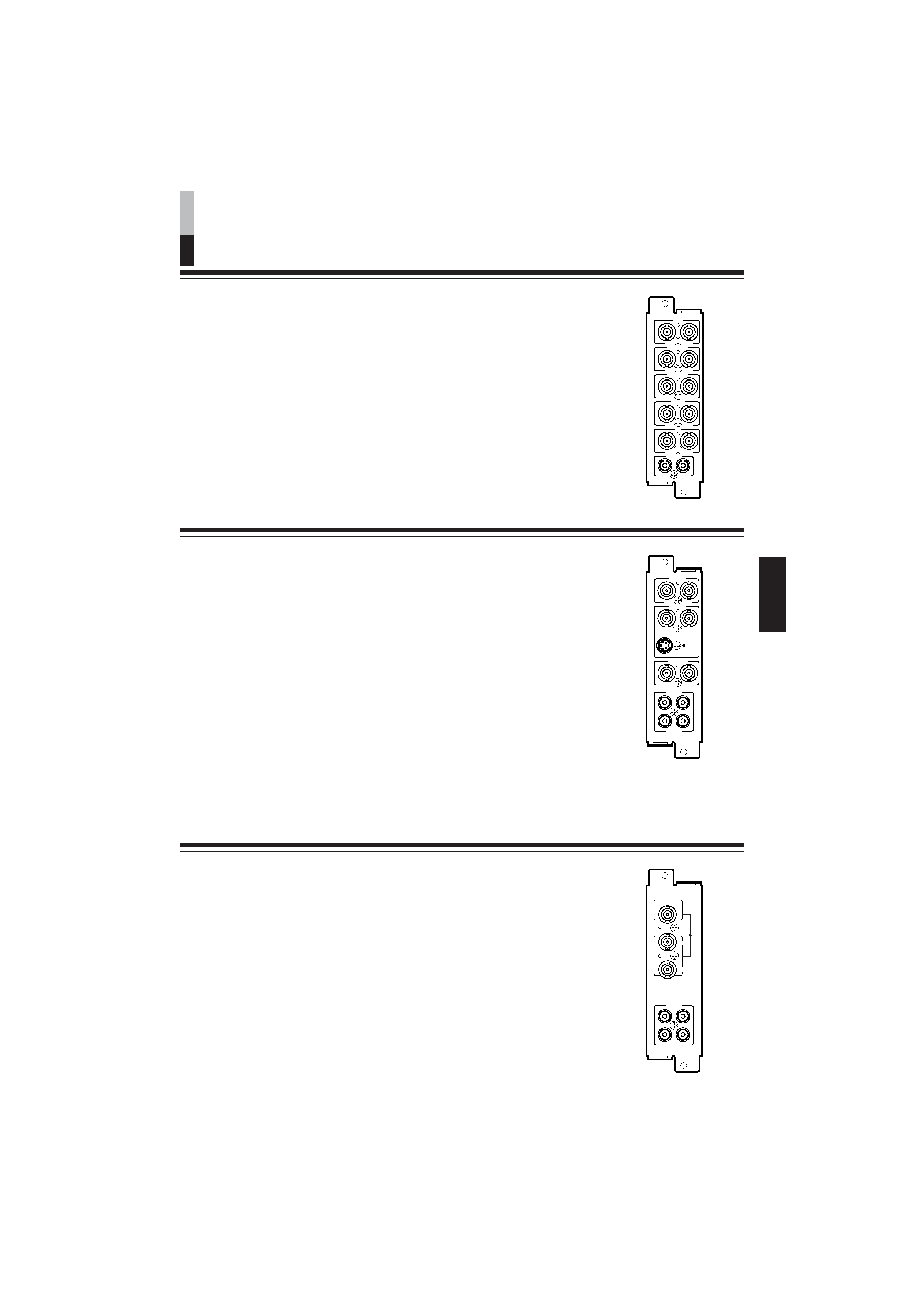
IF-C01COMG: COMPONENT/RGB INPUT CARD
Type
: TM-H Series and DT-V Series monitors
Inputs/Outputs
: Image input: Component (Y, PB/B-Y, PR/R-Y) or RGB: 1 line, BNC
connector x 6
(Y: 1 Vp-p, 75
/PB, B-Y, PR, R-Y, R, G, B: 0.7 Vp-p, 75 )
Synchronised signal (HD/CS, VD) : 1 line, BNC connector x 4
(0.3 V 4.0 Vp-p, 75
)
* The input (IN) and output (OUT) terminals are bridge-connected.
Auto termination.
Audio signal: 1 line (monaural), RCA pin x 2 (0.5 V(rms), high
impedance)
* The input (IN) and output (OUT) terminals are bridge-connected.
Required slots
:1
Power consumption : 14 V DC, 0.02 A
Weight
: 0.5 k
g
Dimensions
(W x H x D)
: 43 mm x 154.5 mm x 191.9 mm
B/PB/B-Y
G/Y
OUT
IN
OUT
IN
R/PR/B-Y
OUT
IN
VD
OUT
IN
HD/CS
OUT
IN
OUT
IN
AUDIO
OUT
IN
VIDEO1
OUT
IN
AUDIO2
AUDIO1
OUT
IN
VIDEO2
OUT
Y/C IN
IN
OUT
IN
EXT.SYNC
AUDIO2
AUDIO1
OUT
IN
SWITCHED
OUT
SDI 1
SDI 2
IN
IN
01_EN
03/4/21, 21:24
3