COPYRIGHT © 2003 VICTOR COMPANY OF JAPAN, LTD
SERVICE MANUAL
Regarding service information other than these sections, refer to the service manual No. 82948 (HR-XVC20US).
Also, be sure to note important safety precautions provided in the service manual.
GENERAL
Power supply:
Power consumption:
Weight:
Dimensions:
Inputs/Outputs:
Video:
Audio:
Antenna:
Hi-Fi Frequency Response:
Hi-Fi Dynamic Range:
VCR section
Video Head:
Audio Track:
Tuner:
RF Channel Output:
F.FWD/REW Time:
DVD section
Signal system:
Applicable disc:
Audio characteristics
Frequency response:
S/N Ratio:
Harmonic distortion
Wow and flutter:
Dynamic range:
Output:
Pickup:
ACCESSORIES:
AC 120V 60Hz
Operation: 18W
Stand by: 2W
7.9lbs (3.6 kg)
Width : 16-15/16 inches (430 mm)
Height : 3-7/8 inches (99 mm)
Depth : 9-13/16 inches (249 mm)
In: 1Vp-p/75 ohm
Out: 1Vp-p/75 ohm
In: -8 dBm/50k ohm
Out: -8 dBm/1k ohm
UHF/VHF IN/OUT: 75 ohm coaxial
20Hz to 20,000Hz
More than 90dB
4 Rotary Heads
Hi-Fi Sound - 2 Tracks / MONO Sound - 1 Track
181 Channel Freq. Synthesized
VHF
2-13
UHF
14-69
CATV
14-36 (A)-(W)
37-59 (AA)-(WW)
60-85 (AAA)-(ZZZ)
86-94 (86)-(94)
95-99 (A-5)-(A-1)
100-125 (100)-(125)
01 (5A)
Channel 3 or 4, Switchable
Approx. 1 minute 48 seconds (with T-120 Cassette Tape) (at+25
°C)
NTSC
DVD (12cm, 8cm), CD (12cm, 8cm)
DVD: 4Hz - 22kHz
CD: 4Hz - 20kHz
90dB
0.02%
Less than 0.01% Wrms
More than 90dB
Video :
(RCA) 1 Vp-p/75ohm
Audio :
(RCA) -8 dBm/1k ohm
Digital Audio : 0.5Vp-p 75 ohm
CD :
Wavelength: 775 - 805 nm
Maximum output power: 0.5 mW
DVD : Wavelength: 640 - 660 nm
Maximum output power: 1.0 mW
Remote control x 1
Batteries (2 x AA)
75 ohm Coaxial Cable x 1
AUDIO/VIDEO Cable x 1
No.82989
2003/07
HR-XVC20US(R)
HR-XVC20US(R) D2VP11
DVD/CD PLAYER Hi-Fi STEREO VIDEO CASSTTE RECORDER
SPECIFICATIONS
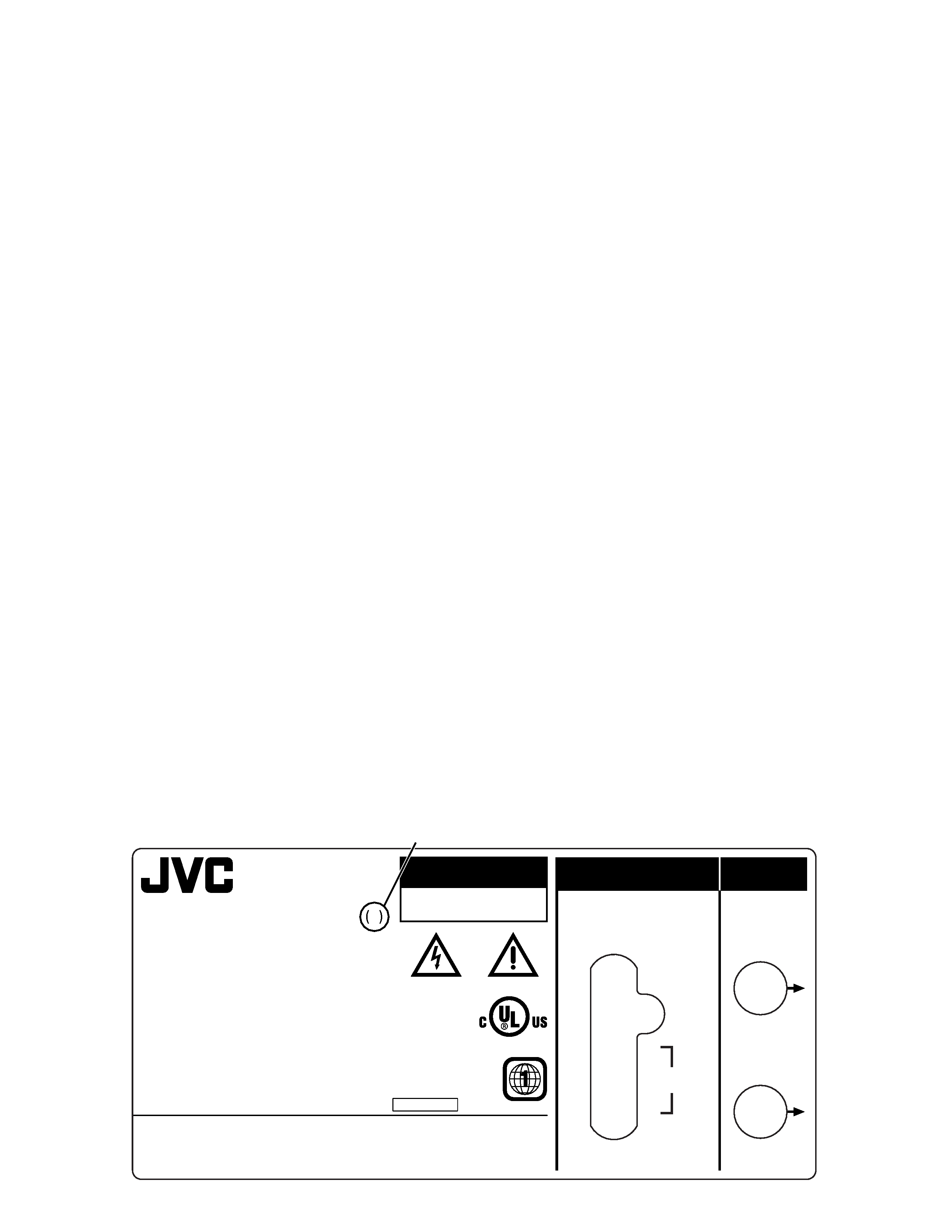
TABLE OF CONTENTS
Section
Title
Page
Section
Title
Page
HOW TO IDENTIFY MODELS
DISASSEMBLY INSTRUCTIONS
1. REMOVAL OF MECHANICAL PARTS AND P.C.BOARDS ............... 1-1
1-1 TOP CABINET AND FRONT CABINET ............................ 1-1
1-2 FLAP .................................................................................. 1-1
1-3 DVD DECK ........................................................................ 1-1
1-4 DVD PCB ........................................................................... 1-2
1-5 VCR DECK ........................................................................ 1-2
1-6 VCR PCB ........................................................................... 1-2
4. REMOVAL OF DVD DECK PARTS ......................................... 1-3
4-1 TRAY .................................................................................. 1-3
4-2 MAIN CHASSIS ASS'Y ...................................................... 1-3
4-3 RACK LOADING / MAIN GEAR / RACK LOADING SPRING / RACK L SPRING .. 1-3
4-4 CLAMPER ASS'Y / INSULATOR(R) / LEVER SWITCH .... 1-3
4-5 TRAVERSE HOLDER / INSULATOR(F) ............................ 1-4
4-6 SWITCH PCB ASS'Y ......................................................... 1-4
4-7 RACK FEED ASS'Y ........................................................... 1-4
4-8 RELAY PCB ASS'Y ............................................................ 1-5
4-9 GEAR ................................................................................. 1-5
4-10 IDLER ARM ..................................................................... 1-5
4-11 FEED MOTOR ................................................................. 1-6
ELECTRICAL ADJUSTMENT PARTS LOCATION GUIDE .............. 1-7
WHEN REPLACING EEPROM(MEMORY) IC ........................... 1-8
SERVO TIMING CHART ............................................................ 1-8
CHARTS AND DIAGRAMS
INTERCONNECTION DIAGRAM ............................................ 2-1
Y/C/AUDIO/CCD/HEAD AMP SCHEMATIC DIAGRAM .......... 2-3
SYSCON SCHEMTAIC DIAGRAM .......................................... 2-5
TUNER/JACK SCHEMATIC DIAGRAM .................................. 2-7
OPERATION/DISPLAY SCHEMATIC DIAGRAM .................... 2-9
HI-FI/DEMODULATOR SCHEMATIC DIAGRAM .................. 2-11
POWER SCHEMATIC DIAGRAM ......................................... 2-13
OPERATION/LED SCHEMATIC DIAGRAM .......................... 2-15
SW/RELAY/FG SCHEMATIC DIAGRAM .............................. 2-17
MPEG/MICOM SCHEMATIC DIAGRAM ............................... 2-19
MEMORY SCHEMATIC DIAGRAM ....................................... 2-21
RF AMP/DSP SCHEMATIC DIAGRAM ................................. 2-23
AUDIO/VIDEO SCHEMATIC DIARAM .................................. 2-25
PRINTED CIRCUIT BOARD VCR ......................................... 2-27
PRINTED CIRCUIT BOARD DVD ......................................... 2-31
PRINTED CIRCUIT BOARD OPERATION ............................ 2-34
PARTS LIST
3.1 EXPLODED VIEW ................................................................ 3-1
3.1.1 PACKING AND ACCESSORY ASSEMBLY<M1> .......... 3-1
3.1.2 FINAL ASSEMBLY<M2> ................................................ 3-2
3.1.3 MECHANISM ASSEMBLY(DVD)<MN> .......................... 3-3
3.1.4 MECHANISM ASSEMBLY(VCR)<M4> .......................... 3-4
3.2 ELECTRICAL PARTS LIST .................................................. 3-6
PACKING AND ACCESSORY ASSEMBLY<M1> .................... 3-6
FINAL ASSEMBLY<M2> .......................................................... 3-6
MECHANISM ASSEMBLY(VCR)<M4> .................................... 3-6
MECHANISM ASSEMBLY(DVD)<MN> ................................... 3-7
VCR BOARD ASSEMBLY<03> ............................................... 3-7
OPERATION BOARD ASSEMBLY<28> ................................ 3-12
DVD BOARD ASSEMBLY<50> .............................................. 3-12
CAUTION
RISK OF ELECTRIC SHOCK
DO NOT OPEN
AVIS:RISQUE DE CHOC ELECTRIQUE-NE PAS OUVRIR
LI S T E D
44 L 6
E68219 CAT. M2C58
VIDEO SYSTEM
FCC ID : A7RM2C5A
CHASSIS:M2C58
KD
DVD/VIDEO CASSETTE RECORDER
AC/CA 120V 60Hz 18W
Confidential unpublished works. ©1992-1997 Dolby Laboratories. All rights reserved.
"Dolby" and the double-D symbol are trademarks of Dolby Laboratories.
Manufactured under license from Dolby Laboratories.
and 4,907,093 licensed for limited viewing uses only.
Apparatus Claims of U.S. Patent Nos. 4,631,603;4,577,216;4,819,098
"DTS" and "DTS Digital Out" are trademarks of Digital Theater Systems, lnc.
CERTIFICATION : COMPLIES WITH FDA RADIATION PERFORMANCE STANDARDS, 21 CFR SUBCHAPTER J.
THIS DEVICE COMPLIES WITH PART 15 OF THE FCC RULES.
CABLE COMPATIBLE TELEVISION APPARATUS-TÉLÉVISION CÂBLOCOMPATIBLE, CANADA
OPERATION IS SUBJECT TO THE FOLLOWING TWO CONDITIONS : 1 THIS DEVICE MAY NOT
CAUSE HARMFUL INTERFERENCE, AND 2 THIS DEVICE MUST ACCEPT ANY INTERFERENCE
RECEIVED, INCLUDING INTERFERENCE THAT MAY CAUSE UNDESIRED OPERATION.
DISTRIBUT PAR JVC CANADA, INC. 21 FINCHDENE SQUARE, SCARBOROUGH, ONTARIO.MIX 1A7.
DISTRIBUTED BY JVC CANADA, INC. 21 FINCHDENE SQUARE, SCARBOROUGH, ONTARIO.MIX 1A7.
DISTRIBUTED BY JVC AMERICAS CORP., 1700 VALLEY ROAD, WAYNE, N.J. 07470
DISTRIBUTOR / DISTRIBUTEUR
MANUFACTURED/FABRIQU
¸ :
SERIAL NO./NO.DE SERIE
MADE IN THAILAND/FABRIQUE EN THAILANDE
( )
( )
VHF/UHF
DVD/VCR OUTPUT
VIDEO
AUDIO
L
R
IN
ANT
(
)
OUT
TV
(
)
722538A048
MODEL/MODELE NO. HR-XVC20U R
[blank] : HR-XVC20US
(R) : HR-XVC20US(R)
RATING LABEL
How to recognize from the appearance of the model concerned is written below.
Please distinguish from several contents currently printed on the rating label of the rear panel.
HOW TO IDENTIFY MODELS
1-1
DISASSEMBLY INSTRUCTIONS
1
1
2
Top Cabinet
Front Cabinet
1
1
2
2
2
2
2
1
2
1.
1-1:
Fig. 1-1
REMOVAL OF MECHANICAL PARTS
AND P.C. BOARDS
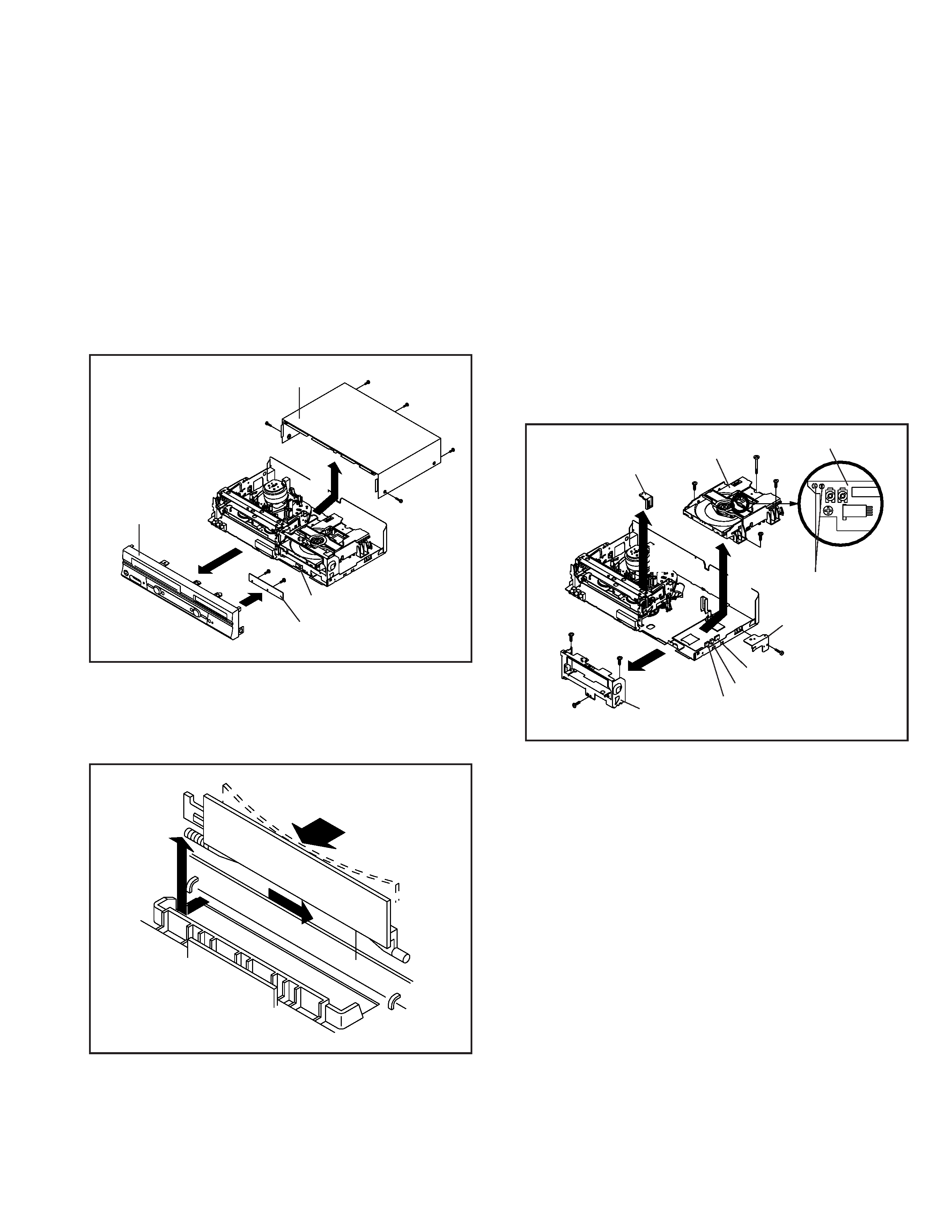
TOP CABINET AND FRONT CABINET
(Refer to Fig. 1-1)
1.
2.
3.
4.
5.
6.
7.
Remove the 5 screws
1.
Remove the Top Cabinet in the direction of arrow (A).
Disconnect the following connector: (CP651).
Unlock the 8 supports
2.
Remove the Front Cabinet in the direction of arrow (B).
Remove the 2 screws
3.
Remove the Operation PCB in the direction of arrow (C).
1-2: FLAP (Refer to Fig. 1-2)
1.
2.
Open Flap to 90° and flex in direction of arrow (A), at the
same time slide in direction of arrow (B).
Then lift in direction of arrow (C).
Fig. 1-2
(A)
Flap
(B)
(C)
(B)
3
3
Operation PCB
CP651
2
(A)
(C)
1.
2.
3.
4.
5.
6.
7.
8.
9.
10.
11.
Make the short circuit on the position as shown Fig. 1-3
using a soldering. If you remove the DVD Deck with no
soldering, the Laser may be damaged.
Unlock the support
1 and remove the Deck Top Holder
in the direction of arrow (A).
Remove the 2 screws
2.
Remove the screw
3.
Remove the screw
4.
Disconnect the following connectors: (CP2601, CP2602,
CP2603).
Remove the DVD Deck in the direction of arrow (B).
Remove the 3 screws
5.
Remove the Front Angle in the direction of arrow (C).
Remove the screw
6.
Remove the DVD Angle.
Fig. 1-3
1-3: DVD DECK (Refer to Fig. 1-3)
NOTE
When the installation of the DVD Deck, remove all the
soldering on the short circuit position after the connection of
Pick Up PCB and DVD PCB connector.
1
Make the sort circuit
using a soldering.
Pick Up PCB
Deck Top Holder
(A)
2
2
4
3
5
DVD Deck
(C)
Front Angle
5
5
(B)
CP2603
CP2602
CP2601
6
DVD Angle
1-2
DISASSEMBLY INSTRUCTIONS
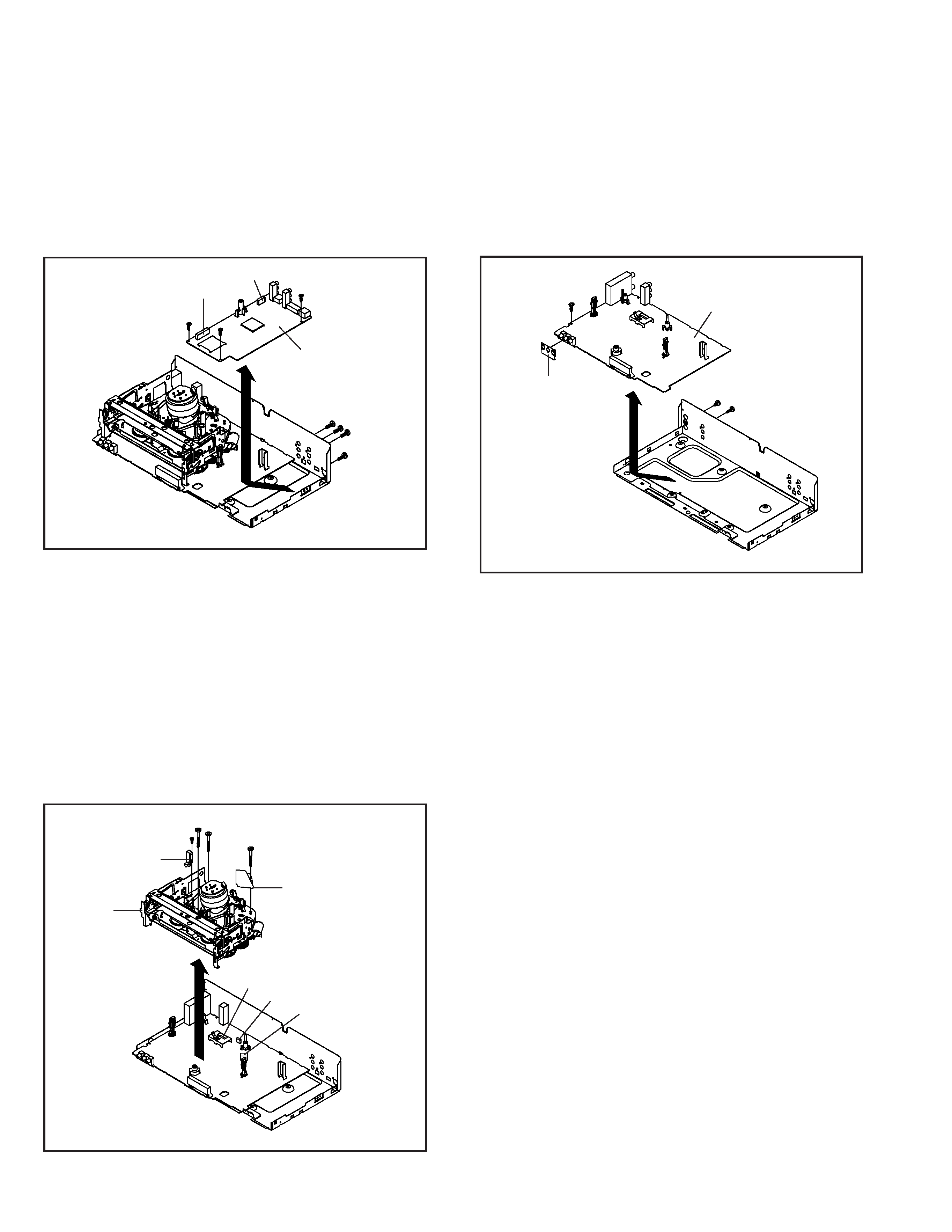
1-6: VCR PCB (Refer to Fig. 1-6)
1.
2.
3.
4.
5.
Remove the screw 1.
Remove the screw 2.
Remove the screw 3.
Remove the 3 Pin Shield.
Remove the VCR PCB in the direction of arrow.
Fig. 1-6
1
VCR Deck
1-5: VCR DECK (Refer to Fig. 1-5)
1.
2.
3.
4.
5.
6.
Move the Cassette Holder Ass'y to the back side.
Remove the screw 1.
Remove the FE Head.
Remove the 3 screws 2.
Disconnect the following connectors: (CP101, CP102,
and CP3001).
Remove the AC Head Cover and VCR Deck in the
direction of arrow.
3
VCR PCB
1-4: DVD PCB (Refer to Fig. 1-4)
1.
2.
3.
4.
Remove the 3 screws 1.
Remove the 4 screws 2.
Disconnect the following connectors: (CP4002 and
CP8102).
Remove the DVD PCB in the direction of arrow.
Fig. 1-4
Do not remove the cable at the FE Head section. The FE
Head may be damaged if you remove the cable by force.
NOTE
Fig. 1-5
2
FE Head
2
CP101
CP102
CP3001
AC Head Cover
2
1
2
3 Pin Shield
1
1
DVD PCB
2
2
2
2
1
CP4002
CP8102
1-3
DISASSEMBLY INSTRUCTIONS
4. REMOVAL OF DVD DECK PARTS
NOTE
1. Do not disassemble the DVD DECK PARTS except listed
parts here. Minute adjustments are needed if the disas-
semble is done. If the repair is needed except listed parts,
replace the DVD MECHA ASS'Y.
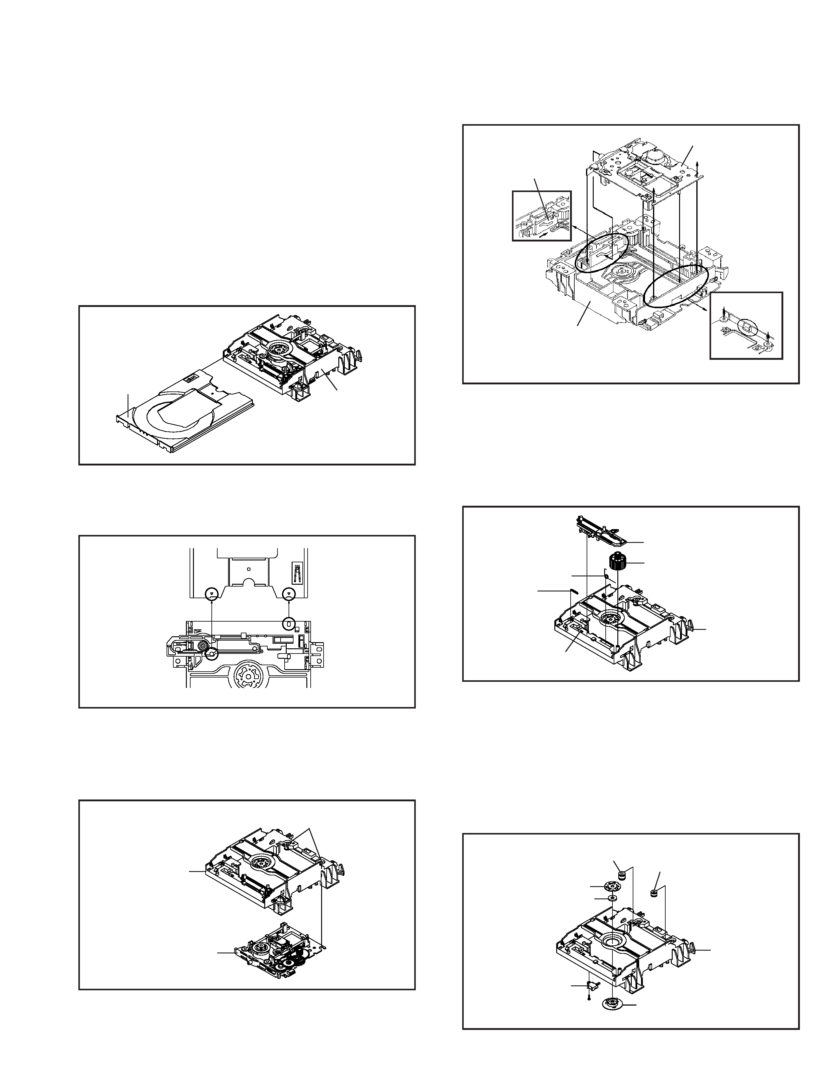
4-1: TRAY (Refer to Fig. 4-1-A)
1.
2.
Set the Tray opened. (Refer to the DISC REMOVAL
METHOD AT NO POWER SUPPLY)
Unlock the support 1 and remove the Tray.
Main Frame Ass'y
1
Tray
Fig. 4-1-A
NOTE
1. In case of the Tray installation, install them as the circled
section of Fig. 4-1-B so that the each markers are met.
Fig. 4-1-B
Tray
Main Frame Ass'y
4-2: MAIN CHASSIS ASS'Y (Refer to Fig. 4-2-A)
1.
2.
3.
Remove the Main Chassis Ass'y from the Insulator (R).
Unlock the support 1.
Remove the Main Chassis Ass'y.
Fig. 4-2-A
Insulator (R)
(Green)
1
Main Frame Ass'y
Main Chassis Ass'y
4-3: RACK LOADING/MAIN GEAR/ RACK LOADING
SPRING/ RACK L SPRING (Refer to Fig. 4-3)
1.
2.
3.
Remove the Rack L Spring.
Press down the catcher 1 and slide the Rack Loading.
Remove the Rack Loading, Rack Loading Spring and
Main Gear.
Fig. 4-3
4-4: CLAMPER ASS'Y/INSULATOR(R)/LEVER SWITCH
(Refer to Fig. 4-4-A)
1.
2.
3.
4.
5.
Remove the screw 1.
Remove the Lever Switch.
Remove the 2 Insulator (R).
Press the Clamper and rotate the Clamper Plate clockwise,
then unlock the 3 supports 2.
Remove the Clamper Plate, Clamper Magnet and Clamper.
Insulator (R)
(Green)
Insulator (R)
(Green)
Clamper Plate
Clamper Magnet
Main Frame
Lever Switch
Clamper
1
2
2
2
Fig. 4-4-A
Fig. 4-2-B
Main Chassis Ass'y
Rack Loading
Move it to the direction
of the arrow.
Main Frame Ass'y
1
Check Lock
2
3
4
5
6
6
5
4
Rack Loading Spring
Rack Loading
Main Gear
1
Main Frame Ass'y
NOTE
1. In case of the Main Chassis Ass'y, install it from (1) to (6)
in order. (Refer to Fig. 4-2-B)
Rack L Spring