COPYRIGHT © 2002 VICTOR COMPANY OF JAPAN, LTD
This service manual is printed on 100% recycled paper.
SERVICE MANUAL
Regarding service information other than these sections, refer to the service manual No. 82921 (HR-XVC1UJ).
Also, be sure to note important safety precautions provided in the service manual.
GENERAL
Power supply:
Power consumption:
Weight:
Dimensions:
Inputs/Outputs:
Video:
Audio:
Antenna:
Hi-Fi Frequency Response:
Hi-Fi Dynamic Range:
VCR section
Video Head:
Audio Track:
Tuner:
RF Channel Output:
F.FWD/REW Time:
DVD section
Signal system:
Applicable disc:
Audio characteristics:
Frequency response:
S/N Ratio:
Harmonic distortion:
Wow and flutter:
Dynamic range:
Output:
Pickup:
ACCESSORIES:
110-220V, 50/60 Hz
Operation: 22W
Stand by: 4W
9.9lbs (4.5 kg)
Width : 16-15/16 inches (430 mm)
Height :
3-7/8 inches (99 mm)
Depth : 12-1/4 inches (311 mm)
In: 1Vp-p/75 ohm
Out: 1Vp-p/75 ohm
In: -8 dBm/50K ohm
Out: -8 dBm/1K ohm
UHF/VHF IN/OUT: 75 ohm coaxial
20Hz to 20,000Hz
More than 90dB
4 Rotary Heads
Hi-Fi Sound - 2 Tracks / MONO Sound - 1 Track
181 Channel Freq. Synthesized
VHF
2-13
UHF
14-69
CATV
14-36 (A)-(W)
37-59 (AA)-(WW)
60-85 (AAA)-(ZZZ)
86-94 (86)-(94)
95-99 (A-5)-(A-1)
100-125 (100)-(125)
01 (5A)
Channel 3 or 4, Switchable
Approx. 1 minute 48 seconds
(with T-120 Cassette Tape) (at+25
°C)
NTSC
DVD (12cm, 8cm), CD (12cm, 8cm)
DVD: 4Hz - 22KHz
CD: 4Hz - 20KHz
90dB
0.02%
Below Measurable Level
90dB
Video :
(RCA) 1 Vp-p/75ohm
Audio :
(RCA) -8 dBm/1Kohm
Digital Audio : 0.5Vp-p 75 ohm
CD :
Wavelength: 775 - 805 nm
Maximum output power: 0.5 mW
DVD : Wavelength: 640 - 660 nm
Maximum output power: 1.0 mW
Remote control x 1
Batteries (2 x AA)
75 ohm Coaxial Cable x 1
AUDIO/VIDEO Cable x 1
Conversion plug x 1
No.82921B
September 2002
HR-XVC1UJ/M
HR-XVC1UJ/M V14PV1
DVD/CD PLAYER Hi-Fi STEREO VIDEO CASSETTE RECORDER
SPECIFICATIONS
POWER
TV
TV VOL
0
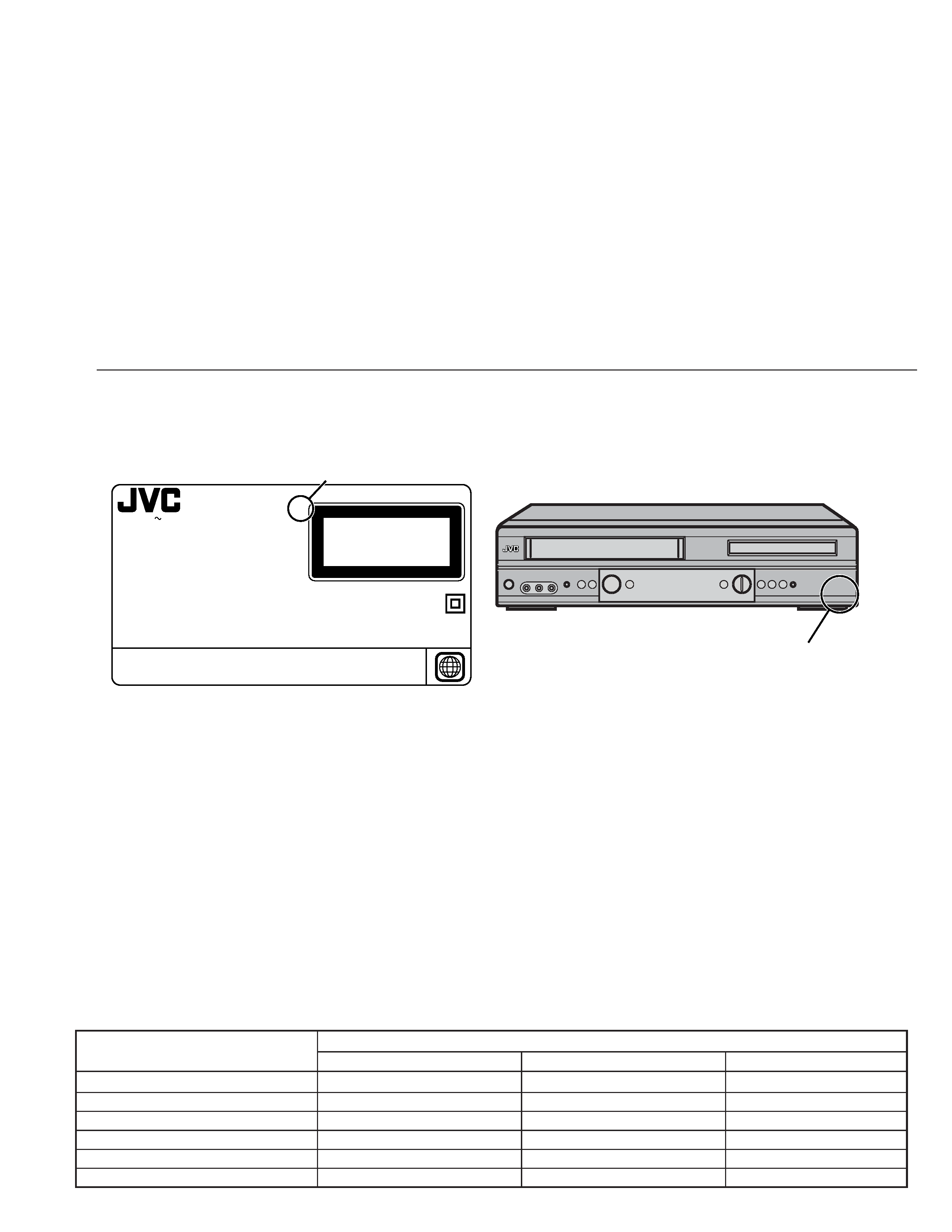
TABLE OF CONTENTS
HOW TO IDENTIFY MODELS .................................................................... 1
Circuit board assembly and unit compatibility between
HR-XVC1UJ and HR-XVC1UJ/M ..................................................... 1
DIFFERENT TABLE ................................................................................... 2
DISASSEMBLY INSTRUCTIONS
1. REMOVAL OF MECHANICAL PARTS AND P.C. BOARDS .......... 1-1
1-5. DECK CD AND DVD MT PCB ................................................. 1-1
SERVICE MODE LIST ....................................................................... 1-1
WHEN REPLACING EEPROM(MEMORY) IC .................................. 1-2
SERVO TIMING CHART ................................................................... 1-2
PREPARATION FOR SERVICING .................................................... 1-3
ELECTRICAL ADJUSTMENTS ........................................................ 1-3
2. ELECTRICAL ADJUSTMENT PARTS LOCATION GUIDE
(Connector Connections) ......................................................... 1-3
2. CHARTS AND DIAGRAMS (2-1 to 2-36)
INTERCONNECTION DIAGRAM ............................................ 2-1
MPEG SCHEMATIC DIAGRAM ............................................... 2-3
MEMORY SCHEMATIC DIAGRAM ......................................... 2-5
1
SYSCON1 SCHEMATIC DIAGRAM ........................................ 2-7
DSP SCHEMATIC DIAGRAM .................................................. 2-9
MOTOR DRIVE SCHEMATIC DIAGRAM ............................... 2-11
READ CHANNEL SCHEMATIC DIAGRAM ........................... 2-13
AUDIO/VIDEO SCHEMATIC DIAGRAM ................................ 2-15
Y/C/AUDIO/CCD/HEAD AMP SCHEMATIC DIAGRAM ......... 2-17
VCR SYSCON SCHEMATIC DIAGRAM ................................ 2-19
TUNER/JACK SCHEMATIC DIAGRAM ................................. 2-21
REGULATOR SCHEMATIC DIAGRAM ................................. 2-23
OPERATION/DISPLAY SCHEMATIC DIAGRAM ................... 2-25
HI-FI/DEMODULATOR SCHEMATIC DIAGRAM ................... 2-27
DVD IN/OUT SCHEMATIC DIAGRAM ................................... 2-29
PRINTED CIRCUIT BOARDS DVD ....................................... 2-31
PRINTED CIRCUIT BOARDS VCR ....................................... 3-33
3. PARTS LIST (3-1 to 3-7)
3.1
PACKING AND ACCESSORY ASSEMBLY <M1> ................... 3-1
3.2
ELECTRICAL PART LIST
VCR BOARD ASSEMBLY<03> .................................................. 3-2
DVD BOARD ASSEMBLY<50> .................................................. 3-6
DVD/VIDEO CASSETTE RECORDER
MODEL NO. HR-XVC1UJ/M
SERIAL NO.
110-220V
50/60Hz 22W
722538A036
VICTOR COMPANY OF JAPAN, LTD.
KD
1
CLASS 1
LASER PRODUCT
Confidential unpublished works. ©1992-1997 Dolby Laboratories. All rights reserved.
"Dolby" and the double-D symbol are trademarks of Dolby Laboratories.
Manufactured under license from Dolby Laboratories.
4,631,603;4,577,216;4,819,098 and 4,907,093 licensed for limited viewing uses only.
Apparatus Claims of U.S. Patent Nos.
"DTS" and "DTS Digital Out" are trademarks of Digital Theater Systems, lnc.
WARNING : DANGEROUS VOLTAGE INSIDE.
(blank) : HR-XVC1UJ
/M : HR-XVC1UJ/M
RATING LABEL
"SPECIALIZER" logo mark
3D STEREO : HR-XVC1UJ
N-2-2 : HR-XVC1UJ/M
HOW TO IDENTIFY MODELS
How to recognize from the appearance of the model concerned is written below.
Please distinguish from several contents currently printed on the rating label of the rear panel or "SPECIALIZER" logo mark of the front
panel.
Circuit board assembly and unit compatibility between HR-XVC1UJ and HR-XVC1UJ/M
Since the same parts are used for the VCR mechanism section and power supply circuit board assembly for the HR-XVC1UJ and HR-
XVC1UJ/M, they are interchangeable. However, there is no compatibility for the VCR circuit board, DVD circuit board, and DVD drive unit.
1. The difference in the VCR circuit board is the connection cable that connects to the DVD circuit board. It is not possible to connect an
old board to a new board.
2. The difference in the DVD circuit board is the substantial difference in external dimensions. There is also no compatibility in terms of
specifications.
<Reference>
When an old VCR circuit board is forcibly connected to a new DVD circuit board, there is a terminal that changes HR-XVC1UJ:
3.3V
HR-XVC1UJ/M: 9V and the DVD circuit board will be damaged.
3. It is possible to install the DVD drive unit in the chassis. However, since there is no compatibility between the DVD circuit board and the
connection cable, it is not possible to connect old and new together.
<Reference>
If the entire set of revised parts is exchanged at once (DVD drive unit, VCR circuit board, DVD circuit board (with attachment angle)),
the specifications for Spatializer will change from 3D Stereo
N-2-2. This type of process will cause non-compliance with certified
specifications, so do not interchange old and new type parts.
Compatibility
DVD drive unit
Yes
No
--
DVD circuit board
No
No
No
DVD circuit board attachment angle
No
--
--
VCR mechanism unit
Yes
Yes
--
VCR circuit board
Yes
Yes
No
Power supply circuit board
Yes
Yes
--
Old/New Parts Compatibility
Mechanical specifications (installation) Electrical specifications (connection)
Software specifications
The following table indicates main different points between models HR-XVC1UJ and HR-XVC1UJ/M.
MODEL
HR-XVC1UJ
ITEM
SPECIALIZER
3D STEREO
N-2-2
HR-XVC1UJ/M
The following table indicates different parts number between models HR-XVC1UJ and HR-XVC1UJ/M.
PACKING AND ACCESSORY ASSEMBLY<M1>
PACKING AND ACCESSORY ASSEMBLY<M1> is indicated on the parts list.
VCR BOARD ASSEMBLY<03>
REF
NO.
!
MODEL
ITEM
PCB010 VCR BOARD ASSY
X-A2A309E010
X-A2B005C010
HR-XVC1UJ
HR-XVC1UJ/M
REF
NO.
!
MODEL
ITEM
601
CABINET,FRONT ASSY
X-A2A309E720
X-A2B005C720
606
HOLDER,EOT SENSOR
X-85OP700036
X-85OP700038
608
CABINET,FRONT
X-701WPJB699
X-701WPJB838
610
FLAP
X-712WPJB411
X-712WPJ0758
617
SPRING,FLAP
X-743WKA0039
X-743WKA0042
619
PLATE,BOTTOM
X-702WSA0109
X-702WSA0117
621
SHEET,IC
X-7230007414
X-7230007426
624
SHIELD,FRONT
X-753WSA0148
X-753WSA0153
627
ANGLE,DECK1/ANGLE,DECK X-761WSA0085
X-761WSA0096
628
ANGLE,DECK2/HOLDER,FFC X-761WSA0086
X-761WPA0250
633
CABINET,BOTTOM ASSY X-A2A309E730
X-A2B005C730
634
SHIELD,M-PEG/SHEET,IC X-752WSA0279
X-7230007461
635
SPRING,EARTH
X-753WUA0061
X-744WUA0013
636
SHEET,PVC/CORD CLIP X-755WNA0015
X-8995034000
637
SHEET,PVC
X-755WNA0016
--
708
SCREW
--
X-8109I30804
CD102 CORD,JUMPER
X-122F061501
X-122F061502
CD503 CORD,CONNECTOR
X-06CU262201
--
CD2301 CORD,JUMPER
--
X-122H081007
CD2302 CORD,CONNECTOR
--
X-06CU251002
CD2601 CORD,JUMPER
--
X-122H0O2102
CD8002 CORD,JUMPER
X-122S0I2001
X-122H0I1801
!DK4001 DECK CD
X-169G00012A
X-169G00014A
HR-XVC1UJ
HR-XVC1UJ/M
FINAL ASSEMBLY<M2>
REF
NO.
!
MODEL
ITEM
2
CORD,RCA PIN
X-06CQBA2001
X-06CPBA2003
8
GIFT BOX
X-793WCDB269
X-793WCDB398
12
INSTRUCTION BOOK
X-J2A30901
X-J2B00501A
HR-XVC1UJ
HR-XVC1UJ/M
PACKING AND ACCESSORY ASSEMBLY<M1>
DVD BOARD ASSEMBLY<50>
REF
NO.
!
MODEL
ITEM
PCB130 DVD BOARD ASSY
--
X-A2B005C130
HR-XVC1UJ
HR-XVC1UJ/M
Note: Mark
is same as left.
Mark -- is not used.
MPEG MT BOARD ASSEMBLY<50>
REF
NO.
!
MODEL
ITEM
PCB120 MPEG MT BOARD ASSY X-A2A309E120
--
HR-XVC1UJ
HR-XVC1UJ/M
2
1-1
1. REMOVAL OF MECHANICAL PARTS
AND P.C. BOARDS
1.
2.
3.
4.
5.
6.
7.
8.
9.
10.
11.
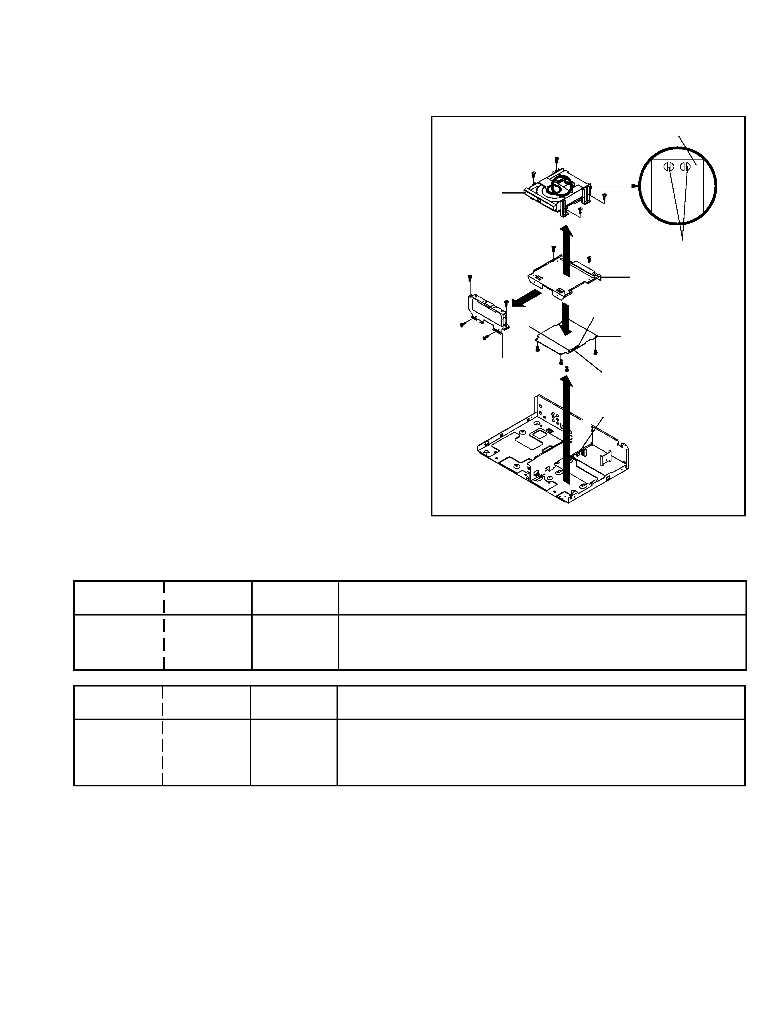
Make the short circuit on the position as shown Fig. 1-5
using a soldering. If you remove the Deck CD with no
soldering, the Laser may be damaged.
Disconnect the following connector: (CP503).
Remove the 4 screws 1.
Remove the Deck Angle in the direction of arrow (A).
Remove the 2 screws 2.
Remove the Front Shield in the direction of arrow (B).
Disconnect the following connectors: (CP2301, CP2302
and CP2601).
Remove the 4 screws 3.
Remove the Deck CD in the direction of arrow (C).
Remove the 4 screws 4.
Remove the DVD MT PCB in the direction of arrow (D).
1-5: DECK CD AND DVD MT PCB (Refer to Fig. 1-5)
When the installation of the Deck CD, remove all the solder-
ing on the short circuit position after the connection of Pick
Up PCB and DVD MT PCB connector.
NOTE
DISASSEMBLY INSTRUCTIONS
Fig. 1-5
2
DVD MT PCB
1
2
4
Deck CD
(C)
(D)
Deck Angle
Front-DVD Shield
3
(A)
(B)
1
1
1
3
3
3
4
4
4
Make the sort circuit
using a soldering.
Pick Up PCB
CP2601
CP2602
CP2603
CP503
SERVICE MODE LIST
Set Key
Operations
Set Key
Standard Time
(seconds)
CH DOWN
POWER
2
VCR operation mode at no connection of DVD.
Refer to the "PREPARATION FOR SERVICING"
NOTE: Although the DVD is connected, the DVD mode cannot be selected.
REC
5
2
Initialization of the factory on DVD.
NOTE: The function will only work without the setting of DVD disc at DVD
mode.
Do not use this for the normal servicing.
Set Key
Operations
Remocon Key
Standard Time
(seconds)
1-2
WHEN REPLACING EEPROM (MEMORY) IC
If a service repair is undertaken where it has been required to change the MEMORY IC, the following steps should be taken to
ensure correct data settings while making reference to TABLE 1.
NOTE: No need setting for after INI 2D.
Table 1
1.
2.
3.
4.
5.
6.
7.
8.
9.
The unit will now have the correct DATA for the new MEMORY IC.
Connect the set to TV Monitor.
Turn on the POWER.
Press both CH UP button on the set and the FF button on the set for more than 2 seconds.
ADDRESS and DATA will appear on TV Monitor as Fig 1.
ADDRESS is now selected and should "blink". Using the SET + or - button on the remote, step
through the ADDRESS until required ADDRESS to be changed is reached.
Press ENTER to select DATA. When DATA is selected, it will "blink".
Again, step through the DATA using SET + or - button until required DATA value has been selected.
Pressing ENTER will take you back to ADDRESS for further selection if necessary.
Repeat steps 4 to 7 until all data has been checked.
When satisfied correct DATA has been entered, turn POWER off (return to STANDBY MODE) to
finish DATA input.
INI
+0
+1
+2
+3
+4
+5
+6
+7
+8
+9
+A
+B
+C
+D
+E
+F
00
0A
30
9A
24
64
64
4A
86
0B
2F
86
34
8A
08
0A
0F
10
AF
97
95
8A
A0
55
31
04
88
A5
9F
3A
00
10
BF
00
20
29
02
00
71
66
31
29
04
00
00
00
05
A2
B0
00
---
Fig. 1
INIT 00 0A
PLAY/REC
0010
ADDRESS DATA
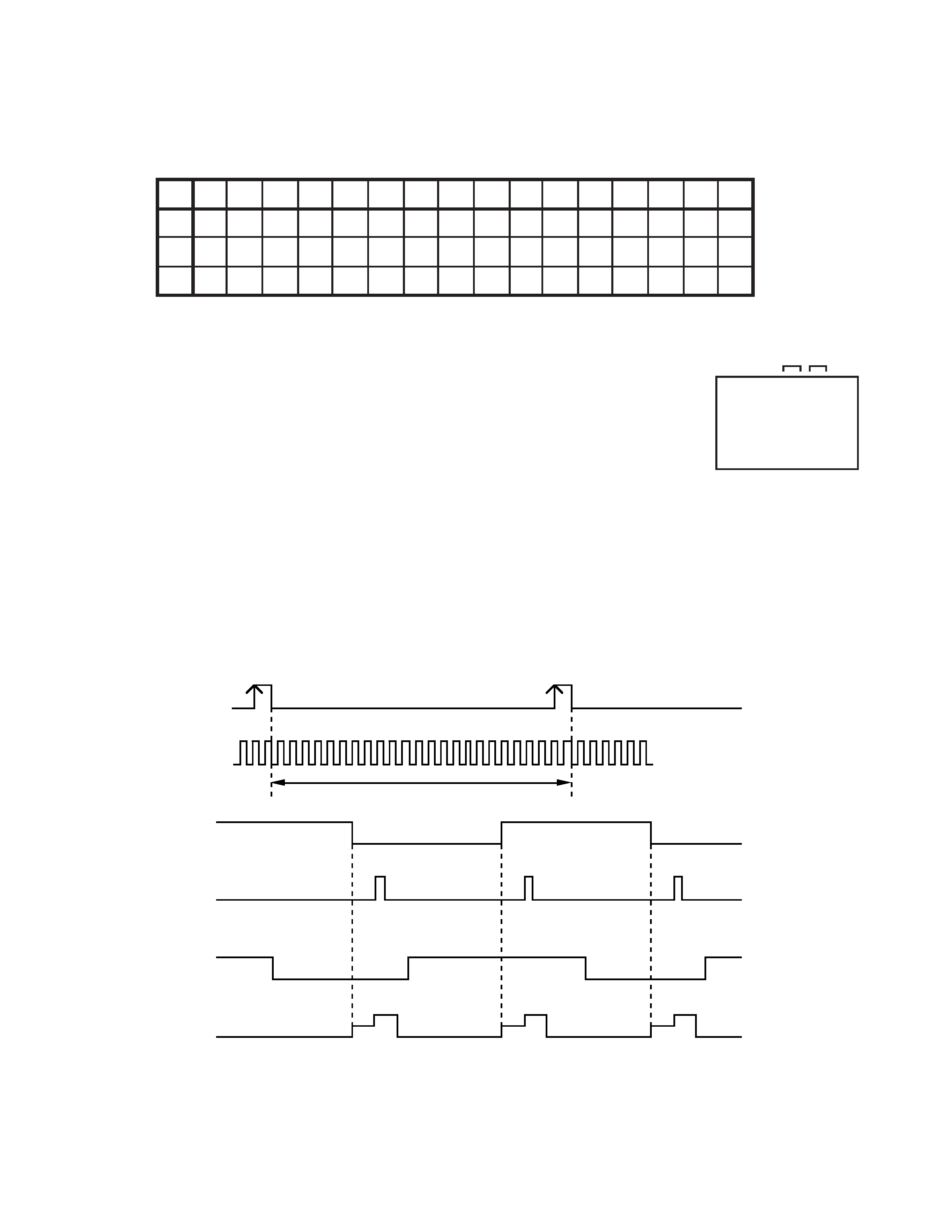
SERVO TIMING CHART
VCR MT PCB IC3001 (OEC0125A)
DPG 104 PIN
DFG 104 PIN
H. SW. P 105 PIN
V-SYNC (E-E) 111 PIN
24 Cycle
CH 1
CH 2
REC CTL (REC)
7 PIN
V-SYNC (TRICK PB)
109 PIN
· WAVEFORM CHANGES DEPENDED ON THE TAPE SPEED