VIDEO CASSETTE RECORDER
INSTRUCTIONS
LPT0002-0K7A
HR-S9400EE
625
SCE
NE FIN
DER
PROG CHE
CK
TV VOL
C.MEMORY DISPLAY
DAILY
AUX
ADD TIME
C.RESET
CANCEL
DATE
STOP
START
AUDIO MONITOR
(MONITOR)
TV/VCR
TV
SAT
VCR
TIMER
WEEKLY
A
12
45
3
6
8
0
7
9
B
PUSH JOG
MULTI BRAND
REMOTE CONTROL UNIT
TV
PROG
PRO
G/ME
NU
OK
EXPRESS PROGRAMMING
2
4
1
3
TIMER
STANDBY/ON
PULL-OPEN
8
SLO
W
SLOW
REW
FF
TV PROG/
JOG
SHUTTLE
SP/LP
+8
4
0
6
10
20dB
NORM
L
R
M
SP LP
REMAIN
REVIEW
EN
CONTENTS
ENGLISH
SAFETY FIRST
2
Safety Precautions ............................. 2
INSTALLING YOUR NEW RECORDER
4
Basic Connections ............................ 4
S-VIDEO Connection ........................ 6
INITIAL SETTINGS
8
Auto Set Up ...................................... 8
Language Set .................................... 9
Video Channel Set .......................... 10
Clock Set ........................................ 12
On-Screen Displays ........................ 13
PLAYBACK
14
Basic Playback ................................ 14
Playback Features ........................... 15
TimeScan ........................................ 20
RECORDING
22
Basic Recording .............................. 22
Recording Features ......................... 23
INFORMATION ON SIGNAL
CONVERSION SYSTEM
26
TIMER RECORDING
28
SHOWVIEW Setup ............................. 28
SHOWVIEW Timer Recording ............ 30
Regular Timer Programming ........... 32
SPECIAL FEATURES
36
TV Multi-Brand Remote Control ..... 36
Satellite Tuner Multi-Brand
Remote Control .............................. 37
EDITING
38
Preparation For Editing ................... 38
Edit To Or From Another Video
Recorder ......................................... 40
Edit From A Camcorder .................. 42
Audio Dubbing ............................... 43
Insert Editing ................................... 44
Random Assemble Editing .............. 46
INFORMATION ON J TERMINAL
49
SYSTEM CONNECTIONS
50
Connection to A Stereo System ......... 50
TUNER SET
51
TROUBLESHOOTING
56
QUESTIONS AND ANSWERS
59
INDEX
60
SPECIFICATIONS
63
2 EN
SAFETY FIRST
Safety Precautions
The rating plate and the safety caution are on the rear of the unit.
WARNING: DANGEROUS VOLTAGE INSIDE
WARNING: TO PREVENT FIRE OR SHOCK HAZARD, DO NOT EXPOSE THIS UNIT
TO RAIN OR MOISTURE.
IMPORTANT
Please read the various precautions on this
page before installing or operating the
recorder.
It should be noted that it may be unlawful to
re-record pre-recorded tapes, records, or
discs without the consent of the owner of
copyright in the sound or video recording,
broadcast or cable programme and in any
literary, dramatic, musical, or artistic work
embodied therein.
CAUTION
When you are not using the recorder for a
long period of time, it is recommended that
you disconnect the power cord from the
mains outlet.
Dangerous voltage inside. Refer internal
servicing to qualified service personnel. To
prevent electric shock or fire hazard, remove
the power cord from the mains outlet prior to
connecting or disconnecting any signal lead
or aerial.
This recorder can also receive SECAM colour
television signals for recording and playback.
POWER SYSTEM
This set operates on voltage of AC 220 240
V` (Rating), AC 180 260 V` (Operating),
50/60 Hz with automatic switching.
The STANDBY/ON
button does not com-
pletely shut off mains power from the unit, but
switches operating current on and off. "
"
shows electrical power standby and " " shows
ON.
Video tapes recorded with this video recorder
in the LP (Long Play) mode cannot be played
back on a single-speed video recorder.
Cassettes marked "S-VHS" and "VHS" can be used
with this video cassette recorder. However, S-VHS
recordings are possible only with cassettes marked
"S-VHS".
Certain audio features of this product manufac-
tured under a license from Desper Products, Inc.
Spatializer is a trademark owned by Desper
Products, Inc.
SHOWVIEW is a registered trademark of Gemstar
Development Corporation. The SHOWVIEW system
is manufactured under licence from Gemstar
Development Corporation.
625

EN
3
Failure to heed the following precautions may
result in damage to the recorder, remote
control or video cassette.
1. DO NOT place the recorder . . .
... in an environment prone to extreme
temperatures or humidity.
... in direct sunlight.
... in a dusty environment.
... in an environment where strong magnetic
fields are generated.
... on a surface that is unstable or subject to
vibration.
2. DO NOT block the recorder's ventilation
openings.
3. DO NOT place heavy objects on the recorder
or remote control.
4. DO NOT place anything which might spill on
top of the
recorder or remote control.
5. AVOID violent shocks to the recorder during
transport.
MOISTURE CONDENSATION
Moisture in the air will condense on the recorder
when you move it from a cold place to a warm
place, or under extremely humid conditions--just
as water droplets form in the surface of a glass
filled with cold liquid. Moisture condensation on
the head drum will cause damage to the tape. In
conditions where condensation may occur, keep
the recorder turned on for a few hours to let the
moisture dry.
ABOUT HEAD CLEANING
Accumulation of dirt and other particles on the
video heads may cause the playback picture to
become blurred or interrupted. Be sure to contact
your nearest JVC dealer if such troubles occur.
4 EN
INSTALLING YOUR NEW RECORDER
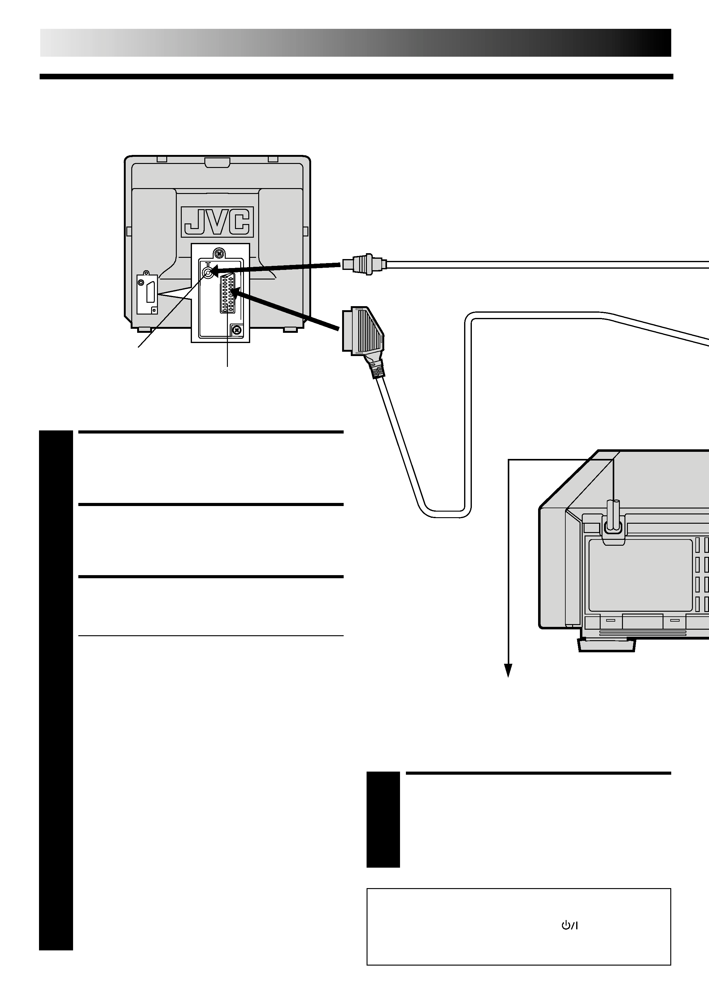
Basic Connections
CONNECT RECORDER TO
MAINS
4 Plugtheendofthemainspowercordintoamains
outlet.
21-pin AV input connector (SCART)
Aerial connector
It's essential that your video recorder be properly connected.
Follow these steps carefully. THESE STEPS MUST BE COMPLETED
BEFORE ANY VIDEO OPERATION CAN BE PERFORMED.
CHECK CONTENTS
1 Makesurethepackagecontainsalloftheaccessories
listed in "Specifications" (
pg. 63).
SITUATE RECORDER
2 Placetherecorderonastable,flatsurface.
CONNECT RECORDER TO TV
3 Theconnectionmethodyouusedependsonthetypeof
TV you have.
RF CONNECTION
To Connect To A TV With NO 21-pin AV input
connector (SCART) . . .
a Disconnect the TV aerial cable from the TV.
b Connect the TV aerial cable to the ANT. IN jack
on the rear panel of the recorder.
c Connect the provided RF cable between the RF
OUT jack on the rear panel of the recorder and the
TV's aerial connector.
Before operating the recorder, make sure the TV's
channel is set to the VIDEO channel (
pg. 10).
AV CONNECTION
To Connect To A TV with 21-pin AV input connector
(SCART) . . .
a Connect the aerial, recorder and TV as per "RF
CONNECTION".
b Connect an optional SCART cable between the AV1
IN/OUT connector on the rear panel of the recorder
and the TV's 21-pin AV input connector (SCART).
c Choose the appropriate AV1 output signal (
"AV1
OUTPUT SIGNAL SELECTION" on page 5).
S-VIDEO CONNECTION
If you have a TV with S-VIDEO input connector, see
"S-VIDEO Connection" on page 6.
Mains Power
Cord
Back of TV
21-pin SCART Cable (not provided)
Mains outlet
After you plug the mains power cord into a mains outlet, the
Auto Set Up display appears on the TV screen and/or on the
recorder's front display panel when the
button on the
recorder/remote control is pressed for the first time to power
on the recorder
pg. 8.
RF Cable (provided)
EN
5
AV1
OUT
COMP.
Y/C
AV1 IN/OUT
RF OUT
AV2 IN
PAUSE/
R.A.EDIT
ANT.IN
R
R
L
L
AUDIO
IN
OUT
S
IN
OUT
Back of Recorder
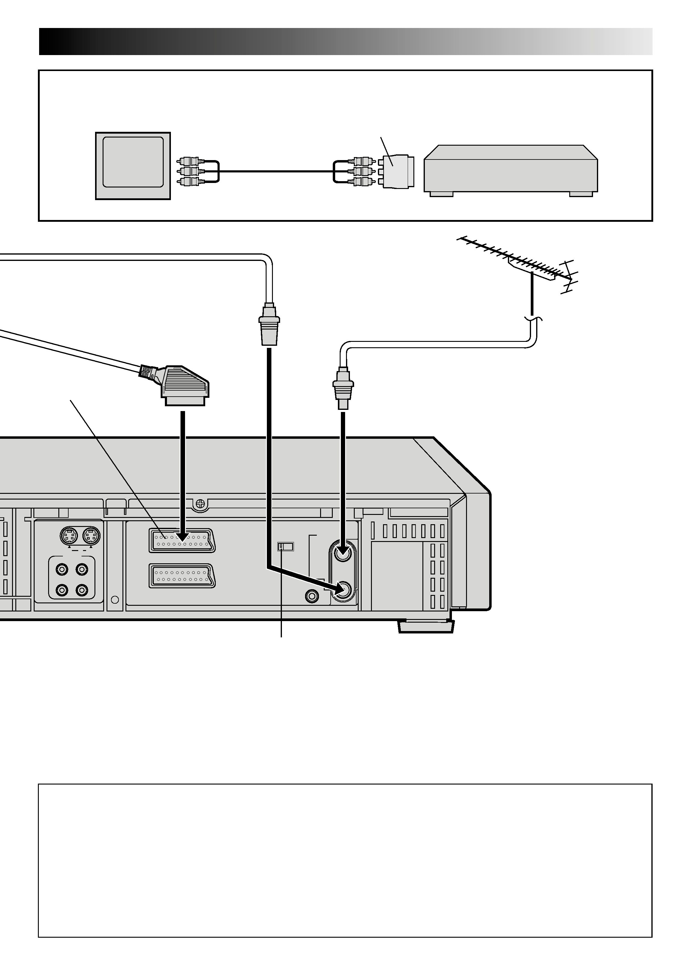
AV1 OUT Switch
To AV1 IN/OUT
connector
To AV-IN
terminals
Output cable adapter (not provided)
If TV has no 21-pin SCART connector:
Connect an optional AV cable between the TV's AV-IN terminals and the AV1 IN/OUT connector on the rear panel of the
recorder via the optional output cable adapter as illustrated.
AV cable
(not provided)
TV
Recorder
AV1 OUTPUT SIGNAL SELECTION
The AV1 IN/OUT connector accepts only a composite signal (regular video signal), but can deliver either a composite video
signal or a Y/C signal (a signal in which the luminance and chrominance signals are separated) according to the setting of the
rear panel AV1 OUT switch.
If your TV's 21-pin AV input connector (SCART) is compatible only with the regular video signal, set this switch to COMP.
If your TV's 21-pin AV input connector (SCART) is compatible with the Y/C signal, set this switch to Y/C. You will better enjoy
high-quality S-VHS pictures.
IMPORTANT:
Set your TV to the VIDEO (or AV), Y/C, or RGB mode according to the type of your TV's SCART connector.
For switching the TV's mode, refer to the instruction manual of your television.
AV1 IN/OUT
TV Aerial Cable (not provided)