No. 82930
July 2002
This service manual is printed on 100% recycled paper.
COPYRIGHT © 2002 VICTOR COMPANY OF JAPAN, LTD.
Regarding service information other than these sections, refer to the HR-S5900U service manual (No. 82848).
Also, be sure to note important safety precautions provided in the service manual.
HR-S8900KR
STOP
FIN
DATE
MENU
0000
DAILY/QTDN.
PROG
123
45
6
7
89
0
1
VCR / TV
VPS/PDC
OK
VCR
CABLE/
SAT/DVD
TV
2
4
EXPRESS
3
30 SEC
TV PR
TV PR +
+
TV
T
V
ENTER/EN
TREE
PR
WEEKLY/HEBDO
TV/VCR
MULTIMARQUE
START
DEBUT
AUDIO
AUX
VPS/PDC
VIDEO CASSETTE RECORDER
SERVICE MANUAL
=
W AC=NNM=V=J=OOM=V`I
SM=Hz
=
=
W NU=W
=
W QKM=W
!
WR
=QM
W JOM
=SM
=
W
=
=E
=ñ=
=ñ=
FW QMM=mm=ñ=VQ=mm=ñ
OSR=mm
W PKO=âÖ
W S-VHS/VHS NTSC=
=
=
SP
W STJONM=
=
!
ONM=
EP
W STJONM=
=
!
SPM=
LLLLL
=
W NTSCJ
=
=EIA
=
I=ROR=
L
SM=
L
=
=
W=DAJQ=E
Azimuth
F=
=
=
=
=
=
=
=
W QR=dB
=
VHS
W OPM=
S-VHS
W QMM=
=
=
W TM=Hz
=NMIMMM=Hz
Hi-Fi
=
W OM=Hz=
=OMIMMM=Hz
L
W RCA=
=E EINF=ñ
OI=
EOUTF=ñ=NF
S
J
=
=E
EINF=ñ=OI=
EOUTF=ñ
NF
=
W
J
=
=
=
VHF
W
=O=J=NP
UHF
W
=NQ=J=SV
CATV
W NNP=
RF
=
W
=P=
=Q=E
=
W=
= =
=P
=
F=TR=
=
W
!=
WN=
=
!"= =
=
LU=
!
=
=
W
=P=
=
W RF=
I
=
=
I
?AA?=
=ñ=OI
S
J
=
=EQ=J= F
=
!=
=
!=
=SP=
=
= =
K
E. & O.E
=
!=
!=
=
=
= =
!K
ITEM
MODEL
HR-S5900U
HR-S8900KR
!
REF
MODEL
HR-S5900U
HR-S8900KR
NO.
ITEM
TABLE OF CONTENTS
DIFFERENT TABLE .............................................................................................................................................................................................................. 1
3. ELECTRICAL ADJUSTMENT ........................................................................................................................................................................................ 3-1
Please see Service Manual No. 82848 (HR-S3900U/U(C), HR-S5900U/U(C)).
4. CHARTS AND DIAGRAMS (4-1 to 4-28)
4.1 BOARD INTERCONNECTIONS .................................................................................................................................................................................. 4-2
4.2 MAIN (VIDEO/AUDIO) SCHEMATIC DIAGRAM ......................................................................................................................................................... 4-4
4.3 MAIN (S-SUB) SCHEMATIC DIAGRAM ...................................................................................................................................................................... 4-6
4.4 MAIN (SYSCON) SCHEMATIC DIAGRAM .................................................................................................................................................................. 4-8
4.5 MAIN (SW. REG) SCHEMATIC DIAGRAM ................................................................................................................................................................ 4-10
4.6 MAIN (TUNER/DEMOD) SCHEMATIC DIAGRAM .................................................................................................................................................... 4-12
4.7 MAIN (FRONT) AND ADV. JOG SCHEMATIC DIAGRAMS ....................................................................................................................................... 4-14
4.8 MAIN (TERMINAL) SCHEMATIC DIAGRAM ............................................................................................................................................................. 4-16
4.9 MAIN (BS CONNECTION), S JACK, R. PAUSE AND MINI FRONT SCHEMATIC DIAGRAMS ................................................................................ 4-18
4.10 3D DIGITAL/2M SCHEMATIC DIAGRAM ............................................................................................................................................................... 4-20
4.11 DEMODULATOR SCHEMATIC DIAGRAM .............................................................................................................................................................. 4-22
4.12 MAIN AND R.PAUSE CIRCUIT BOARDS ............................................................................................................................................................... 4-24
4.13 3D/DIGITAL/2M AND DEMODULATOR CIRCUIT BOARDS ................................................................................................................................... 4-27
4.14 REMOTE CONTROL SCHEMATIC DIAGRAM ....................................................................................................................................................... 4-28
5. PARTS LIST (5-1 to 5-12)
5.1 PACKING AND ACCESSORY ASSEMBLY <M1> ....................................................................................................................................................... 5-1
5.2 FINAL ASSEMBLY <M2> ............................................................................................................................................................................................ 5-2
5.3 ELECTRICAL PARTS LIST ......................................................................................................................................................................................... 5-4
The following table indicate main different points between models HR-S5900U and HR-S8900KR.
MAIN BOARD ASSEMBLY <03>
The following table indicate different parts number between models HR-S5900U and HR-S8900KR.
PACKING AND ACCESSORY ASSEMBLY <M1>
PACKING AND ACCESSORY ASSEMBLY <M1> is indicated on the parts list.
FINAL ASSEMBLY <M2>
FINAL ASSEMBLY <M2> is indicated on the parts list.
Notes : Mark -- is not used.
PW1
MAIN BOARD ASSY
LPA10134-03D1
LPA10141-05A1
COSMETIC/COLOR
PAINT-BLACK
PURE SILVER
ILLUMI FUNCTION
GLOW
Not Used
HEAD CLEANER
Not Used
Used
TBC
Not Used
Used
F-1in(COLOR)
S,V,LR(SLV/BLACK) S,V,LR(Gld/Y,WR)
BACKUP TIME
--
3MIN
CHILD LOCK
Used
Not Used
POWER OFF DIMMER
Used
Not Used
!
REF
MODEL
HR-S5900U
HR-S8900KR
NO.
ITEM
2D DIGITAL BOARD ASSEMBLY <05>
PW1
2D DIGITAL BOARD ASSY LPA10090-05A
--
!
REF
MODEL
HR-S5900U
HR-S8900KR
NO.
ITEM
3D D/2M BOARD ASSEMBLY <05>
PW1
3D D/2M BOARD ASSY
--
LPA10105-02A
!
REF
MODEL
HR-S5900U
HR-S8900KR
NO.
ITEM
DEMOD BOARD ASSEMBLY <14>
PW1
DEMOD BOARD ASSY
PB11076A
LPA10094-06B
!
REF
MODEL
HR-S5900U
HR-S8900KR
NO.
ITEM
MINI FRONT BOARD ASSEMBLY <28>
PW1
MINI FRONT BOARD ASSY
--
LPA20014-01A
!
REF
MODEL
HR-S5900U
HR-S8900KR
NO.
ITEM
S JACK BOARD ASSEMBLY <36>
PW1
S JACK BOARD ASSY
LPA20009-02B
LPA20009-01B
J7102 S JACK
QND0084-001
QND0085-001
!
REF
MODEL
HR-S5900U
HR-S8900KR
NO.
ITEM
ADV.JOG BOARD ASSEMBLY <38>
PW1
ADV.JOG BOARD ASSY
LPA20013-04B
LPA20013-03B
!
REF
MODEL
HR-S5900U
HR-S8900KR
NO.
ITEM
R.PAUSE BOARD ASSEMBLY <91>
PW2
R.PAUSE BOARD ASSY
LPA10134-03C2
LPA10141-01B2
!
REF
MODEL
HR-S5900U
HR-S8900KR
NO.
ITEM
C.BOX BOARD ASSEMBLY <92>
PW3
C.BOX BOARD ASSY
LPA10134-03C3
--
1
3-1
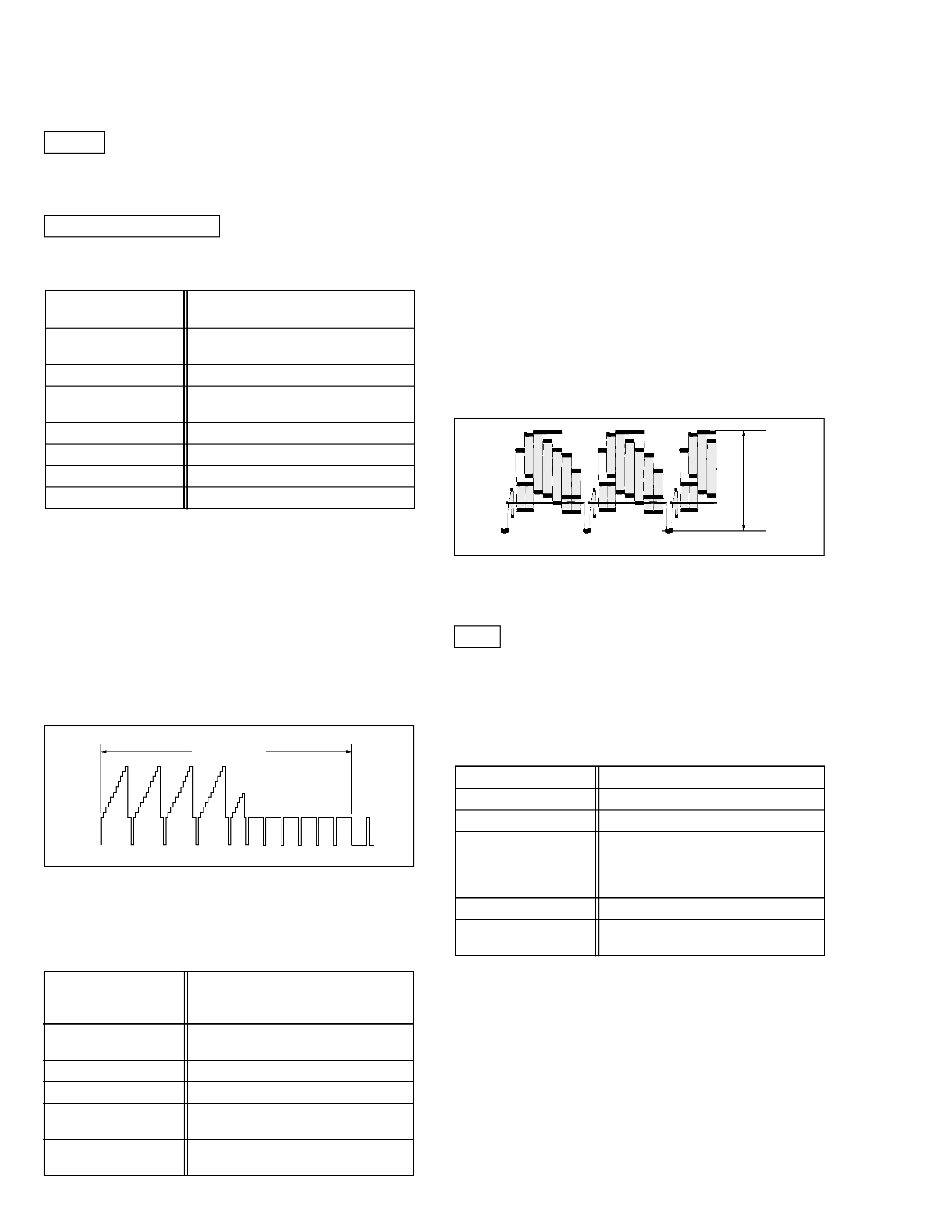
3.2 SERVO CIRCUIT
3.2.1 Switching point
Signal
(A1)
· Stairstep signal
(A2)
· Alignment tape(SP, stairstep, NTSC) [MHP]
Mode
(B)
· PB
· TBC: OFF
Equipment
(C)
· Oscilloscope
Measuring point
(D1)
· VIDEO OUT terminal (75Ø terminated)
(D2)
· TP106 (PB. FM)
External trigger
(E)
· TP111 (D.FF)/slope :
Adjustment part
(F)
· Jig RCU: Code "51" or "52"
Specified value
(G)
· 8.0 ± 0.5H
Adjustment tool
(H)
· Jig RCU [PTU94023B]
(1) Play back the signal (A1) of the alignment tape (A2).
(2) Apply the external trigger signal to D.FF (E) to observe
the VIDEO OUT waveform and V.PB FM waveform at the
measuring points (D1) and (D2).
(3) Set the VCR to the manual tracking mode.
(4) Adjust tracking so that the V.PB FM waveform becomes
maximum.
(5) Transmit the code (F) from the Jig RCU to adjust so that
the trigger point of the VIDEO OUT waveform is changed
from the trailing edge of the V.sync signal becomes the
specified value (G).
(6) Set the VCR to the stop mode or eject mode.
Fig. 3-2-1a
Switching point
V.sync
Trigger point
Switching point
V. rate
SECTION 3
ELECTRICAL ADJUSTMENT
Please see Service Manual No. 82848 (HR-S3900U/U(C), HR-S5900U/U(C)).
As for the following items, adjustment is not required or the adjustment has been changed in this model as follows.
Delete
3.5 DEMODULATOR CIRCUIT
Adjustment is changing
Fig. 3-3-1a
D/A level
(1) Insert the cassette tape (A3) to enter the mode (B).
(2) Observe the VIDEO OUT waveform at the measuring
point (D).
(3) Check the Y level value when the External S-input (Y/C
separated video signal).
(4) Switch the input signal to the External input (composite
video signal), and adjust the adjustment part (F) so that
the Y level becomes the same value observed in step
(3).
Note:
· The specified value (G) is just a reference value to be
obtained when the External S-Video (Y/C separated
video) signal is input. In actual adjustment, set it to
the value observed in step (3).
H. rate
Y level
3.3 VIDEO CIRCUIT
3.3.1 D/A level
Signal
(A1)
· Ext. S-input / Ext. input
(A2)
· Color (colour) bar signal [NTSC]
(A3)
· S-VHS tape
Mode
(B)
· S-VHS
· EE
Equipment
(C)
· Oscilloscope
Measuring point
(D)
· VIDEO OUT terminal (75Ø terminated)
Adjustment part
(F)
· VR1401 (D/A LEVEL ADJ)
[3D DIGITAL/2M board]
Specified value
(G)
· 1.00 ± 0.015 Vp-p (reference value)
(Note)
Add
3.6
Syscon circuit
Note:
·
When perform this adjustment, remove the Mechanism
assembly.
3.6.1 Timer clock
Signal
(A)
· No signal
Mode
(B)
· EE
Equipment
(C)
· Frequency counter
Measuring point (D1)
· IC3001 pin29
Short point
(D2)
· IC3001 pin56
(D3)
· IC3001 pin57
(D4)
· IC3001 pin25
Adjustment part
(F)
· C3018 (TIMER CLOCK)
Specified value
(G)
· 1024.008
± 0.001 Hz
(976.554
± 0.001 µsec)
(1) Connect the frequency counter to the measuring point (D1).
(2) Connect the short wire between the short point (D2) and GND.
(3) Connect the short wire between the short point (D3) and GND.
(4) Connect the short wire between the short point (D4) and GND
in order to reset the microprocessor of the SYSCON.
(5) Disconnect the short wire of step (3).
(6) Adjust the Adjustment part (F) so that the output fre-
quency becomes the specified value (G).

Printed in Japan
0207WPC
VICTOR COMPANY OF JAPAN, LIMITED
HOME AV NETWORK BUSINESS UNIT
12, 3-chome, Moriya-cho, kanagawa-ku, Yokohama, kanagawa-prefecture, 221-8528, Japan