SERVICE MANUAL
No. 82824
September 2000
HR-S8700MS/S9700MS
CARACTÉRISTIQUES TECHNIQUES (The specifications shown pertain specifically to the model HR-S9700MS)
MAGNETOSCOPE
Printed in Japan
VICTOR COMPANY OF JAPAN, LIMITED
VIDEO DIVISION
S40894
This service manual is printed on 100% recycled paper.
COPYRIGHT © 2000 VICTOR COMPANY OF JAPAN, LTD.
HR-S8700MS/S9700MS
No.
82824
GÉNÉRALES
Alimentation
: CA 220 V 240 V ` , 50 Hz/60 Hz
Consommation
Alimentation en marche : 27 W
Alimentation en veille
: 5,2 W
Températures
Fonctionnement
: 5°C à 40°C
Stockage
: -20°C à 60°C
Position de fonctionnement
: Seulement horizontale
Dimensions (LxHxP)
: 437 mm x 106 mm x 352 mm
Poids
: 5,2 kg
Format
: Standard S-VHS/VHS PAL/SECAM
Largeur de bande
: 12,65 mm
Vitesse de bande
(VN)
: 23,39 mm/s
(LD)
: 11,70 mm/s
(EP)*
: 7,80 mm/s
Durée maximale d'enregistrement
(VN)
: 240 mn avec une cassette vidéo E-240
(LD)
: 480 mn avec une cassette vidéo E-240
(EP)*
: 720 mn avec une cassette vidéo E-240
*
Signaux PAL seulement
VIDÉO/AUDIO
Système de signal
: Signaux couleur PAL/SECAM et signal
monochrome CCIR, 625 lignes/50 trames
Système d'enregistrement : Balayage hélicoïdal DA4 (Double Azimuth)
Entrée
: 0,5 Vcc à 2,0 Vcc, 75 ohms, asymétrique
Sortie
: 1,0 Vcc, 75 ohms, asymétrique
Rapport signal/bruit
: 45 dB
Résolution horizontale : 400 lignes (S-VHS-PAL, VN/LD)
250 lignes (VHS-PAL, VN/LD)
350 lignes (S-VHS-PAL, EP)
220 lignes (VHS-PAL, EP)
240 lignes (VHS-SECAM, VN/LD)
Gamme de fréquence
: 70 Hz à 10.000 Hz (Audio normal)
20 Hz à 20.000 Hz (Audio Hi-Fi)
Entrée/sortie
: Connecteurs péritélévision à 21 broches:
ENTREE/SORTIE x 1, ENTREE/DECODEUR x 1
Connecteurs RCA: ENTREE VIDEO x 1,
ENTREE AUDIO x 1, SORTIE AUDIO x 1
Connecteurs S-Vidéo: ENTREE x 1, SORTIE x 1
SYNTONISEUR
Système de syntonisation
: Syntoniseur à synthèse de fréquence
Capacité de canaux TV
: 99 positions (+ position AUX)
Canaux couverts
MINUTERIE
Référence de l'horloge
: Par quartz
Capacité de programmation : Minuterie sur 1 an/8 programmes
Durée de soutien mémoire : 60 mn
ACCESSOIRES
Accessoires fournis
: Câble RF,
Câble S-Vidéo,
Câble péritélévision à 21 broches,
Adaptateur antenne,
Contrôleur satellite RM-SD1,
Boîtier de télécommande à infrarouge,
Pile "R6" x 2,
Etiquettes S-VHS ET
ATTENTION:
Ce magnétoscope contient des microprocesseurs. Des bruits électroniques
externes ou des interférences peuvent causer un mauvais fonctionnement.
Dans de tels cas, couper l'alimentation et débrancher le cordon
d'alimentation. Puis le rebrancher et remettre l'alimentation. Sortir la cassette.
Après contrôle de la cassette, faire fonctionner l'appareil comme d'ordinaire.
Les caractéristiques techniques sont pour le mode VN à moins
d'indication contraire.
Présentation et caractéristiques modifiables sans préavis.
Gamme
SECAM L
PAL B/G
Fréquence
Canaux
Fréquence
Canaux
VHF
49 MHz 65 MHz 2 4
47 MHz 89 MHz E2 E4
(LOW)
X, Y, Z
E5 E12
VHF
104 MHz
5 10
104 MHz
S1 S20
(HIGH)
300 MHz
CATV
300 MHz
M1 M10
U1 U10
Hyper
300 MHz 470 MHz CATV
302 MHz 470 MHz S21 S41
UHF
470 MHz 862 MHz 21 69 470 MHz 862 MHz E21 E69

Important Safety Precautions
INSTRUCTIONS
1. DISASSEMBLY
1.1 DISASSEMBLY FLOW CHART ............................................................ 1-1
1.2 HOW TO READ THE DISASSEMBLY AND ASSEMBLY ...................... 1-1
1.3 DISASSEMBLY/ASSEMBLY METHOD ................................................ 1-1
1.4 SERVICE POSITION ............................................................................ 1-5
1.4.1 How to take out the Mechanism and Main board assemblies
[HR-S9700MS] ................................................................................ 1-5
1.4.2 How to take out the Mechanism and Main board assemblies
[HR-S8700MS] ................................................................................ 1-6
1.4.3 Precautions for cassette loading in the "SERVICE POSITION" ..... 1-6
1.4.4 Cassette loading and ejection methods in the "SERVICE
POSITION"(See Fig. 1-4-3 or Fig. 1-4-4.) ....................................... 1-6
1.5 MECHANISM SERVICE MODE ........................................................... 1-6
1.6 EMERGENCY DISPLAY FUNCTION ................................................... 1-8
1.6.1 Displaying the emergency information ............................................ 1-8
1.6.2 Clearing the emergency history ...................................................... 1-8
1.6.3 Emergency content description ...................................................... 1-9
1.6.4 Emergency detail information 1 ................................................... 1-10
1.6.5 Emergency detail information 2 ................................................... 1-11
1.7 SERVICING THE VIDEO NAVIGATION FUNCTION ......................... 1-12
1.7.1 Copying the video navigation data ................................................ 1-12
1.7.2 Erasing the video navigation data (Initialization) .......................... 1-13
1.7.3 Factory setting level during shipment ........................................... 1-13
2. MECHANISM ADJUSTMENT
2.1 BEFORE STARTING REPAIR AND ADJUSTMENT ............................ 2-1
2.1.1 Precautions ..................................................................................... 2-1
2.1.2 Checking for Proper Mechanical Operations .................................. 2-1
2.1.3 Manually Removing the Cassette Tape .......................................... 2-1
2.1.4 Jigs and Tools Required for Adjustment .......................................... 2-2
2.1.5 Maintenance and Inspection ........................................................... 2-3
2.2 REPLACEMENT OF MAJOR PARTS .................................................. 2-6
2.2.1 Before Starting Disassembling (Phase matching between
mechanical parts) ........................................................................... 2-6
2.2.2 How to Set the Mechanism Assembling Mode ............................... 2-6
2.2.3 Cassette Holder Assembly .............................................................. 2-6
2.2.4 Pinch Roller Arm Assembly ............................................................. 2-8
2.2.5 Guide Arm Assembly and Press Lever Assembly ........................... 2-8
2.2.6 Audio Control Head ........................................................................ 2-8
2.2.7 Loading Motor ................................................................................. 2-8
2.2.8 Capstan Motor ................................................................................ 2-9
2.2.9 Pole Base Assembly (supply or take-up side) ................................ 2-9
2.2.10 Rotary Encoder ........................................................................... 2-10
2.2.11 Clutch Unit .................................................................................. 2-10
2.2.12 Change Lever Assembly, Direct Gear, Clutch Gear and Coupling Gear 2-10
2.2.13 Link Lever ................................................................................... 2-11
2.2.14 Cassette Gear, Control Cam and Worm Gear ............................ 2-11
2.2.15 Control Plate ............................................................................... 2-11
2.2.16 Loading Arm Gear (supply or take-up side) and Loading Arm Gear Shaft 2-12
2.2.17 Take-up Lever, Take-up Head and Control Plate Guide ............. 2-13
2.2.18 Capstan Brake Assembly ........................................................... 2-13
2.2.19 Sub Brake Assembly (take-up side) ........................................... 2-13
2.2.20 Main Brake Assembly (take-up side), Reel Disk (take-up side) and
Main Brake Assembly (supply side) ................................................ 2-13
2.2.21 Tension Brake Assembly, Reel Disk (supply side) and
Tension Arm Assembly ............................................................... 2-14
2.2.22 Idler Lever, Idler Arm Assembly .................................................. 2-14
2.2.23 Stator Assembly .......................................................................... 2-14
2.2.24 Rotor Assembly .......................................................................... 2-14
2.2.25 Upper Drum Assembly ................................................................ 2-15
2.3 COMPATIBILITY ADJUSTMENT ........................................................ 2-16
2.3.1 Checking/Adjustment of FM Waveform Linearity .......................... 2-16
2.3.2 Checking/Adjustment of the Height and Tilt of the Audio Control Head 2-17
2.3.3 Checking/Adjustment of the Audio Control Head Phase (X-Value)2-17
2.3.4 Checking/Adjustment of the Standard Tracking Preset ................ 2-18
2.3.5 Checking/Adjustment of the Tension Pole Position....................... 2-18
3. ELECTRICAL ADJUSTMENT
3.1 PRECAUTION ..................................................................................... 3-1
3.1.1 Required test equipments ............................................................... 3-1
3.1.2 Required adjustment tools .............................................................. 3-1
3.1.3 Color (colour) bar signal,Color (colour) bar pattern ........................ 3-1
3.1.4 Switch settings and standard precautions ...................................... 3-1
3.1.5 EVR Adjustment .............................................................................. 3-1
3.2 SERVO CIRCUIT .................................................................................. 3-2
3.2.1 Switching point ................................................................................ 3-2
3.2.2 Slow tracking preset ....................................................................... 3-2
3.2.3 Dynamic Drum preset [HR-S9700MS] ............................................ 3-2
TABLE OF CONTENTS
Section
Title
Page
Section
Title
Page
HR-S8700MS
HR-S9700MS
TIME SCAN(DD)/X1.5(DD)/PRO.SLOW(DD)
NOT USED
USED
VIDEO SYSTEM
SECAM/PAL CONVERTER
SECAM/PAL CONVERTER
PAL/SECAM CONVERTER
SLOWMOTION (FWD/REV)
±1/6, ±1/18
±1/6(EP), ±1/18(EP)
PRO±1/2(SP/LP), PRO±1/3(SP)
SHUTTLE SEARCH
SP, LP, EP : X15
SP Ú ±15, LP/EP : 15, +13
FIGH GRADE AUDIO PARTS
NOT USED
USED
TAPE ACCESS (MARK/ERASE)
AUTO/NOT USED
AUTO & MANUAL/MANUAL
TAPE ACCESS (R.A.EDIT / w / SOUND SHUTTLE)
NOT USED
USED
The following table lists the differing points between Models (HR-S8700MS and HR-S9700MS) in this series.
3.3 VIDEO CIRCUIT ................................................................................... 3-3
3.3.1 D/A level .......................................................................................... 3-3
3.3.2 EE Y level ....................................................................................... 3-3
3.3.3 PB Y level (S-VHS / VHS) ............................................................... 3-3
3.3.4 REC color (colour) level .................................................................. 3-4
3.3.5 Video EQ (Frequency response) .................................................... 3-4
3.3.6 AUTO PICTURE initial setting ........................................................ 3-5
3.4 AUDIO CIRCUIT ................................................................................... 3-5
3.4.1 Audio REC FM ................................................................................ 3-5
3.5 PAL/SECAM CONVERTER CIRCUIT .................................................. 3-5
3.5.1 fH VCO ........................................................................................... 3-5
3.5.2 DEMOD Fo ..................................................................................... 3-5
3.5.3 Colour difference level .................................................................... 3-6
3.5.4 PAL burst position ........................................................................... 3-6
3.5.5 SECAM BELL [HR-S9700MS] ........................................................ 3-6
4. CHARTS AND DIAGRAMS
NOTES OF SCHEMATIC DIAGRAM .......................................................... 4-1
CIRCUIT BOARD NOTES ........................................................................... 4-2
4.1 BOARD INTERCONNECTIONS .......................................................... 4-3
4.2 VIDEO/AUDIO AND AUDIO ERASE SCHEMATIC DIAGRAMS................ 4-5
4.3 VSC SCHEMATIC DIAGRAM [HR-S9700MS] ..................................... 4-7
4.4 SYSTEM CONTROL SCHEMATIC DIAGRAM .................................... 4-9
4.5 SWITCHING REGULATOR SCHEMATIC DIAGRAM ....................... 4-11
4.6 TUNER SCHEMATIC DIAGRAM ....................................................... 4-13
4.7 CONNECTION SCHEMATIC DIAGRAM ........................................... 4-15
4.8 3D DIGITAL/2M SCHEMATIC DIAGRAM .......................................... 4-17
4.9 TERMINAL SCHEMATIC DIAGRAM ................................................. 4-19
4.10 DEMODULATOR SCHEMATIC DIAGRAM ..................................... 4-21
4.11 S-SUB SCHEMATIC DIAGRAM ...................................................... 4-23
4.12 NAVIGATION SCHEMATIC DIAGRAM ........................................... 4-25
4.13 NAVIGATION SCHEMATIC DIAGRAM ........................................... 4-27
4.14 SW/DISPLAY, REC SAFETY, JACK AND JOG SCHEMATIC DIAGRAMS [HR-S8700MS] 4-29
4.15 SW/DISPLAY AND REC SAFETY SCHEMATIC DIAGRAMS [HR-S9700MS] 4-31
4.16 P/S CONVERTER SCHEMATIC DIAGRAM [HR-S8700MS] ................ 4-33
4.17 P/S CONVERTER SCHEMATIC DIAGRAM [HR-S9700MS] ................ 4-35
4.18 SECAM SCHEMATIC DIAGRAM ..................................................... 4-37
4.19 3D DIGITAL/2M AND S-SUB CIRCUIT BOARDS ........................... 4-39
4.20 TERMINAL CIRCUIT BOARD .......................................................... 4-40
4.21 MAIN, A/C HEAD, AUDIO ERASE AND LOADING MOTOR
CIRCUIT BOARDS ........................................................................... 4-41
4.22 NAVIGATION CIRCUIT BOARD ...................................................... 4-44
4.23 SW/DISPLAY, REC SAFETY, JACK AND JOG
CIRCUIT BOARDS ........................................................................... 4-45
4.24 P/S CONVERTER CIRCUIT BOARD .............................................. 4-47
4.25 DEMODULATOR AND SECAM CIRCUIT BOARDS ....................... 4-49
4.26 FDP GRID ASSIGNMENT AND ANODE CONNECTION ..................... 4-50
4.27 REMOTE CONTROL AND MEMBRANE DOOR SCHEMATIC DIAGRAMS ................... 4-51
4.28 WAVEFORMS .................................................................................. 4-52
4.29 VOLTAGE CHARTS ......................................................................... 4-55
4.30 CPU PIN FUNCTION ....................................................................... 4-57
4.31 SYSTEM CONTROL BLOCK DIAGRAM ......................................... 4-59
4.32 VIDEO BLOCK DIAGRAM ............................................................... 4-61
4.33 AUDIO BLOCK DIAGRAM ............................................................... 4-65
5. PARTS LIST
5.1 PACKING AND ACCESSORY ASSEMBLY <M1> ............................... 5-1
5.2 CABINET AND CHASSIS ASSEMBLY <M2> ...................................... 5-2
5.3 MECHANISM ASSEMBLY <M4> ......................................................... 5-4
5.4 ELECTRICAL PARTS LIST .................................................................. 5-6
MAIN BOARD ASSEMBLY <03> .............................................................. 5-6
3D DIGITAL/2M BOARD ASSEMBLY <05> ............................................ 5-13
TERMINAL BOARD ASSEMBLY <06> ................................................... 5-15
AUDIO CONTROL HEAD BOARD ASSEMBLY <12> ............................ 5-16
DEMOD BOARD ASSEMBLY <14> ........................................................ 5-16
S-SUB BOARD ASSEMBLY <15> .......................................................... 5-17
NAVIGATION BOARD ASSEMBLY <19>
[LPB10108-001*] (HR-S8700MS/S9700MS) .......................................... 5-18
NAVIGATION BOARD ASSEMBLY <19>
[LPB10108-002*] (HR-S9700MS) ........................................................... 5-18
DISPLAY BOARD ASSEMBLY(S8700MS) <28> .................................... 5-19
DISPLAY BOARD ASSEMBLY(S9700MS) <28> .................................... 5-20
REC SAFETY BOARD ASSEMBLY(S9700MS)<32> ............................. 5-21
REC SAFETY BOARD ASSEMBLY(S8700MS) <32> ............................ 5-21
S JACK BOARD ASSEMBLY (S8700MS) <36> ..................................... 5-21
JOG BOARD ASSEMBLY (S8700MS) <37> ........................................... 5-21
AUDIO ERASE BOARD ASSEMBLY <46> ............................................. 5-21
LOADING MOTOR BOARD ASSEMBLY <55> ....................................... 5-21
P/S CONVERTER BOARD ASSEMBLY <87> ........................................ 5-21
SECAM BOARD ASSEMBLY <88> ........................................................ 5-24
Important Safety Precautions
Prior to shipment from the factory, JVC products are strictly inspected to conform with the recognized product safety and electrical codes of the
countries in which they are to be sold. However, in order to maintain such compliance, it is equally important to implement the following precautions
when a set is being serviced.
Fig.1
1. Locations requiring special caution are denoted by labels and in-
scriptions on the cabinet, chassis and certain parts of the product.
When performing service, be sure to read and comply with these
and other cautionary notices appearing in the operation and serv-
ice manuals.
2. Parts identified by the
symbol and shaded (
) parts are
critical for safety.
Replace only with specified part numbers.
Note: Parts in this category also include those specified to com-
ply with X-ray emission standards for products using
cathode ray tubes and those specified for compliance
with various regulations regarding spurious radiation
emission.
3. Fuse replacement caution notice.
Caution for continued protection against fire hazard.
Replace only with same type and rated fuse(s) as specified.
4. Use specified internal wiring. Note especially:
1) Wires covered with PVC tubing
2) Double insulated wires
3) High voltage leads
5. Use specified insulating materials for hazardous live parts. Note
especially:
1) Insulation Tape
3) Spacers
5) Barrier
2) PVC tubing
4) Insulation sheets for transistors
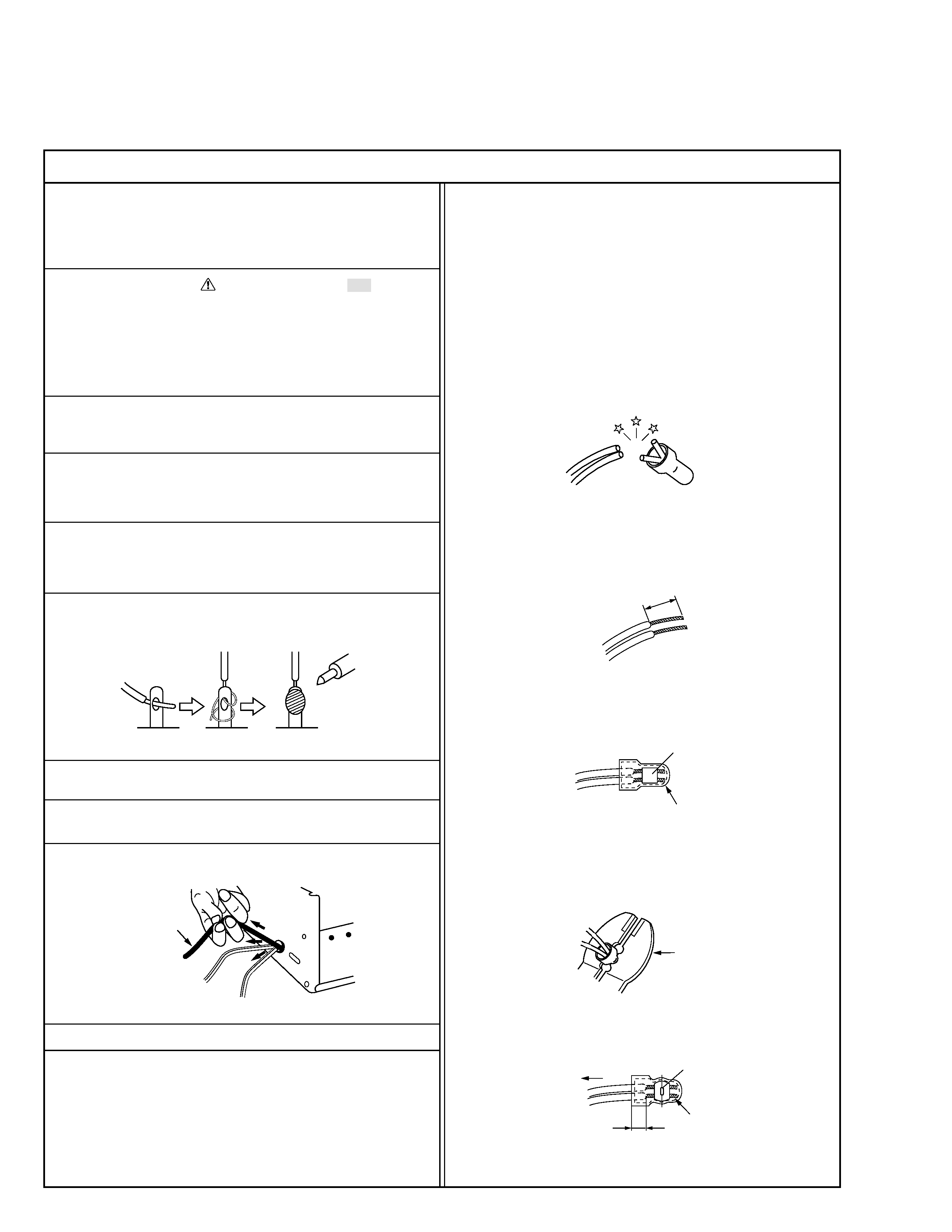
6. When replacing AC primary side components (transformers, power
cords, noise blocking capacitors, etc.) wrap ends of wires securely
about the terminals before soldering.
Power cord
Fig.2
10. Also check areas surrounding repaired locations.
11. Products using cathode ray tubes (CRTs)
In regard to such products, the cathode ray tubes themselves, the
high voltage circuits, and related circuits are specified for compli-
ance with recognized codes pertaining to X-ray emission.
Consequently, when servicing these products, replace the cath-
ode ray tubes and other parts with only the specified parts. Under
no circumstances attempt to modify these circuits.
Unauthorized modification can increase the high voltage value and
cause X-ray emission from the cathode ray tube.
12. Crimp type wire connector
In such cases as when replacing the power transformer in sets
where the connections between the power cord and power trans-
former primary lead wires are performed using crimp type connec-
tors, if replacing the connectors is unavoidable, in order to prevent
safety hazards, perform carefully and precisely according to the
following steps.
1) Connector part number : E03830-001
2) Required tool : Connector crimping tool of the proper type which
will not damage insulated parts.
3) Replacement procedure
(1) Remove the old connector by cutting the wires at a point
close to the connector.
Important : Do not reuse a connector (discard it).
Fig.7
cut close to connector
Fig.3
(2) Strip about 15 mm of the insulation from the ends of the
wires. If the wires are stranded, twist the strands to avoid
frayed conductors.
15 mm
Fig.4
(3) Align the lengths of the wires to be connected. Insert the
wires fully into the connector.
Connector
Metal sleeve
Fig.5
(4) As shown in Fig.6, use the crimping tool to crimp the metal
sleeve at the center position. Be sure to crimp fully to the
complete closure of the tool.
1
·Precautions during Servicing
7. Observe that wires do not contact heat producing parts (heatsinks,
oxide metal film resistors, fusible resistors, etc.)
8. Check that replaced wires do not contact sharp edged or pointed
parts.
9. When a power cord has been replaced, check that 10-15 kg of
force in any direction will not loosen it.
1.2
5
2.0
5.5
Crimping tool
Fig.6
(5) Check the four points noted in Fig.7.
Not easily pulled free
Crimped at approx. center
of metal sleeve
Conductors extended
Wire insulation recessed
more than 4 mm
S40888-01
·Safety Check after Servicing
Examine the area surrounding the repaired location for damage or deterioration. Observe that screws, parts and wires have been returned
to original positions, Afterwards, perform the following tests and confirm the specified values in order to verify compliance with safety
standards.
1. Insulation resistance test
Confirm the specified insulation resistance or greater between power cord plug prongs and exter-
nally exposed parts of the set (RF terminals, antenna terminals, video and audio input and output
terminals, microphone jacks, earphone jacks, etc.). See table 1 below.
2. Dielectric strength test
Confirm specified dielectric strength or greater between power cord plug prongs and exposed acces-
sible parts of the set (RF terminals, antenna terminals, video and audio input and output terminals,
microphone jacks, earphone jacks, etc.). See table 1 below.
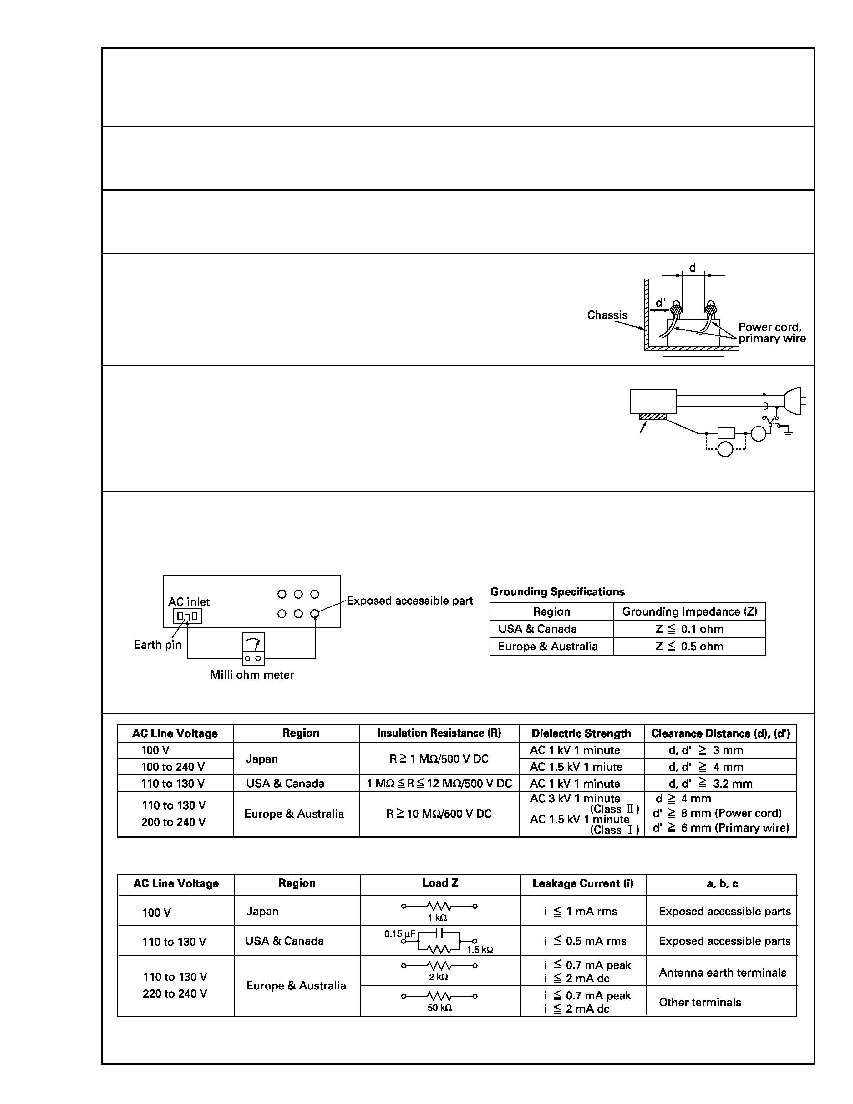
3. Clearance distance
When replacing primary circuit components, confirm specified clearance distance (d), (d') be-
tween soldered terminals, and between terminals and surrounding metallic parts. See table 1
below.
4. Leakage current test
Confirm specified or lower leakage current between earth ground/power cord plug prongs and
externally exposed accessible parts (RF terminals, antenna terminals, video and audio input and
output terminals, microphone jacks, earphone jacks, etc.).
Measuring Method : (Power ON)
Insert load Z between earth ground/power cord plug prongs and externally exposed accessible
parts. Use an AC voltmeter to measure across both terminals of load Z. See figure 9 and following
table 2.
5. Grounding (Class 1 model only)
Confirm specified or lower grounding impedance between earth pin in AC inlet and externally exposed accessible parts (Video in, Video out,
Audio in, Audio out or Fixing screw etc.).
Measuring Method:
Connect milli ohm meter between earth pin in AC inlet and exposed accessible parts. See figure 10 and grounding specifications.
Fig. 10
Fig. 9
Fig. 8
Table 1 Specifications for each region
Table 2 Leakage current specifications for each region
Note: These tables are unofficial and for reference only. Be sure to confirm the precise values for your particular country and locality.
2
S40888-01
ab
c
V
A
Externally
exposed
accessible part
Z
