COPYRIGHT © 2003 VICTOR COMPANY OF JAPAN, LTD
SERVICE MANUAL
Regarding service information other than these sections, refer to the service manual No. 82957 (HR-S8960EX).
Also, be sure to note important safety precautions provided in the service manual.
GENERAL
Power requirement : AC 220 V 240 Vd, 50 Hz/60 Hz
Power consumption
Power on
: 18 W
Power off
: 3.3 W
Temperature
Operating
: 5
°C to 40°C
Storage
: 20
°C to 60°C
Operating position : Horizontal only
Dimensions (WxHxD)
: 400 mm x 94 mm x 270 mm
Weight
: 3.3 kg
Format
: S-VHS/VHS PAL standard
Maximum recording time
(SP)
: 240 min. with E-240 video cassette
(LP)
: 480 min. with E-240 video cassette
(EP)
: 720 min. with E-240 video cassette
VIDEO/AUDIO
Signal system
: PAL-type colour signal and CCIR
monochrome signal, 625 lines
50 fields
Recording system
: DA4 (Double Azimuth) head helical
scan system
Signal-to-noise ratio : 45 dB
Horizontal resolution
(SP/LP)
: 250 lines (VHS)
400 lines (S-VHS)
(EP)
: 220 lines (VHS)
350 lines (S-VHS)
Frequency range
: 70 Hz to 10,000 Hz (Normal audio)
20 Hz to 20,000 Hz (Hi-Fi audio)
Input/Output
: 21-pin SCART connectors:
IN/OUT x 1, IN/DECODER x 1
RCA connectors:
VIDEO IN x 1, AUDIO IN x 1,
AUDIO OUT x 1
S-Video connector:
IN x 1, OUT x 1
TUNER/TIMER
TV channel storage capacity
: 99 positions (+AUX position)
Tuning system
: Frequency synthesized tuner
Channel coverage
: VHF 47 MHz 89 MHz/
104 MHz 300 MHz/
302 MHz 470 MHz
UHF 470 MHz 862 MHz
Aerial output
: UHF channels 22 69 (Adjustable)
Memory backup time
: Approx. 10 min.
ACCESSORIES
Provided accessories
: RF cable,
Infrared remote control unit,
"R6" battery x 2
Specifications shown are for SP mode unless otherwise
specified.
E.& O.E. Design and specifications subject to change without
notice.
No.82975
2003/07
HR-S7960EX, HR-S7965EF,
HR-S7965EK
HR-S7960EX, HR-S7965EF, HR-S7965EK V16S2
VIDEO CASSETTE RECORDER
SPECIFICATIONS (The specifications shown pertain specifically to the model HR-S7960EX.)
CONTENTS
DIFFERENT LIST ................................................................................................................................................................................................... 1 only
3.
ADJUSTMENT
3.1 Electrical adjustment .......................................................................................................................................................................................... 3-1
3.1.1 PAL/SECAM converter circuit[EF MODEL] ..................................................................................................................................................... 3-1
3.1.1.1 Colour difference level .................................................................................................................................................................................. 3-1
3.1.1.2 SECAM burst position ................................................................................................................................................................................... 3-1
4.
CHARTS AND DIAGRAMS
4.1 S-P CONVERTER SCHEMATIC DIAGRAM [EF MODEL] ................................................................................................................................ 4-1
4.2 MAIN(SECAM) SCHEMATIC DIAGRAM [EF MODEL] ....................................................................................................................................... 4-3
4.3 S-P CONVERTER CIRCUIT BOARD [EF MODEL] ........................................................................................................................................... 4-4
5.
PARTS LIST ....................................................................................................................................................................................................... 5-1
5.1 EXPLODED VIEW ............................................................................................................................................................................................. 5-1
5.2 PARTS LIST ....................................................................................................................................................................................................... 5-4
PACKING AND ACCESSORY ASSEMBLY<M1> .................................................................................................................................................. 5-4
FINAL ASSEMBLY<M2> ........................................................................................................................................................................................ 5-4
MECHANISM ASSEMBLY<M4> ............................................................................................................................................................................ 5-4
MAIN BOARD ASSEMBLY<03> ............................................................................................................................................................................ 5-5
3D DIGITAL/2M BOARD ASSEMBLY<05> .......................................................................................................................................................... 5-13
TERMINAL BOARD ASSEMBLY<06> ................................................................................................................................................................. 5-14
A/C HEAD BOARD ASSEMBLY<12> .................................................................................................................................................................. 5-16
DEMOD BOARD ASSEMBLY<14> ...................................................................................................................................................................... 5-16
S JACK BOARD ASSEMBLY<36> ....................................................................................................................................................................... 5-16
ADV. JOG BOARD ASSEMBLY<39> ................................................................................................................................................................... 5-17
LOADING MOTOR BOARD ASSEMBLY<55> ..................................................................................................................................................... 5-17
S-P CONV. BOARD ASSEMBLY<87> [FOR HR-S7965EF] ................................................................................................................................ 5-17
The following table indicate main different points between models HR-S8960EX, HR-S7960EX, HR-S7965EF and HR-
S7965EK.
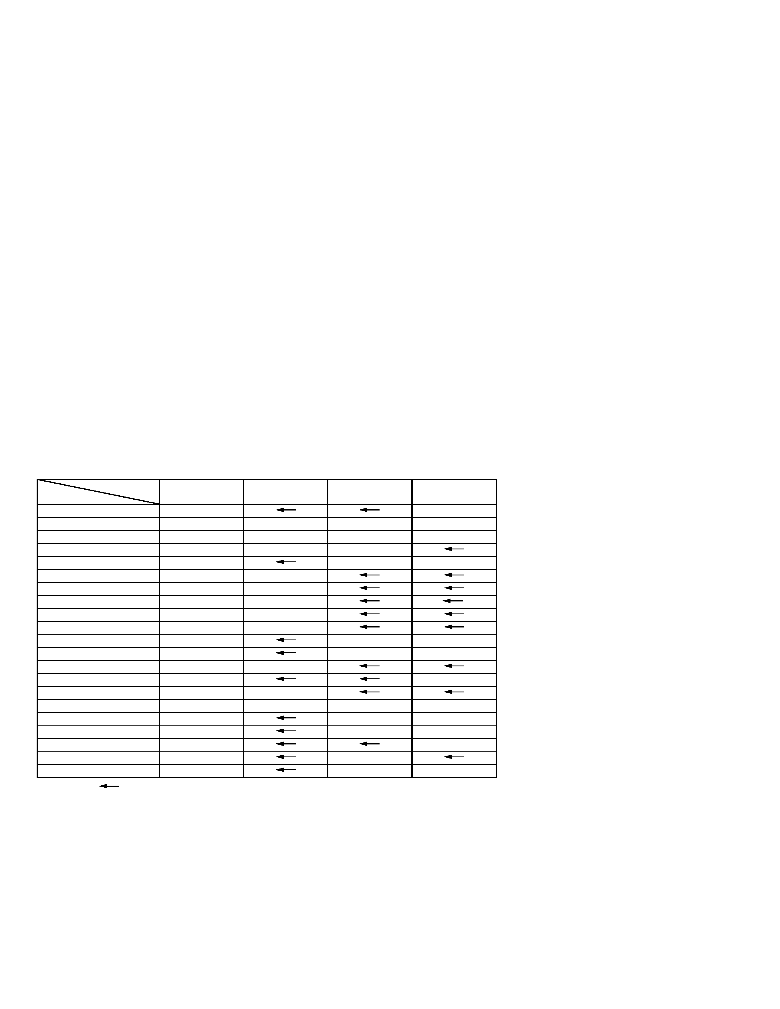
DIFFERENT LIST
DIFFERENT TABLE OF FEATURE
Notes: Mark
is same as left.
1
MODEL
HR-S8960EX
ITEM
POWER PLUG
CEE(CLASSII)
BS(CLASSII)
JOG/SHUTTLE DIAL ON DECK ADV. JOG with SPUTTERING ADVANCED JOG ADV. JOG with SPUTTERING ADVANCED JOG
WINDOW COLOR
HS&SMOKE GRAY PAINT&SMOKE GRAY HS&SMOKE GRAY PAINT&SMOKE GRAY
SATELLITTE CONTROLLER
PROVIDED
OPTIONAL
PROVIDED
SCART CABLE
OPTIONAL
PROVIDED
OPTIONAL
FLYING ERASE HEAD
USED
NOT USED
RE-TAKE
USED
NOT USED
ASSEMBLE EDIT
Z.F.E.
A.F.E.
.
INSERT
USED
NOT USED
AUDIO DUBBING
USED
NOT USED
VIDEO SYSTEM : MESECAM USED(MANUAL)
USED(PLAYBACK)
NOT USED
VIDEO SYSTEM : SECAM
NOT USED
USED
NOT USED
FRONT IN TERMINAL
GOLD
SILVER
L-2 INPUT DECODER
USED
NOT USED
REMOTE PAUSE TERMINAL
USED
NOT USED
BROADCASTING STANDARD
B/G,D/K
B/G,D/K
L,L',B/G
I
STEREO DECODER
NICAM/A2
NICAM(L,B/G)/A2(B/G)
NICAM
RF OUT
USED
NOT USED
USED
VCR PLUS+
SHOWVIEW DELUXE
VIDEOPLUS+ DELUXE
VPS
USED
NOT USED
OSD LANGUAGE
13 LANGUAGES
FRENCH
ENGLISH
HR-S7965EF
HR-S7960EX
HR-S7965EK
3-1
SECTION 3
ADJUSTMENT
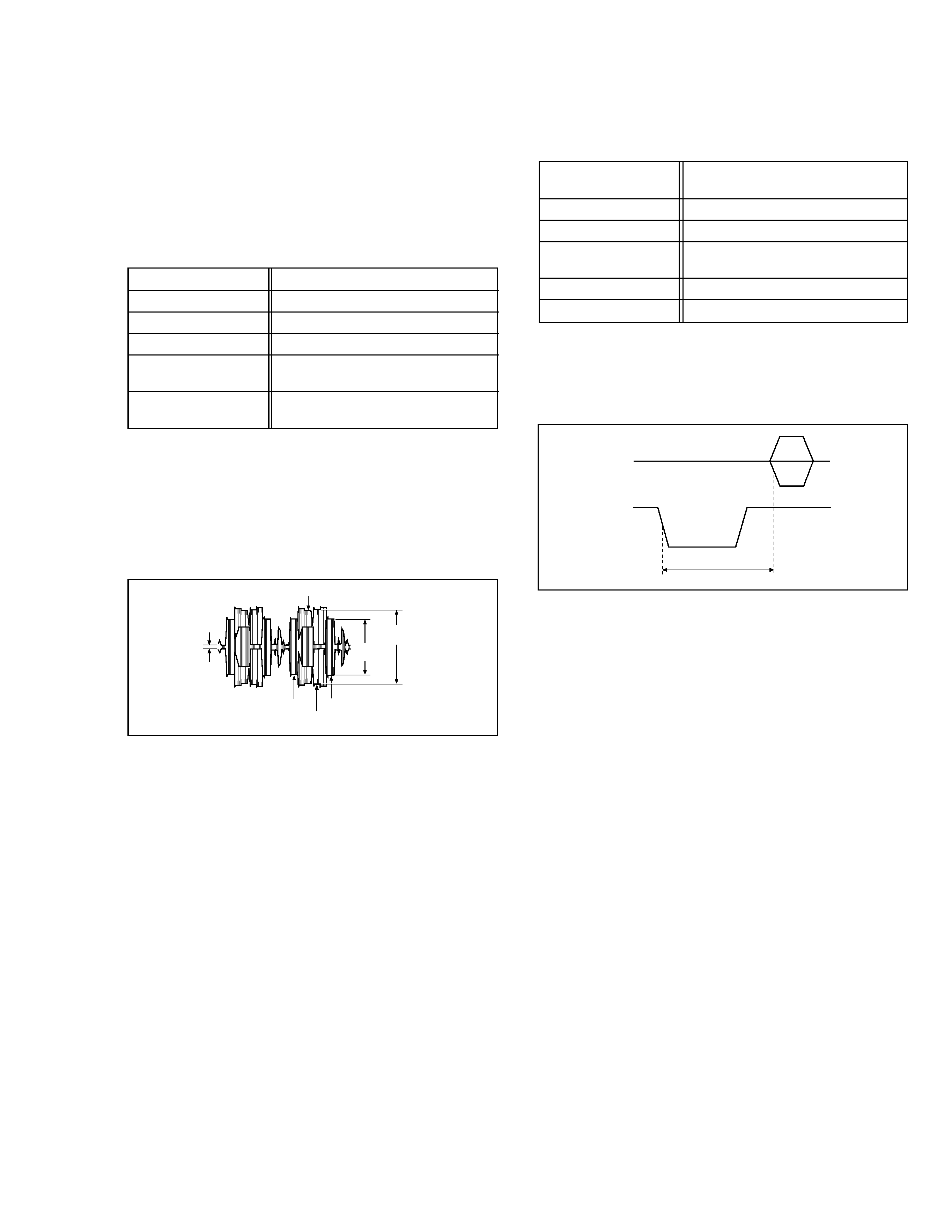
Fig. 3-1-1-2a
SECAM burst position
3.1.1.2 SECAM burst position
(1) Observe the waveforms appeared at the measuring
points (D1) and (D2).
(2) Adjust the adjustment part (F) so that the waveforms tim-
ing width between the H-SYNC and the colour burst sig-
nal becomes the specified value (G).
Signal
(A1)
· Ext. input
(A2)
· Color (colour) bar signal [SECAM]
Mode
(B)
· EE
Equipment
(C)
· Oscilloscope
Measuring point (D1)
· CN1601 Pin 7
(D2)
· CN1601 Pin 3
Adjustment part
(F)
· VR1603
Specified value
(G)
· Tr = 5.6 ± 0.1 µsec
Colour burst signal
H-SYNC
C
(Converted colour)
Y
Specified value (G)
H.rate
3.1.1.1 Colour difference level
(1) Observe the C (converted colour) waveform at the meas-
uring point (D).
(2) Adjust the adjustment part (F1) so that the higher level
of the Yellow and Blue of the C waveform becomes the
specified value (G1).
(3) Adjust the adjustment part (F2) so that the higher level
of the Green and Magenta of the C waveform becomes
the specified value (G2).
Signal
(A1)
· Color (colour) bar signal [SECAM]
Mode
(B)
· EE
Equipment
(C)
· Oscilloscope
Measuring point (D)
· CN1601 Pin 7
Adjustment part
(F1)
· VR1602 (B-Y ADJ)
(F2)
· VR1601 (R-Y ADJ)
Specified value
(G1)
· 460 ± 20 mVp-p (B-Y)
(G2)
· 620 ± 20 mVp-p (R-Y)
3.1.1
PAL/SECAM converter circuit [EF MODEL]
Note:
· Unless otherwise specified in this P/S Converter cir-
cuit adjustments, all measuring points and adjustment
parts are located on the S-P Converter board.
Fig. 3-1-1-1a
Colour difference level
GREEN
YELLOW
BLUE
MAGENTA
H.rate
Specified
value (G2)
Specified
value (G1)
3.1
Electrical adjustment

VICTOR COMPANY OF JAPAN, LIMITED
12,3-chome,Moriya-cho,Kanagawa-ku,Yokohama,Kanagawa-prefecture,221-8528,Japan
AV & MULTIMEDIA COMPANY.
Printed in Japan
0307 VP