SERVICE MANUAL
VIDEO CASSETTE RECORDER
No. 82890
July 2001
This service manual is printed on 100% recycled paper.
COPYRIGHT © 2001 VICTOR COMPANY OF JAPAN, LTD.
HR-S6856EK/S6857EK
Regarding service information other than these sections, refer to the HR-S6855EK service manual (No. 82856).
Also, be sure to note important safety precautions provided in the service manual.
SPECIFICATIONS (The specifications shown pertain specifically to the model HR-S6855EK/S6856EK/S6857EK)
625
TV PR +
TV PR
T
V
TV
+
TV
0000
STOP
FIN
MEN
U
OK
TV/VCR
DAILY/QTDN.
VPS/PDC
AUX
?
WEEKLY/HEBDO
PROG
30 SEC
:
AUDIO
1. , /
ABC
JKL
GHI
MNO
PQRS
TUV
]
WXYZ
DEF
2
3
4
6
5
7
8
9
0
DATE
START
DEBUT
PR
2
4
1
3
ENTER/ENTR
EE
EXPRESS
PUSHOPEN
POUSSER
REVIEW
SP
VCR
VPS/PDC
VPS/PDC
GENERAL
Power requirement
: AC 220 V 240 V `, 50 Hz/60 Hz
Power consumption
: on : 22 W,
off : 3.8 W
Operating Temperature
: 5°C to 40°C
Storage Temperature
: 20°C to 60°C
Operating position
: Horizontal only
Dimensions (WxHxD)
: 400 mm x 94 mm x 278 mm
Weight
: 3.6 kg
Format
: S-VHS/VHS PAL standard
Maximum recording time :
(SP)
: 240 min. with E-240 video cassette
(LP)
: 480 min. with E-240 video cassette
(EP)
: 720 min. with E-240 video cassette
VIDEO/AUDIO
Signal system
: PAL-type colour signal and CCIR monochrome
signal, 625 lines/50 fields
Recording system
: DA4 (Double Azimuth) helical scan system
Signal-to-noise ratio
: 45 dB
Horizontal resolution
:
(SP/LP)
: 250 lines (VHS)
400 lines (S-VHS)
(EP)
: 220 lines (VHS)
350 lines (S-VHS)
Frequency range
: 70 Hz to 10,000 Hz (Normal audio)
20 Hz to 20,000 Hz (Hi-Fi audio)
Input/Output
: 21-pin SCART connectors
(IN/OUT x 1, IN/DECODER x 1)
RCA connectors
(VIDEO IN x 1, AUDIO IN x 1, AUDIO OUT x 1)
S-Video connectors (IN x 1)
TUNER/TIMER
TV channel storage capacity : 99 positions (+AUX position)
Tuning system
: Frequency synthesized tuner
Channel coverage
: VHF 44.5 MHz 143 MHz/
143 MHz 470 MHz/
UHF 470 MHz 862 MHz
Aerial output
: UHF channels 22 69 (Adjustable)
Memory backup time
: Approx. 10 min.
ACCESSORIES
Provided accessories
: RF cable, Satellite Controller, Infrared
remote control unit,
`AA' battery x 2
Specifications shown are for SP mode unless otherwise specified.
E.& O.E. Design and specifications subject to change without notice.
Printed in Japan
VICTOR COMPANY OF JAPAN, LIMITED
VIDEO DIVISION
S40894
MODEL
HR-S6855EK
HR-S6856EK
HR-S6857EK
ITEM
The following table indicate main different points between models HR-S6855EK, HR-S6856EK and HR-S6857EK.
REF.
MODEL
HR-S6855EK
HR-S6856EK
HR-S6857EK
!
NO.
ITEM
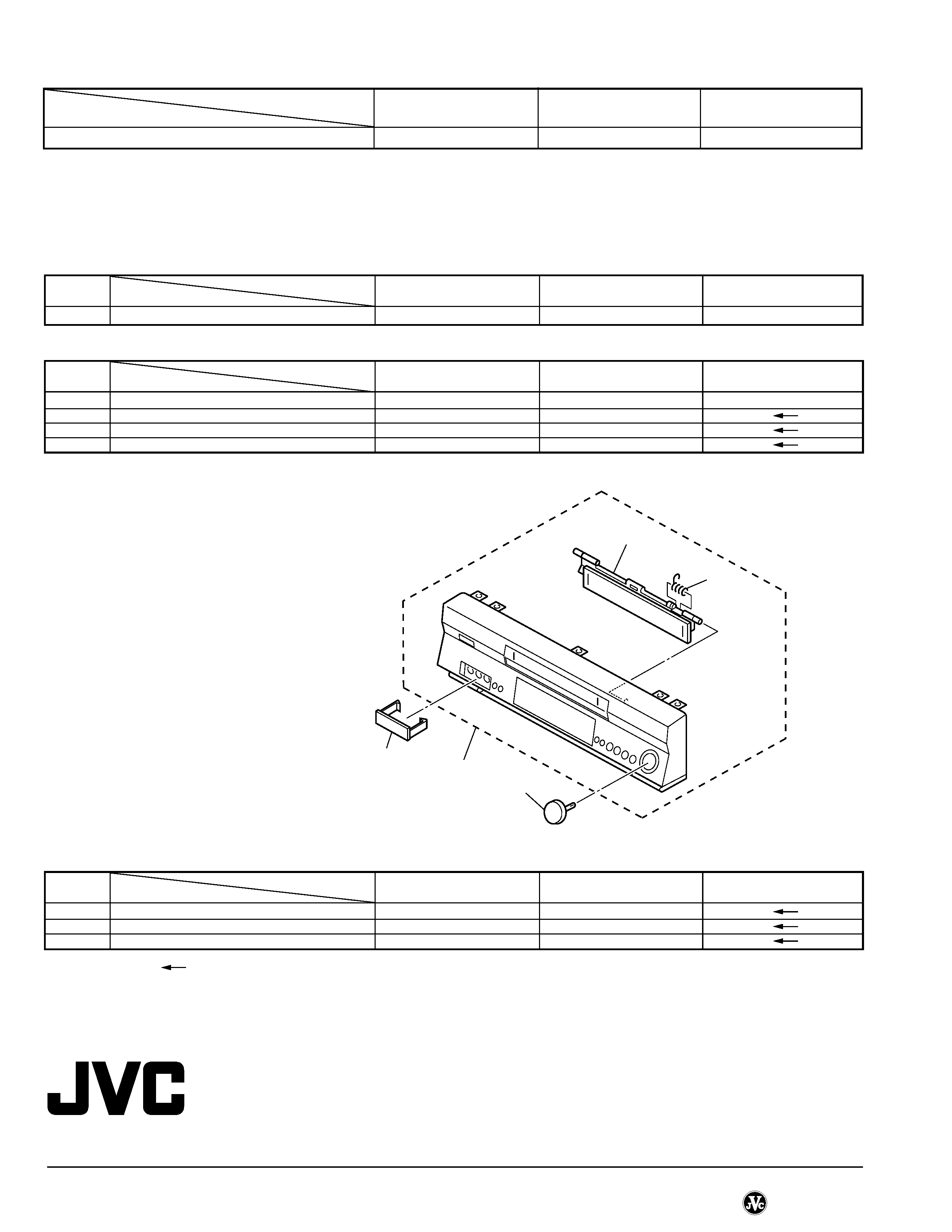
PACKING AND ACCESSORY ASSEMBLY <M1>
The following tables indicate different parts number between models HR-S6855EK, HR-S6856EK and HR-S6857EK.
Notes : Mark
is same as left.
Mark -- is not used.
Mark * reference model was also changed.
FRONT PANEL window color
CLEAR
GREEN
BLUE
315
CAP(JACK)
LP30809-001B
*--
*--
! 501
FRONT PANEL ASSY
LP10333-017E
LP10333-051D
LP10333-052D
501A
CASSETTE DOOR
LP20961-007B
*LP20961-007C
*
529
KNOB ASSY
LP31019-001C
*LP31019-001D
*
535
CAP(JACK)
--
*LP30809-001C
*
REF.
MODEL
HR-S6855EK
HR-S6856EK
HR-S6857EK
!
NO.
ITEM
FINAL ASSEMBLY <M2>
PW1
MAIN BOARD ASSY
LPA10140-01B
*LPA10140-01C
*
IC3001
IC(MCU)
HD6432194SBD11F
*HD6432194SBD04F
*
B8
MG RESISTOR
--
*NRSA02J-0R0X
*
REF.
MODEL
HR-S6855EK
HR-S6856EK
HR-S6857EK
!
NO.
ITEM
MAIN BOARD ASSEMBLY <03>
BEWARE OF BOGUS PARTS
Parts that do not meet specifications may
cause trouble in regard to safety and per-
formance. We recommend that genuine JVC
parts be used.
501A
501B
529
501
535
E. & O. E. No. 82890
(Sanwa)-V14S11/S12
SERVICE MANUAL
No. 82856
May 2001
HR-S6850EU,S6851EU,S6852EU,S6855EK
SPECIFICATIONS (The specifications shown pertain specifically to the model HR-S6850EU/S6851EU/6852EU)
VIDEO CASSETTE RECORDER
Printed in Japan
This service manual is printed on 100% recycled paper.
COPYRIGHT © 2001 VICTOR COMPANY OF JAPAN, LTD.
HR-S6850EU,S6851EU,S5852EU,S6855EK
No.
82856
VICTOR COMPANY OF JAPAN, LIMITED
VIDEO DIVISION
S40894
GENERAL
Power requirement
: AC 220 V 240 V ` , 50 Hz/60 Hz
Power consumption
Power on
: 22 W
Power off
3.8 W
Temperature
Operating
: 5°C to 40°C
Storage
: 20°C to 60°C
Operating position
: Horizontal only
Dimensions (WxHxD)
: 400 mm x 94 mm x 278 mm
Weight
: 3.6 kg
Format
: S-VHS/VHS PAL standard
Maximum recording time
(SP)
: 240 min. with E-240 video cassette
(LP)
: 480 min. with E-240 video cassette
(EP)
: 720 min. with E-240 video cassette
VIDEO/AUDIO
Signal system
: PAL-type colour signal and CCIR
monochrome signal, 625 lines 50 fields
Recording system
: DA4 (Double Azimuth) head helical scan system
Signal-to-noise ratio
: 45 dB
Horizontal resolution
(SP/LP)
: 250 lines (VHS)
400 lines (S-VHS)
(EP)
: 220 lines (VHS)
350 lines (S-VHS)
Frequency range
: 70 Hz to 10,000 Hz (Normal audio)
20 Hz to 20,000 Hz (Hi-Fi audio)
Input/Output
: 21-pin SCART connectors:
IN/OUT x 1, IN/DECODER x 1
RCA connectors:
VIDEO IN x 1, AUDIO IN x 1, AUDIO OUT x 1
S-Video connector: IN x 1
TUNER/TIMER
TV channel storage capacity
: 99 positions (+AUX position)
Tuning system
: Frequency synthesized tuner
Channel coverage
: VHF 47 MHz 89 MHz/
104 MHz 300 MHz/
302 MHz 470 MHz
UHF 470 MHz 862 MHz
Aerial output
: UHF channels 22 69 (Adjustable)
Memory backup time
: Approx. 10 min.
ACCESSORIES
Provided accessories
: RF cable,
Infrared remote control unit,
"R6" battery x 2
Specifications shown are for SP mode unless otherwise specified.
E.& O.E. Design and specifications subject to change without
notice.

3. ELECTRICAL ADJUSTMENT
3.1 Precaution ............................................................................ 3-1
3.1.1 Required test equipments ............................................... 3-1
3.1.2 Required adjustment tools ............................................... 3-1
3.1.3 Color (colour) bar signal,Color (colour) bar pattern ......... 3-1
3.1.4 Switch settings and standard precautions ....................... 3-1
3.1.5 EVR Adjustment .............................................................. 3-1
3.2 Servo circuit .......................................................................... 3-2
3.2.1 Switching point ................................................................ 3-2
3.2.2 Slow tracking preset ........................................................ 3-2
3.3 Video circuit .......................................................................... 3-2
3.3.1 D/A level .......................................................................... 3-2
3.3.2 EE Y/PB Y (S-VHS/VHS) level ......................................... 3-2
3.3.3 REC color (colour) level ................................................... 3-3
3.3.4 Video EQ (Frequency response) ..................................... 3-3
3.3.5 Auto picture initial setting ................................................. 3-4
3.4 Audio circuit ............................................................................ 3-4
3.4.1 Audio REC FM ................................................................. 3-4
3.5 Syscon circuit ......................................................................... 3-4
3.5.1 Timer clock ...................................................................... 3-4
4. CHARTS AND DIAGRAMS
NOTES OF SCHEMATIC DIAGRAM .......................................... 4-1
CIRCUIT BOARD NOTES ........................................................... 4-2
4.1 BOARD INTERCONNECTIONS .......................................... 4-3
4.2 MAIN (VIDEO/AUDIO) SCHEMATIC DIAGRAM .................. 4-5
4.3 MAIN (ON SCREEN) SCHEMATIC DIAGRAM .................... 4-7
4.4 MAIN (SYSCON) SCHEMATIC DIAGRAM .......................... 4-9
4.5 MAIN (SW.REG) SCHEMATIC DIAGRAM ......................... 4-11
4.6 MAIN (TUNER) SCHEMATIC DIAGRAM ........................... 4-13
4.7 MAIN (SW/DISPLAY), S-JACK AND ADV.JOG
SCHEMATIC DIAGRAMS ................................................... 4-15
4.8 MAIN (MAIN TERMINAL) SCHEMATIC DIAGRAM ............ 4-17
4.9 2D DIGITAL SCHEMATIC DIAGRAM ................................. 4-19
4.10 TERMINAL (S-SUB) SCHEMATIC DIAGRAM ................. 4-21
4.11 TERMINAL (I/O) SCHEMATIC DIAGRAM ....................... 4-23
4.12 DEMODULATOR SCHEMATIC DIAGRAM ...................... 4-25
4.13 2D DIGITAL AND DEMODULATOR CIRCUIT BOARDS . 4-27
4.14 TERMINAL CIRCUIT BOARD ......................................... 4-28
4.15 MAIN CIRCUIT BOARD ................................................... 4-29
4.16 REMOTE CONTROLLER SCHEMATIC DIAGRAM ......... 4-32
4.17 FDP GRID ASSIGNMENT AND ANODE CONNECTION 4-33
4.18 WAVEFORMS .................................................................. 4-34
4.19 VOLTAGE CHARTS ......................................................... 4-36
4.20 CPU PIN FUNCTION ....................................................... 4-37
4.21 SYSTEM CONTROL BLOCK DIAGRAM ......................... 4-39
4.22 VIDEO BLOCK DIAGRAM ............................................... 4-41
4.23 AUDIO BLOCK DIAGRAM ............................................... 4-45
5. PARTS LIST
5.1 PACKING AND ACCESSORY ASSEMBLY <M1> ............... 5-1
5.2 FINAL ASSEMBLY <M2> .................................................... 5-2
5.3 MECHANISM ASSEMBLY <M4> ........................................ 5-4
5.4 ELECTRICAL PARTS LIST .................................................. 5-6
MAIN BOARD ASSEMBLY <03> ............................................... 5-6
2D DIGITAL BOARD ASSEMBLY <05> ................................... 5-13
TERMINAL BOARD ASSEMBLY <06> ................................... 5-14
A/C HEAD BOARD ASSEMBLY <12> ..................................... 5-16
DEMOD BOARD ASSEMBLY <14> ........................................ 5-16
S.JACK BOARD ASSEMBLY <36> ......................................... 5-16
ADV.JOG BOARD ASSEMBLY <38> ....................................... 5-16
LOADING MOTOR BOARD ASSEMBLY <55> ....................... 5-16
Important Safety Precautions
INSTRUCTIONS
1. DISASSEMBLY
1.1 Disassembly flow chart ......................................................... 1-1
1.2 How to read the disassembly and assembly ........................ 1-1
1.3 Disassembly/assembly method ............................................ 1-1
1.4 Service position .................................................................... 1-4
1.4.1 How to set the "Service position" ..................................... 1-4
1.5 Mechanism service mode ..................................................... 1-4
1.5.1 How to set the "Mechanism service mode" ..................... 1-4
1.6 Jig RCU mode ....................................................................... 1-4
1.6.1 Setting the Jig RCU mode ............................................... 1-4
1.6.2 Setting the User RCU mode ............................................ 1-4
1.7 Servicing items related to video navigation .......................... 1-4
1.8 Emergency display function .................................................. 1-5
1.8.1 Displaying the EMG information ...................................... 1-5
1.8.2 Clearing the EMG history ................................................ 1-5
1.8.3 EMG content description ................................................. 1-6
1.8.4 EMG detail information <1> ............................................. 1-7
1.8.5 EMG detail information <2> ............................................. 1-8
2. MECHANISM ADJUSTMENT
2.1 Before starting repair and adjustment ................................... 2-1
2.1.1 Precautions ..................................................................... 2-1
2.1.2 Checking for proper mechanical operations .................... 2-1
2.1.3 Manually removing the cassette tape .............................. 2-1
2.1.4 Jigs and tools required for adjustment ............................. 2-2
2.1.5 Maintenance and inspection ............................................ 2-3
2.2 Replacement of major parts ................................................. 2-6
2.2.1 Before starting disassembling (Phase matching between
mechanical parts) ............................................................ 2-6
2.2.2 How to set the "Mechanism assembling mode" ............... 2-6
2.2.3 Cassette holder assembly ............................................... 2-6
2.2.4 Pinch roller arm assembly ............................................... 2-8
2.2.5 Guide arm assembly and press lever assembly .............. 2-8
2.2.6 A/C head ......................................................................... 2-8
2.2.7 Loading motor ................................................................. 2-8
2.2.8 Capstan motor ................................................................. 2-9
2.2.9 Pole base assembly (supply or take-up side) .................. 2-9
2.2.10 Rotary encoder ........................................................... 2-10
2.2.11 Clutch unit ................................................................... 2-10
2.2.12 Change lever assembly, direct gear, clutch gear and
coupling gear .............................................................. 2-10
2.2.13 Link lever ..................................................................... 2-11
2.2.14 Cassette gear, control cam and worm gear ................ 2-11
2.2.15 Control plate ............................................................... 2-11
2.2.16 Loading arm gear (supply or take-up side) and
loading arm gear shaft ................................................ 2-12
2.2.17 Take-up lever, take-up head and control plate guide .. 2-13
2.2.18 Capstan brake assembly ............................................ 2-13
2.2.19 Sub brake assembly (take-up side) ............................ 2-13
2.2.20 Main brake assembly (take-up side), reel disk (take-up side)
and main brake assembly (supply side) ................................. 2-13
2.2.21 Tension brake assembly, reel disk (supply side) and
tension arm assembly ................................................. 2-14
2.2.22 Idler lever, idler arm assembly .................................... 2-14
2.2.23 Stator assembly .......................................................... 2-14
2.2.24 Rotor assembly ........................................................... 2-14
2.2.25 Upper drum assembly ................................................. 2-15
2.3 Compatibility adjustment .................................................... 2-16
2.3.1 FM waveform linearity ................................................... 2-16
2.3.2 Height and tilt of the A/C head ...................................... 2-17
2.3.3 A/C head phase (X-value) ............................................. 2-17
2.3.4 Standard tracking preset ............................................... 2-18
2.3.5 Tension pole position ..................................................... 2-18
TABLE OF CONTENTS
Section
Title
Page
Section
Title
Page
HR-S6850EU
HR-S6851EU
HR-S6852EU
HR-S6855EK
VIDEO SYSTEM
PAL/MESECAM(MANUAL) PAL/MESECAM(MANUAL)
PAL/MESECAM(MANUAL)
PAL/NTSC ON PAL TV
/NTSC ON PAL TV
/NTSC ON PAL TV
/NTSC ON PAL TV
BROADCASTING STANDARD
B/G,D/K
B/G,D/K
B/G,D/K
I
STEREO DECODER
NICAM/A2
NICAM/A2
NICAM/A2
NICAM
RF OUT SYSTEM [INITIAL]
G,K
G,K
G,K
I
VCR PLUS+
SHOWVIEW DELUXE
SHOWVIEW DELUXE
SHOWVIEW DELUXE
VIDEOPLUS+ DELUXE
VPS(AUTO)
USED
USED
USED
NOT USED
INITIAL (TIMER)
GER,AUS,SWISS:ON,
GER,AUS,SWISS:ON,
GER,AUS,SWISS:ON,
OFF
OTHER:OFF
OTHER:OFF
OTHER:OFF
CABLE BOX OR DBS. BOX OR SAT CTL
READY
READY
READY
USED
LANGUAGE [INITIAL]
13 LANG. [E]
13 LANG. [E]
13 LANG. [E]
ENG
(ON SCREEN DISPLAY)
GOST
USED
NOT USED
NOT USED
NOT USED
FRONT PANEL COLOR
PURE SILVER
PURE SILVER
BLACK
PURE SILVER
WINDOW COLOR
SMOKE LIGHT GRAY
GREEN
SMOKE PINK
CLEAR
CABLE MOUSE
OPTION
OPTION
OPTION
PROVIDED
The following table lists the differing points between Models ( HR-S6850EU, HR-S6851EU, HR-S6852EU and HR-S6855EK) in this series.
Important Safety Precautions
Prior to shipment from the factory, JVC products are strictly inspected to conform with the recognized product safety and electrical codes of the
countries in which they are to be sold. However, in order to maintain such compliance, it is equally important to implement the following precautions
when a set is being serviced.
Fig.1
1. Locations requiring special caution are denoted by labels and in-
scriptions on the cabinet, chassis and certain parts of the product.
When performing service, be sure to read and comply with these
and other cautionary notices appearing in the operation and serv-
ice manuals.
2. Parts identified by the
! symbol and shaded (
) parts are
critical for safety.
Replace only with specified part numbers.
Note: Parts in this category also include those specified to com-
ply with X-ray emission standards for products using
cathode ray tubes and those specified for compliance
with various regulations regarding spurious radiation
emission.
3. Fuse replacement caution notice.
Caution for continued protection against fire hazard.
Replace only with same type and rated fuse(s) as specified.
4. Use specified internal wiring. Note especially:
1) Wires covered with PVC tubing
2) Double insulated wires
3) High voltage leads
5. Use specified insulating materials for hazardous live parts. Note
especially:
1) Insulation Tape
3) Spacers
5) Barrier
2) PVC tubing
4) Insulation sheets for transistors
6. When replacing AC primary side components (transformers, power
cords, noise blocking capacitors, etc.) wrap ends of wires securely
about the terminals before soldering.
Power cord
Fig.2
10. Also check areas surrounding repaired locations.
11. Products using cathode ray tubes (CRTs)
In regard to such products, the cathode ray tubes themselves, the
high voltage circuits, and related circuits are specified for compli-
ance with recognized codes pertaining to X-ray emission.
Consequently, when servicing these products, replace the cath-
ode ray tubes and other parts with only the specified parts. Under
no circumstances attempt to modify these circuits.
Unauthorized modification can increase the high voltage value and
cause X-ray emission from the cathode ray tube.
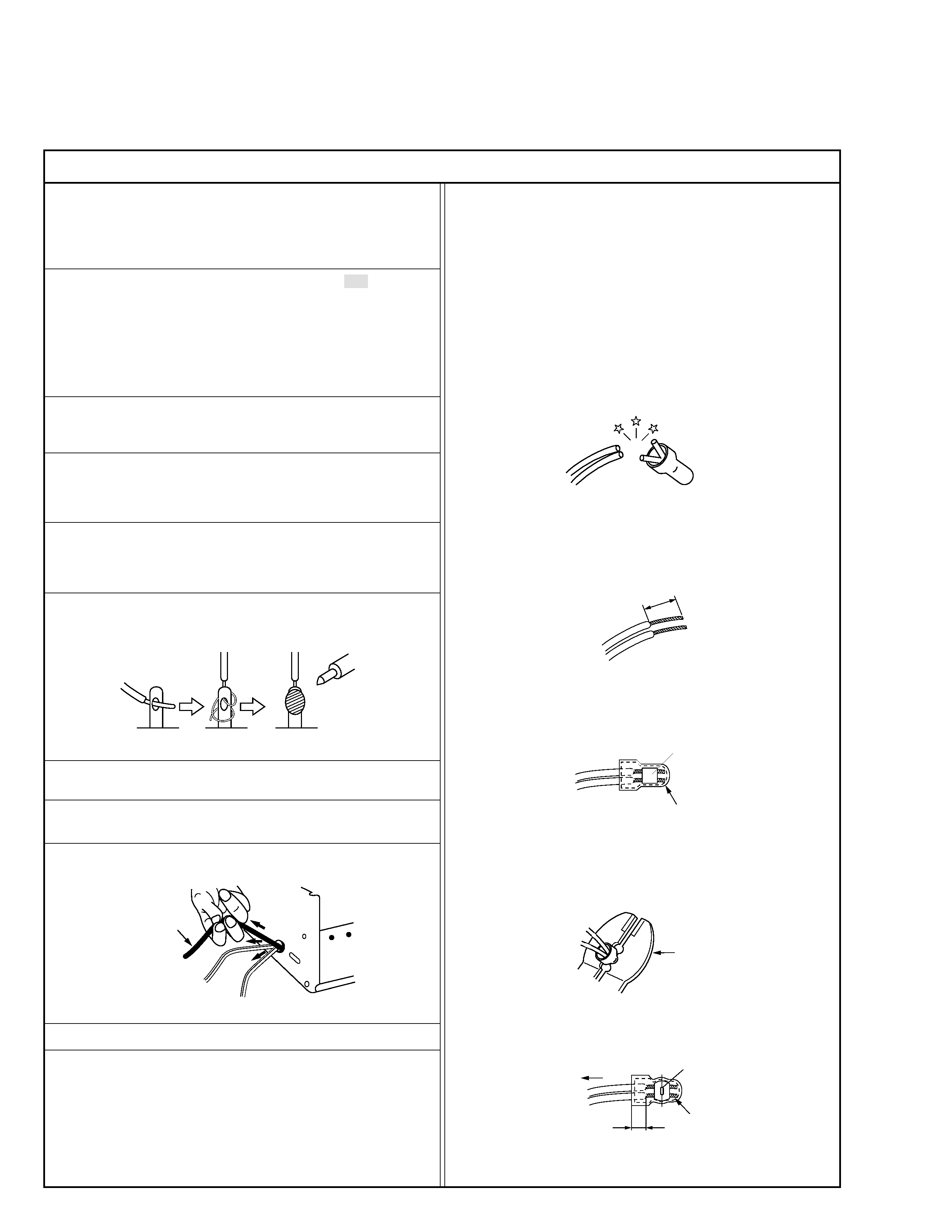
12. Crimp type wire connector
In such cases as when replacing the power transformer in sets
where the connections between the power cord and power trans-
former primary lead wires are performed using crimp type connec-
tors, if replacing the connectors is unavoidable, in order to prevent
safety hazards, perform carefully and precisely according to the
following steps.
1) Connector part number : E03830-001
2) Required tool : Connector crimping tool of the proper type which
will not damage insulated parts.
3) Replacement procedure
(1) Remove the old connector by cutting the wires at a point
close to the connector.
Important : Do not reuse a connector (discard it).
Fig.7
cut close to connector
Fig.3
(2) Strip about 15 mm of the insulation from the ends of the
wires. If the wires are stranded, twist the strands to avoid
frayed conductors.
15 mm
Fig.4
(3) Align the lengths of the wires to be connected. Insert the
wires fully into the connector.
Connector
Metal sleeve
Fig.5
(4) As shown in Fig.6, use the crimping tool to crimp the metal
sleeve at the center position. Be sure to crimp fully to the
complete closure of the tool.
I
·Precautions during Servicing
7. Observe that wires do not contact heat producing parts (heatsinks,
oxide metal film resistors, fusible resistors, etc.)
8. Check that replaced wires do not contact sharp edged or pointed
parts.
9. When a power cord has been replaced, check that 10-15 kg of
force in any direction will not loosen it.
1.2
5
2.0
5.5
Crimping tool
Fig.6
(5) Check the four points noted in Fig.7.
Not easily pulled free
Crimped at approx. center
of metal sleeve
Conductors extended
Wire insulation recessed
more than 4 mm
S40888-01